Table of Contents
Advertisement
Quick Links
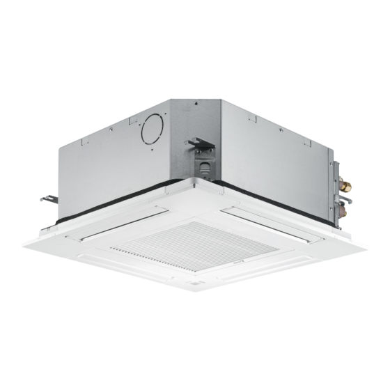
SPLIT-TYPE, HEAT PUMP AIR CONDITIONERS
TECHNICAL & SERVICE MANUAL
Indoor unit
[Model Name]
SLZ-M15FA.TH
SLZ-M15FA
SLZ-M15FA.TH-ER
SLZ-M25FA.TH
SLZ-M25FA
SLZ-M25FA.TH-ER
SLZ-M35FA.TH
SLZ-M35FA
SLZ-M35FA.TH-ER
SLZ-M50FA.TH
SLZ-M50FA
SLZ-M50FA.TH-ER
SLZ-M60FA.TH
SLZ-M60FA
SLZ-M60FA.TH-ER
Model name
indication
INDOOR UNIT
[Service Ref.]
R32/R410A
Note:
• This manual describes service
data of the indoor units only.
CONTENTS
1. REFERENCE MANUAL ...................... 2
2. SAFETY PRECATION ......................... 3
3. PARTS NAMES AND FUNCTIONS ..... 9
4. SPECIFICATIONS ............................. 14
5. NOISE CRITERION CURVES ........... 14
6. OUTLINES AND DIMENSIONS ......... 16
7. WIRING DIAGRAM ............................ 18
8. REFRIGERANT SYSTEM DIAGRAM ..... 19
9. TROUBLESHOOTING ....................... 20
10. 4-WAY AIR FLOW SYSTEM .............. 33
11. DISASSEMBLY PROCEDURE .......... 35
PARTS CATALOG (OCB522)
February 2018
No. OCH522
Advertisement
Table of Contents

Related Manuals for Mitsubishi Electric MR. SLIM SLZ Series


Summary of Contents for Mitsubishi Electric MR. SLIM SLZ Series
-
Page 1: Table Of Contents
SPLIT-TYPE, HEAT PUMP AIR CONDITIONERS February 2018 No. OCH522 TECHNICAL & SERVICE MANUAL R32/R410A Indoor unit Note: [Model Name] [Service Ref.] • This manual describes service SLZ-M15FA.TH data of the indoor units only. SLZ-M15FA SLZ-M15FA.TH-ER SLZ-M25FA.TH SLZ-M25FA SLZ-M25FA.TH-ER SLZ-M35FA.TH SLZ-M35FA SLZ-M35FA.TH-ER SLZ-M50FA.TH SLZ-M50FA... -
Page 2: Reference Manual
REFERENCE MANUAL OUTDOOR UNIT’S SERVICE MANUAL Service Ref. Service Manual No. MXZ-2D33VA OBH626 MXZ-2D42VA2 OBB626 MXZ-2D53VA(H)2 MXZ-2E53VAHZ MXZ-3E54VA MXZ-3E68VA OBH723 MXZ-4E72VA OBB723 MXZ-4E83VAHZ MXZ-4E83VA MXZ-5E102VA MXZ-6D122VA2 MXZ-2F33VF* MXZ-2F42VF* OBH626 MXZ-2F53VF(H)* OBH790 MXZ-3F54VF* MXZ-3F68VF* MXZ-4F72VF* SUZ-KA25VA6 SUZ-KA35VA6 TCB004 SUZ-KA50VA6 TCH004 SUZ-KA60VA6 OCH527 PUHZ-ZRP71VHA OCB527... -
Page 3: Safety Precation
SAFETY PRECAUTION MEANINGS OF SYMBOLS DISPLAYED ON THE UNIT This mark is for R32 refrigerant only. Refrigerant type is written on nameplate of outdoor unit. WARNING Read the OPERATION MANUAL carefully before operation. Service personnel are required to carefully read the OPERATION MANUAL and INSTALLATION MANUAL before operation. Further information is available in the OPERATION MANUAL, INSTALLATION MANUAL, and the like. - Page 4 [1] Warning for service (1) Do not alter the unit. (2) For installation and relocation work, follow the instructions in the Installation Manual and use tools and pipe components specifically made for use with refrigerant specified in the outdoor unit installation manual. (3) Ask a dealer or an authorized technician to install, relocate and repair the unit.
- Page 5 [4] Cautions for unit using R32 refrigerant Basic work procedures are the same as those for conventional units using refrigerant R410A. However, pay careful attention to the following points. (1) Information on servicing (1-1) Checks on the Area Prior to beginning work on systems containing flammable refrigerants, safety checks are necessary to ensure that the risk of ignition is minimized.
- Page 6 (3) Repair to intrinsically Safe Components Do not apply any permanent inductive or capacitance loads to the circuit without ensuring that this will not exceed the permissible voltage and current permitted for the equipment in use. Intrinsically safe components are the only types that can be worked on while live in the presence of a flammable atmos- phere.
- Page 7 a) Become familiar with the equipment and its operation. b) Isolate system electrically. c) Before attempting the procedure, ensure that: • mechanical handling equipment is available, if required, for handling refrigerant cylinders; • all personal protective equipment is available and being used correctly; •...
- Page 8 Unit Electronic weighing scale [5] Service tools Use the below service tools as exclusive tools for R32/R410A refrigerant. Refer to the spec name plate on outdoor unit for the type of refrigerant being used. Tool name Specifications Gauge manifold · Use the existing fitting specifications . (UNF1/2) ·...
-
Page 9: Parts Names And Functions
PARTS NAMES AND FUNCTIONS 3-1. INDOOR UNIT Filter Removes dust and pollutants Horizontal Air Outlet from drawn in air. Sets horizontal airflow automatically during cooling or dehumidifying. Grille Auto Air Swing Vane Disperses airflow up and down and adjusts the angle of airflow direction. - Page 10 3-2. WIRELESS REMOTE CONTROLLER Transmission area Not available Remote controller display Battery replacement indicator Set Temperature buttons OFF/ON button Mode button (Changes operation mode) Fan Speed button (Changes fan speed) Airflow button (Changes up/down airflow direction) i-see button Timer ON button Menu button Timer OFF button SET/SEND button...
- Page 11 3-3. Wired remote controller (Option) PAR-33MAA The functions which can be used are restricted according to each model. The main display can be displayed in 2 different modes: "Full" and "Basic." Display The initial setting is "Full." 1 Operation mode Appears when the On/Off timer or Night setback Indoor unit operation mode appears here.
- Page 12 Menu structure Press the button. MENU Main menu Move the cursor to the desired item with the buttons, and press the button. SELECT Vane · Louver · Vent. (Lossnay) High power Timer ON/OFF timer Auto-OFF timer Weekly timer Restriction Temp. range Operation lock Energy saving Auto return...
- Page 13 Main menu list Setting and display items Setting details Vane · Louver · Vent. Use to set the vane angle. • Select a desired vane setting from 5 different settings. (Lossnay) Use to turn ON/OFF the louver. • Select a desired setting from "ON" and "OFF." Use to set the amount of ventilation.
-
Page 14: Specifications
SPECIFICATIONS Indoor unit service ref. SLZ-M15FA.TH SLZ-M25FA.TH SLZ-M35FA.TH SLZ-M50FA.TH SLZ-M60FA.TH SLZ-M15FA.TH-ER SLZ-M25FA.TH-ER SLZ-M35FA.TH-ER SLZ-M50FA.TH-ER SLZ-M60FA.TH-ER Mode Cooling Heating Cooling Heating Cooling Heating Cooling Heating Cooling Heating Power supply (phase, cycle, voltage) Single phase 50 Hz, 230 V Input [kW] 0.02 0.02 0.02 0.02... - Page 15 <50Hz> <50Hz> SLZ-M50FA.TH SLZ-M35FA.TH NOTCH SPL(dB) LINE NOTCH SPL(dB) LINE High SLZ-M50FA.TH-ER High SLZ-M35FA.TH-ER Medium Medium NC-70 NC-70 NC-60 NC-60 NC-50 NC-50 NC-40 NC-40 NC-30 NC-30 APPROXIMATE APPROXIMATE THRESHOLD OF THRESHOLD OF HEARING FOR NC-20 HEARING FOR NC-20 CONTINUOUS CONTINUOUS NOISE NOISE 1000...
-
Page 16: Outlines And Dimensions
OUTLINES AND DIMENSIONS SLZ-M15FA.TH SLZ-M25FA.TH SLZ-M35FA.TH SLZ-M50FA.TH SLZ-M60FA.TH SLZ-M15FA.TH-ER SLZ-M25FA.TH-ER SLZ-M35FA.TH-ER SLZ-M50FA.TH-ER SLZ-M60FA.TH-ER Unit: mm OCH522... - Page 17 WIRED REMOTE CONTROLLER WIRELESS REMOTE CONTROLLER Unit: mm PAR-SL100A-E PAR-33MAA 64.7 OCH522...
-
Page 18: Wiring Diagram
WIRING DIAGRAM SLZ-M15FA.TH SLZ-M25FA.TH SLZ-M35FA.TH SLZ-M50FA.TH SLZ-M60FA.TH SLZ-M15FA.TH-ER SLZ-M25FA.TH-ER SLZ-M35FA.TH-ER SLZ-M50FA.TH-ER SLZ-M60FA.TH-ER OUTDOOR UNIT See fig.1 CN32 CN3C CN01 (WH) (BU) (BK) 1 2 3 4 5 J42 J41 (WH) LED1 OFF ON CN51 CN5Y (WH) (WH) CN41 (WH) CN2L LED2 CN22 (RD) -
Page 19: Refrigerant System Diagram
REFRIGERANT SYSTEM DIAGRAM SLZ-M15FA.TH SLZ-M25FA.TH SLZ-M35FA.TH SLZ-M50FA.TH SLZ-M60FA.TH SLZ-M15FA.TH-ER SLZ-M25FA.TH-ER SLZ-M35FA.TH-ER SLZ-M50FA.TH-ER SLZ-M60FA.TH-ER Strainer Heat exchanger Refrigerant GAS pipe connection (Flare) Condenser/evaporator temperature thermistor (TH5) Refrigerant flow in cooling Refrigerant flow in heating Refrigerant LIQUID pipe connection (Flare) Pipe temperature thermistor/liquid Room temperature (TH2) -
Page 20: Troubleshooting
TROUBLESHOOTING 9-1. TROUBLESHOOTING <Check code displayed by self-diagnosis and actions to be taken for service (summary)> Present and past check codes are logged, and they can be displayed on the wired remote controller or controller board of out- door unit. Actions to be taken for service, which depends on whether or not the trouble is reoccurring in the field, are summa- rized in the table below. - Page 21 Refer to the following tables for details on the check codes. [Output pattern A] Beeper sounds Beep Beep Beep Beep Beep Beep Beep 1 st 2 nd 3 rd n th 1 st 2 nd OPERATION · · · Repeated INDICATOR lamp blinking pattern...
- Page 22 • If the unit cannot be operated properly after the test run, refer to the following table to find out the cause. Symptom Cause Wired remote controller •For about 2 minutes after power-on, operation of the For about 2 minutes after power-on PLEASE WAIT remote controller is not possible due to system startup.
- Page 23 Note: Errors to be detected in outdoor unit, such as codes starting with F, U or E (excluding E0 to E7), are not covered in this document. Please refer to the outdoor unit's service manual 9-3. SELF-DIAGNOSIS ACTION TABLE for the details. Check code Abnormal point and detection method Countermeasure...
- Page 24 Check code Abnormal point and detection method Countermeasure Cause Freezing/overheating protection is (Cooling or drying mode) (Cooling or drying mode) operating 1 Clogged filter (reduced airflow) 1 Check clogging of the filter. Freezing protection (Cooling mode) Short cycle of air path Remove blockage.
- Page 25 Abnormal point and detection method Countermeasure Check code Cause Pipe temperature thermistor/Condenser /Evaporator (TH5) 1 The unit is in 3-minute resume protec- 1 Defective thermistor 1– Check resistance value of thermistor. tion mode if short/open of thermistor is characteristics For characteristics, refer to (P1). detected.
- Page 26 Abnormal point and detection method Countermeasure Check code Cause Remote controller transmission error(E3)/signal receiving error(E5) 1 2 remote controllers are set as 1 Set a remote controller to main, and the 1 Abnormal if remote controller could not other to sub. “main.”...
- Page 27 Check code Abnormal point and detection method Countermeasure Cause Forced compressor stop (due to water leakage abnormality) 1 When the intake temperature subtracted 1 Drain pump trouble 1 Check the drain pump. from liquid pipe temperature is less than −10°C, drain sensor detects whether it is 2 Drain defective 2 Please check whether water can be drained.
- Page 28 9-4. TROUBLESHOOTING OF PROBLEMS Note: Refer to the manual of outdoor unit for the detail of remote controller. Phenomena Cause Countermeasure (1) LED2 on indoor controller board • When LED1 on indoor controller board is also off. 1 Check the voltage of outdoor power 1 Power supply of rated voltage is not supplied to out- is off.
- Page 29 9-5. TEST POINT DIAGRAM 9-5-1. Indoor controller board SLZ-M15FA.TH SLZ-M25FA.TH SLZ-M35FA.TH SLZ-M50FA.TH SLZ-M60FA.TH SLZ-M15FA.TH-ER SLZ-M25FA.TH-ER SLZ-M35FA.TH-ER SLZ-M50FA.TH-ER SLZ-M60FA.TH-ER CN22 CN5Y Connect to the terminal block (TB5) i-See sensor motor (MT) Vane motor (MV) (Remote controller transmission line) 12 V pulse output 12 V pulse output 10.4–14.6 V DC J41, J42...
- Page 30 9-6. FUNCTION OF DIP SWITCH Each function is controlled by the DIP switch and the jumper wire on the indoor controller board. ■ The black square ( ) indicates a switch position. Switch Functions Setting by the DIP switch Remarks Model Setting 1 2 3 4 5...
- Page 31 9-7. TROUBLE CRITERION OF MAIN PARTS SLZ-M15FA.TH SLZ-M25FA.TH SLZ-M35FA.TH SLZ-M50FA.TH SLZ-M60FA.TH SLZ-M15FA.TH-ER SLZ-M25FA.TH-ER SLZ-M35FA.TH-ER SLZ-M50FA.TH-ER SLZ-M60FA.TH-ER Parts name Check method and criterion Room temperature Measure the resistance with a tester. thermistor (TH1) (Parts temperature 10 to 30°C) Pipe temperature Abnormal Normal thermistor/liquid (TH2) Opened or short-circuited...
- Page 32 9-7-1. Thermistor Characteristic Graph < Thermistor for lower temperature > •Room temperature thermistor (TH1) •Pipe temperature thermistor/liquid (TH2) Thermistor for lower temperature •Condenser/evaporator temperature thermistor (TH5) Thermistor R =15 kΩ ± 3% Fixed number of B=3480 ± 2% Rt=15exp { 3480( 273+t 0˚C 15 kΩ...
-
Page 33: Way Air Flow System
4-WAY AIR FLOW SYSTEM 10-1. FRESH AIR INTAKE (LOCATION FOR INSTALLATION) At the time of installation, use the duct holes (cut out) located at the positions shown in following diagram, as and when required. Fresh air intake Detail drawing of fresh air intake Burring hole Cut out hole 120°... - Page 34 10-4. FIxING HORIZONTAL VANE Horizontal vane of each air outlet can be fixed according to the environment where it is installed. Setting procedure 1) Turn off a main power supply (Turn off a breaker). 2) Remove the vane motor connector in the direction of the arrow shown below with pressing the unlocking button as in the figure below.
-
Page 35: Disassembly Procedure
DISASSEMBLY PROCEDURE SLZ-M15FA.TH SLZ-M25FA.TH SLZ-M35FA.TH SLZ-M50FA.TH SLZ-M60FA.TH SLZ-M15FA.TH-ER SLZ-M25FA.TH-ER SLZ-M35FA.TH-ER SLZ-M50FA.TH-ER SLZ-M60FA.TH-ER Be careful when removing heavy parts. OPERATING PROCEDURE PHOTOS/FIGURES 1. Removing the air intake grille and air filter Figure 1 (1) Slide the knob of air intake grille to the direction of the arrow 1 to open the air intake grille. - Page 36 OPERATING PROCEDURE PHOTOS/FIGURES 3. Removing the electrical parts Photo 4 Control box cover (1) Loosen the 2 screws on the control box cover. (2) Slide the control box cover as indicated by the arrow to remove. <Electrical parts in the control box> •...
- Page 37 OPERATING PROCEDURE PHOTOS/FIGURES Photo 8 6. Removing the pipe temperature thermistor/liquid (TH2) Condenser / evaporator and condenser / evaporator temp. thermistor (TH5) Fan motor temp. thermistor (Th5) Band cable (1) Remove the panel. (Refer to procedure 2) (2) Remove the room temperature thermistor (TH1). (Refer to procedure 4) (3) Remove the drain pan.
- Page 38 OPERATING PROCEDURE PHOTOS/FIGURES Photo 11 8. Removing the drain pump (DP) and float switch (FS) Clamp (1) Remove the panel. (Refer to procedure 2) (2) Remove the room temperature thermistor (TH1). (Refer Screw Inner cover to procedure 4) (3) Remove the control box cover. (Refer to procedure 3) (4) Remove the drain pan.
- Page 39 OCH522...
- Page 40 HEAD OFFICE : TOKYO BUILDING, 2-7-3, MARUNOUCHI, CHIYODA-KU, TOKYO 100-8310, JAPAN Copyright 2018 MITSUBISHI ELECTRIC CORPORATION Published: Feb. 2018 No. OCH522 Specifications are subject to change without notice. Made in Japan...