
Related Manuals for MOTION4 EvoDrive+


Summary of Contents for MOTION4 EvoDrive+
- Page 1 EvoDrive+ INSTALLATION MANUAL Parts 1 & 2 of the Installation, User, and Maintenance Manual This section must be given to the installation technician v3.0.0...
-
Page 2: Table Of Contents
INDEX PART 1 PROLOGUE 1. INTRODUCTION ..........................5 2. GENERAL NORMS .......................... 5 2.1. WARNINGS ....................................5 2.2. GENERAL NORMS ..................................6 2.3. RECOMMENDATIONS ................................7 2.4. INSTALLATION REQUIREMENTS ............................7 2.5. LIST OF TOOLS REQUIRED FOR INSTALLATION ......................8 2.6. WARRANTY ....................................8 2.7. DISPOSAL AND RECYCLING..............................8 PART 2 INSTALLATION MANUAL 1. - Page 3 6. WIRING AND COMMISSIONING ......................23 6.1. CONNECT THE POWER CABLE............................23 6.2. CONNECT THE ACCESSORIES TO THE I/O MODULE ....................23 6.3. PUSH BUTTON (WIRED VERSION) ........................... 24 6.4. TOUCH-LESS SWITCH ................................ 24 6.5. ACTIVATION AND SAFETY SENSOR ..........................25 6.6.
-
Page 5: Part 1 Prologue
PART 1 Prologue The first part of the manual explains the considerations that must be taken into account before installing and commissioning the EvoDrive+ automatic door operator. It is very important to read this manual in full, and to observe and follow all instructions as described herein. -
Page 6: Introduction
1. INTRODUCTION Dear client, We thank you for your confidence in Linear Motor Applications SL and for acquiring this innovative EvoDrive+ automatic operator for interior sliding doors. At Lineal Motor Applications SL we offer products designed and developed following high demanding production standards, to ensure we deliver a product with the best quality, as well as a superb user-friendly experience and easy installation. -
Page 7: General Norms
The complete risk assessment to determine the health and safety requirements, shall only be considered valid if: • The procedures described in the installation manual have been followed and respected in full. • The type of installation corresponds to that described in the manual. •... -
Page 8: Recommendations
2.3. RECOMMENDATIONS All EvoDrive+ automatic operators are delivered with a serial number displayed on an identification sticker. For a proper identification of the product in case of claims or inquiries, the data displayed on the sticker must be communicated to the concerned person. Before the installation starts, please check that the product described on the sticker attached to the packaging corresponds to the material ordered, and with that described in the delivery note. -
Page 9: List Of Tools Required For Installation
2.5. LIST OF TOOLS REQUIRED FOR INSTALLATION Level Wrench (nº10 and 13) Electric Drill/Screwdriver Hex Key (nº4) Philips Screwdriver Screwdriver 2.6. WARRANTY The manufacturer’s warranty for the EvoDrive+ automatic operator will be VOID if: • The installation, use and/or maintenance of the product was not carried out following the norms, instructions and indications described in this manual. -
Page 11: Part 2 Installation Manual
PART 2 Installation manual The second part of the manual explains the steps you must follow to mount the EvoDrive+ automatic door operation. Is very important to read it carefully. -
Page 12: Evodrive+ Component Overview
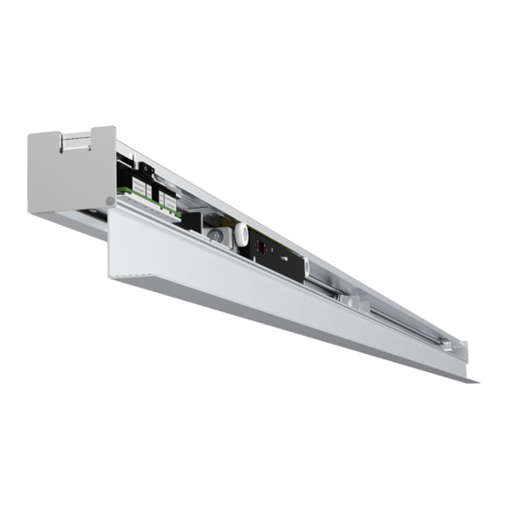
1. EVODRIVE+ COMPONENT OVERVIEW Side Covers Power Supply Circuit I/O Module - Master Aluminium Cover Profile Linear Motor Type LSMPM Motor Driver Leaf Trolleys Permanent Neodymium Magnets Aluminium Main Profile End Stops INSTALLATION MANUAL... - Page 13 INSTALLATION MANUAL...
-
Page 14: Verify The Opening Direction And The Operator Length
2. VERIFY THE OPENING DIRECTION AND THE OPERATOR LENGTH RIGHT SIDE OPENING (From the operator side) LEFT SIDE OPENING (From the operator side) INSTALLATION MANUAL... -
Page 15: Mounting The Operator
3. MOUNTING THE OPERATOR 3.1. SINGLE LEAF DOOR: MEASURE THE OPENING WIDTH AND HEIGHT *DL= TD + SW+ (A1 + A2) LEGEND DL = Drive Length COW = Clear Opening Width D1/D2 = Overlap OH = Opening Height SW = Width of Sliding Leaf D3 = Door Handle Distance OW = Opening Width TD = Travelling Distance... -
Page 16: Double Leaf Door: Measure The Opening Width And Height
3.2. DOUBLE LEAF DOOR: MEASURE THE OPENING WIDTH AND HEIGHT DL= 2x(SWL + TD) + (A1+A2) SWLS LEGEND DL = Drive Length OH = Opening Height OW = Opening Width COW = Clear Opening Width SWL / SWR = Width of Left Sliding Leaf / Right Sliding Leaf TDL / TDR = Travelling Distance Left Sliding Leaf / Right Sliding Leaf D1 = Overlap D2 = Door Handle Distance... -
Page 17: Preparations Before Mounting
3.3. PREPARATIONS BEFORE MOUNTING d = 200 mm WALL MOUNT IRON BEAM MOUNT D1+A1 D1= Leaf Overlap A1= Header Extension WALL MOUNT MOUNT TO IRON BEAM (Recommended) DIN 7982 4/5x25 DIN 6923 M6 DIN 7972 G25 (Recommended) (Recommended) (Recommended) INSTALLATION MANUAL... -
Page 18: Types Of Leaf Adapters
3.4. TYPES OF LEAF ADAPTERS WOODEN LEAF (40 mm) ALUMINIUM LEAF (44 mm) FULL GLASS (8-12 mm) 8-12 8-12 10 10 10 10 TWINS (8-12 mm) SV-EASY (8-10 mm) TOP RAIL (8-10 mm) 8-10 8-10 8-10 8-10 8-12 8-12 10 10 *Recommended height INSTALLATION MANUAL... -
Page 19: Location Of The Activators And Connection To Mains
3.5. LOCATION OF THE ACTIVATORS AND CONNECTION TO MAINS ACTIVATORS ≥ 20 mm CONNECTION TO MAINS DETAIL A > 20 mm INSTALLATION MANUAL... -
Page 20: Mounting The Door Leaves
4. MOUNTING THE DOOR LEAVES 4.1. TIMBER LEAF ADAPTER: MOUNT THE ALUMINIUM PROFILE ONTO THE WOOD PANEL LPH= SW - 10 5 mm 5 mm 50 100 LPH = Adapter Length SW = Sliding Leaf Width 4.2. SLIDE THE LEAF CONNECTOR RODS INTO THE ADAPTER INSTALLATION MANUAL... -
Page 21: Attach The Leaf Connector Rods To The Trolleys
4.3. ATTACH THE LEAF CONNECTOR RODS TO THE TROLLEYS 1. Identify the correct position of the leaf connectors V+ 0V R1 R2 S1 S2 T1 T2 V+ 0V A1 V+ 0V A2 V+ 0V R1 R2 S1 S2 T1 T2 Exterior Sensor Ext. -
Page 22: Adjust The Door Leaf
4.4. ADJUST THE DOOR LEAF HEIGHT ADJUSTMENT DEPTH ADJUSTMENT No. 13 No. 13 Min. 8 mm Max. 23 mm 4.5. FINAL ADJUSTMENT After the door leaf has been put in place and sliding on its floor guide, and right before running the self-adjustment, loose the nut that connects the front trolley with the motor, slide the door two times to full open and full close positions, and tighten the nut again firmly. -
Page 23: Connect The Accessories
5. CONNECT THE ACCESSORIES 5.1. HOW TO INSTALL AND CONNECT THE AUTOMATIC LOCK (OPTIONAL) Automatic lock wiring to the I/O module LEFT OPENING DOOR RIGHT OPENING DOOR INSTALLATION MANUAL... -
Page 24: Wiring And Commissioning
6. WIRING AND COMMISSIONING 6.1. CONNECT THE POWER CABLE Before you connect the operator to mains, all the accessories and devices must be already wired to the I/O module. The power supply circuit in the EvoDrive+ is compatible with 110V and 220/230V. I/O Module Power Supply Circuit BROWN (phase) -
Page 25: Push Button (Wired Version)
6.3. PUSH BUTTON (WIRED VERSION) Make sure that the operator is switched OFF, and the door is disconnected from the mains, before wiring any accessory to the I/O module. V+ 0V R1 R2 S1 S2 T1 T2 V+ 0V A1 V+ 0V A2 V+ 0V R1 R2 S1 S2 T1 T2 Exterior Sensor... -
Page 26: Activation And Safety Sensor
6.5. ACTIVATION AND SAFETY SENSOR Make sure that the operator is switched OFF, and the door is disconnected from the mains, before wiring any accessory to the I/O module. V+ 0V R1 R2 S1 S2 T1 T2 V+ 0V A1 V+ 0V A2 V+ 0V R1 R2 S1 S2 T1 T2 Exterior Sensor... - Page 27 6.5.3. OPTEX OAM-DUAL T Activation and Safety Sensor (Exterior / Interior) Make sure that the operator is switched OFF, and the door is disconnected from the mains, before wiring any accessory to the I/O module. V+ 0V R1 R2 S1 S2 T1 T2 V+ 0V A1 V+ 0V A2 V+ 0V R1 R2 S1 S2 T1 T2...
-
Page 28: Public Toilet Mode
6.6. PUBLIC TOILET MODE To set up the door in toilet mode: · An optional I/O module must be ordered, and delivered with the main control board. It cannot be added after delivery. · The parameter “0 - Operating mode”, must be set to “5 - Public Toilet Mode”. See point 8 in this manual for further details. -
Page 29: Remote Control (Operating Mode Selector)
6.7. REMOTE CONTROL (OPERATING MODE SELECTOR) Every EvoDrive+ automatic door operator is delivered with a Remote Control that has been paired before delivery. Use this instructions ONLY for new or additional remote controls. AUTOMATIC mode Every time an activation device (push button, OPEN mode touchless switch, radar or sensor) is triggered The door will open and remain free. -
Page 30: Wireless Push Button
6.8. WIRELESS PUSH BUTTON If the EvoDrive+ automatic door operator is delivered with a Wireless Push Button, this has been paired before delivery. Use this instructions ONLY for new or additional push buttons. SINGLE SLIDING DOOR DOUBLE LEAF SLIDING DOOR Pair the wireless push button Pair the wireless push button with the with the motor... -
Page 31: Self-Adjustment After Installation
7. SELF-ADJUSTMENT AFTER INSTALLATION This process must be carried out after the door has been installed, and every time the door leaf has been re-adjusted, or the position of the end stops has changed. The self-adjustment computes the weight of the leaf and the opening width and does not override the parameters programmed by the service technician. -
Page 32: Configuration Of The Basic Parameters
8. CONFIGURATION OF THE BASIC PARAMETERS To set any of the parameters in the list below: +5 s (+) UP (-) DOWN Enter the configuration mode: press and hold Press (+) or (-) to navigate through the different buttons (+) and (-) simultaneously during 5 parameters, until you reach the desired sec., then release. - Page 33 Hold Open Time. Sets the length of time that the door remains open before closing after being activated, in Automatic or Exit Only Modes (Note: parameters 05 and 06 must be set to “0”). Set to: ‘0’. ca. 0 sec - Default Value ‘1’.
- Page 34 Push&Go / Push-to-open and Push to close. Sets the reaction of the door after the leaf or door handle has been pushed manually, in Automatic and Exit Only modes. Set to: ‘0’. Push / Go / Normal Mode. The door opens and closes automatically after pushing the leaf or door handle manually 5 cm in the opening direction - Default Value ‘1’.
- Page 35 RESERVED. DO NOT CHANGE Opening Direction. Before running the self-adjustment, set the door opening to: ‘0’. Left. The door opens from right to left ‘1’. Right. The door opens from left to right Bluetooth Pairing. Use this parameter only when you change the motor and/or I/O module with a new one, and you need to pair them.
-
Page 36: Description Of The Led Indicators On The I/O Module
9. DESCRIPTION OF THE LED INDICATORS ON THE I/O MODULE I/O MODULE Lock Lock Bluetooth Int. Switch Ext. Switch Int. Sens. Int. Sensor Power Bluetooth LED INDICATORS LEDs DESCRIPTION POWER ON when the operator is energized ON after switching the power on OFF in normal working mode BLUETOOTH Fast BLINK in pairing connection process... -
Page 37: Malfunction Codes
10. MALFUNCTION CODES In case of malfunction, a numeric code will BLINK on the motor two-digit display. Description: Motor Overcurrent Action: Switch the operator off and on again. If the error persists, call an official service technician. Description: Encoder Malfunction Action: Verify the presence of magnets above the full length of the motor, along the entire travelling movement;... - Page 38 Description: Bluetooth communication is misssing between the motor and I/O module Action: Pair the motor and I/O module back together. Description: Problem on the electronic board clock Action: Switch the operator off and on again. If the error persists, call an official service technician.
-
Page 39: Evodrive+ Installation Checklist
11. EVODRIVE+ INSTALLATION CHECKLIST End user: _______________________________________________ Operator serial number:___________________________________ Address: _______________________________________________ Zip code: _______________________________________________ City: _______________________________________________ Country: _______________________________________________ Basic operation Complies Doesn’t comply Not applicable Comments Self-adjustment Push & Go Push button Remote control Operating modes Complies Doesn’t comply Not applicable Comments Automatic... -
Page 40: Declaration Of Conformity Ce
12. DECLARATION OF CONFORMITY CE (Directive 2006/42/EC - Directive on Machinery) Installer: Address: Declares that: Door description: (Model, type) Serial number: Installed in (location): (Serial number of EvoDrive+) (Client, address) • The installation is conform to the requirements set in the Directive of Machinery 2006/42/EC. •... - Page 42 ADDRESS CONTACT Linear Motor Applications, S.L. Tel.: +34 935 624 639 Pol. Ind. Santiga E-mail: info@motion4.eu Pasaje Arrahona 4, Nave 1 www.motion4.eu 08210 Barberà del Vallès Barcelona, España...
- Page 43 EvoDrive+ USER MANUAL Part 3 of the Installation, User and Maintenance Manual This section must be given to the User of the automatic door v3.0.0...
- Page 44 INDEX PART 3 USER MANUAL 1. PRODUCT DESCRIPTION ........................4 2. INSTRUCTIONS OF USE ........................4 2.1. OPERATING MODES ................................4 2.2. OPERATION DURING POWER FAILURE ..........................4 2.3. DOOR CLEANING ..................................5 2.4. RESTRICTIONS OF USE .................................5 3. RISK ASSESSMENT ..........................6 3.1. IDENTIFICATION OF DANGEROUS AREAS ........................6 3.2.
- Page 45 PART 3 User manual This part of the manual explains the operating and safety considerations, to be taken into account by the end user. It is very important to read this manual in full, and to observe and follow all instructions as described herein.
- Page 46 1. PRODUCT DESCRIPTION This door is equipped with the EvoDrive+ automatic sliding door operator, specifically designed for interior doors. Equipped with the latest technology in automatic doors, the leaves are moved by a linear motor that slides with the door leaf by attraction and repulsion of the permanent magnets incorporated along the header frame, making the operator a very compact unit, with a superb, smooth and silent movement.
- Page 47 2.3. DOOR CLEANING To clean the door, press button “Open” on the remote control to set the door to “Open” mode, then slide the door leaf manually to any position. In this mode, the activation devices will remain disabled, and the door is safe for cleaning.
- Page 48 Only authorized technicians are allowed to open the cover of the door operator and manipulate the internal parts, for installation and maintenance purposes. The power switch must be turned off before doing any intervention on the door operator. End users and non-qualified technicians are strictly not allowed to open the cover and/or manipulate the internal parts of the door operator.
- Page 49 IMPACT CRUSH SHEARING ENTRAPMENT HOOKING USER MANUAL...
- Page 50 3.2. RESIDUAL RISKS Although the EvoDrive+ automatic door operator has been designed and manufactured to ensure a safe operation, some residual risks may still persist even after adopting complementary measures of protection. Automatic sliding doors may have some risks of crush, impact, entrapments and other potential hazzards. Depending on the structural conditions on site, the door version and the safety equipment, these risks may not disappear completely.
- Page 51 5. TECHNICAL SPECIFICATIONS MECHANICAL FEATURES Clear opening width, single leaf (mm): 750 - 1400 Clear opening width double leaf (mm): 1500 - 2800 Operator length, single leaf (mm): 1650 - 2850 Operator length double leaf (mm): 3100 - 5700 MAIN FEATURES Opening speed: adjustable between 200 and 600 mm/s Closing speed: 200 mm/s EN16005 “Low Energy”...
- Page 52 6. AUTOMATIC DOOR OPERATOR CE DECLARATION FORM DECLARATION OF CONFORMITY Directive 2006/42/CE -Directive on Machinery- We hereby declare, under our sole responsibility, that the product and model described here in is conform to the essential health and safety requirements as described in the following directives issued by the European Council for the harmonisation of the legal norms in all countries members of the European Union: Product: Automatic door operator for sliding doors...
- Page 53 ADDRESS CONTACT Linear Motor Applications, S.L. Tel.: +34 935 624 639 Pol. Ind. Santiga E-mail: info@motion4.eu Pasaje Arrahona 4, Nave 1 www.motion4.eu 08210 Barberà del Vallès Barcelona, Spain...
- Page 54 EvoDrive+ MAINTENANCE MANUAL Part 4 of the Installation, User and Maintenance Manual This section must be given to the Owner of the automatic door, and be always available for the Maintenance technician v3.0.0...
- Page 55 INDEX PART 4 MAINTENANCE MANUAL 1. INTRODUCTION ...........................4 2. EVODRIVE+ COMPONENT OVERVIEW ..................5 3. TECHNICAL SPECIFICATIONS ......................6 4. BASIC TROUBLESHOOTING ......................7 5. MALFUNCTION CODES ........................8 6. DESCRIPTION OF THE LED INDICATORS ON THE I/O MODULE ...........10 7. MAINTENANCE INTERVALS .......................11 8.
- Page 56 PART 4 Maintenance Manual This part of the manual explains the considerations for the correct maintenance of the operator. It is very important to read this manual in full, and to observe and follow all instructions as described herein.
- Page 57 1. INTRODUCTION The maintenance of the EvoDrive+ automatic sliding door operator must be done only and exclusively by qua- lified and skilled technicians, bearing the necessary technical and professional accreditations, as required by the laws in force in the country of installation, and using only and exclusively the original spare parts and com- ponents supplied by Linear Motor Applications, S.L., or otherwise those expressly approved by them.
- Page 58 2. EVODRIVE+ COMPONENT OVERVIEW Side Covers Power Supply Circuit I/O Module - Master Aluminium Cover Linear Motor Type LSMPM Motor Driver Leaf Trolleys Permanent Neodymium Magnets Main Profile End Stops MAINTENANCE MANUAL...
- Page 59 3. TECHNICAL SPECIFICATIONS MECHANICAL FEATURES Clear Opening Width, single leaf (mm): 750 - 1400 Clear Opening Width double leaf (mm): 1500 - 2800 Operator Length, single leaf (mm): 1650 - 2850 Operator Length double leaf (mm): 3100 - 5700 MAIN FEATURES Opening Speed: adjustable between 200 and 600 mm/s Closing speed: 200 mm/s EN16005 “Low Energy”...
- Page 60 4. BASIC TROUBLESHOOTING SITUATION / PROBLEM SOLUTION Check and remove obstructions in the closing travelling area. Check that leaf can be moved manually and smoothly. Obstruction detection during the closing cycle In the event of having sensors installed, verify that the sensors are adjusted so that the door is not detected by them.
- Page 61 5. MALFUNCTION CODES In case of malfunction, a numeric code will BLINK on the motor two-digit display. Description: Motor Overcurrent Action: Switch the operator off and on again. If the error persists, call an official service technician. Description: Encoder Malfunction Action: Verify the presence of magnets above the full length of the motor, along the entire travelling movement;...
- Page 62 Description: Bluetooth communication is misssing between the motor and I/O module Action: Pair the motor and I/O module back together. Description: Problem on the electronic board clock Action: Switch the operator off and on again. If the error persists, call an official service technician.
- Page 63 6. DESCRIPTION OF THE LED INDICATORS ON THE I/O MODULE I/O MODULE Lock Lock Bluetooth Int. Switch Ext. Switch Int. Sens. Int. Sensor Power Bluetooth LED INDICATORS LEDs DESCRIPTION POWER ON when the operator is energized ON after switching the power on OFF in normal working mode BLUETOOTH Fast BLINK in pairing connection process...
- Page 64 7. MAINTENANCE INTERVALS In the following chart we show the tasks and intervals of the interventions that are required to periodically execute on the EvoDrive+ automatic door operator, which depends on the frequency or the number of cycles: TASK FREQUENCY NUMBER OF CYCLES Cleaning of the top and bottom track rails Yearly...
- Page 65 8. MAINTENANCE RECORD SHEET Date: Made by: (name of the service technician) Complies: Remarks: Signed by the Signed by the service client: Technician: Date: Made by: (name of the service technician) Complies: Remarks: Signed by the Signed by the service client: Technician: Date:...
- Page 66 Date: Made by: (name of the service technician) Complies: Remarks: Signed by the Signed by the service client: Technician: Date: Made by: (name of the service technician) Complies: Remarks: Signed by the Signed by the service client: Technician: Date: (name of the service technician) Made by: Complies: Remarks:...
- Page 67 ADDRESS CONTACT Linear Motor Applications, S.L. Tel.: +34 935 624 639 Pol. Ind. Santiga E-mail: info@motion4.eu Pasaje Arrahona 4, Nave 1 www.motion4.eu 08210 Barberà del Vallès Barcelona, España...
Need help?
Do you have a question about the EvoDrive+ and is the answer not in the manual?
Questions and answers