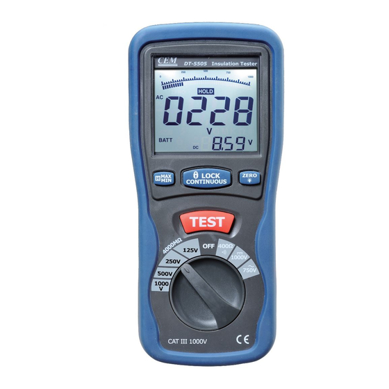
Summary of Contents for CEM DT-5505
- Page 1 IGITAL INSULATION TESTER NSTRUCTION MANUAL Insulation Tester DT-5 505 (1 ) (1 ) POL1 LOBAT (1 ) (2 ) POL2 (2 ) (2 ) TEST 125V 250V 1000V 500V 750V 1000V...
-
Page 2: Safety Information
SAFETY INFORMATION Read the follow ing safety information carefully before attempting to operate or service the meter. To avoid damages to the instrument do not apply the signal s whi c h exceed the maximum limits shown in the technical specifications tables. -
Page 3: Specifications
Safety symbols: Caution refer to this manual before using the meter. Dangerous voltages. Meter is protected throughout by double insulation or reinforced insulation. When servicing, use only specified replacement parts. CE Comply w ith EN-61010-1 1. SPECIFICATIONS 1-1 General Information Environm ent conditions: ①... - Page 4 1000V/DCV. ,750V/ACV Sam pling Rate: 2.5 times per second. Zero Adjustment: Automatic adjustment. Over Range Indicator: “OL” of highest digit is displayed. Low Battery Indication: The is displayed w hen the battery Voltage drop below the operating voltage. Operating Temperature: 0ºC to 40ºC (32ºF to 104ºF) and Humidity below 80% RH Storage Temperature: -10ºC to 60ºC (14ºF to 140ºF) and Humidity below 70% RH...
- Page 5 Ω Ω •))) 0.01 Resistance≤35 5.8V 250Vrms ≧200mA Short circuit current DC Voltage Range Resolution Accuracy Input Overload Impedance Protection 1000V +(0.8%+3) 10MΩ 1000Vrms AC Voltage (40Hz~400Hz) Range Resolution Accuracy Input Overload Impedance Protection 750V +(1.2%+10) 10MΩ 750Vrms Meg OHMS Test Short Terminal...
-
Page 6: Parts And Controls
Ω Ω 400.1~4000 M +(4%+5) Ω Ω ≤ 1000V 1.000~4.000 M 0.001M +(3%+10) Ω Ω @load (0%~+1 4.001~40.00 M 0.01M +(2%+10) Ω Ω 1MΩ 40.01~400.0 M 0.1M +(2%+5) Ω Ω 400.1~4000 M +(4%+5) 2. PARTS & CONTROLS 1.Digital Display 2.Data Hold Button; MAX/MIN Insulation Tester DT-5 505 3.Lock Button... - Page 7 alligator clip of the test leads connected. The indicator should read 00.0Ω. When the leads are not connected the display w ill read infinity indicated by “OL”. This w ill ensure that test lead are under w orking condition. 2-4 Rotary Sw itch positions Turn the Tester on by selecting any measurement Lift <...
- Page 8 if in the 2nd time. pressing for 2 seconds, it will enter directly into the “LIGHT” status, and the LCD backlight light up. After 15 seconds, the backlight is shut off automatically, the same as pressing for 2 seconds within 15s. Display Indicators The Primary Display:Indicate the current function testing values The Secondary Display:...
-
Page 9: Insulation Resistance Measurements
3. INSULATION RESISTANCE MEASUREMENTS a)Turn the function switch from the “OFF” position to the left(4000 MΩ/1000V---4000/ MΩ500V---4000 MΩ/250V---1000 MΩ/125V) ,and chose one of the voltage-block( there are 4 ranges namely, 4 MΩ40 MΩ400 MΩ4000 MΩ, can be sw itched automatically for every voltage-block.) b)Connect tw o testing lines to the tested;... -
Page 10: Ac/Dc Voltage Measurements
4.LOW RESISTANCE (CONTINUITY) MEASUREMENTS a). Set the range sw itch to 400Ω/BZ Position b). Connect the red test lead to the V Ω terminal and black to the COM terminal. c). Connect the tips of the test leads to both ends of the circuit under test. -
Page 11: Battery Saver (Sleep Mode)
6.BATTERY SAVER (SLEEP MODE) The meter w ill automatically enter the “sleep mode” if there is no function change or button press for 10minutes, but it w orks as soon as you turn the rotary function switch or push down any button 7.POWER TOOLS AND AMALL APPLIANCES This test w ould also apply to other similar equipment that has a line cord. - Page 12 armature, field coils and brush rigging by connecting one megohmmeter lead to each of them individually, leaving the other connected to the grounded motor housing. The above also applies to DC Gemerators.
- Page 13 CABLES Disconnect the cable from the line. Also disconnect opposite end to avoid errors due to leakage from other equipment. Check each conductor to ground and /or lead sheath by connecting one megohmmeter lead to a ground and /or lead sheather and the other megohmmeter lead to each of the conductors in turn.


Need help?
Do you have a question about the DT-5505 and is the answer not in the manual?
Questions and answers