Table of Contents
Advertisement
Quick Links
Advertisement
Table of Contents

Related Manuals for Inspur NF5486M5


Summary of Contents for Inspur NF5486M5
- Page 1 Inspur Server User Manual NF5486M5...
- Page 2 Inspur. The information in this manual is subject to change without notice. Inspur is the registered trademark of Inspur. All the other trademarks or registered trademarks mentioned in this manual are the property of their respective holders.
- Page 3 4.Please install the product-compatible operating system and use the driver provided by Inspur. If you use an incompatible operating system or non-Inspur driver, it may cause compatibility issues and affect the normal use of the product, Inspur will not assume any responsibility or liability.
-
Page 4: Table Of Contents
Contents 1 Safety Instructions ......................... 1 2 Product Specification ........................5 2.1 Introduction ..........................5 2.2 Features and Specifications ......................6 3 Component Identification ......................8 3.1FrontPanel Components ......................8 3.2 Rear Panel ........................... 10 3.3 MotherboardComponents ......................11 4 Operations ............................. 13 4.1 Power up the Server ........................ - Page 5 6.3Memory Option ........................... 25 6.4Hot-plug HDDOption ........................27 6.5Air Baffle Option .......................... 29 7 BIOS Setup ............................. 31 7.1 Common Operations ........................31 7.2 BIOS Parameter Description ....................... 48 7.3 Firmware Update ........................89 8 BMC Settings ..........................94 8.1 Introduction ..........................94 8.2 Functional Modules ........................
- Page 6 11.5 Chinese Notice.......................... 133 11.6 Battery Replacement Notice ....................133 12 Electrostatic Discharge ........................ 134 12.1 Preventing Electrostatic Discharge ................... 134 12.2 Grounding Methods to Prevent Electrostatic Discharge ............134 13 Warranty ............................135 13.1 Introduction ..........................135 13.2 Warranty Service ........................135 13.3 Warranty Exclusions .........................
-
Page 7: Safety Instructions
For your safety, please do not attempt to remove the cover of the system to remove or replace any component without assistance provided by Inspur. Only service technicians trained by Inspur are authorized to remove the cover of the host, and to remove and replace internal components. - Page 8 In the event of the following, please unplug the power line plug from the power socket and contact Inspur’s customer service department: The power cables, extension cables or power plugs are damaged.
- Page 9 Please remember that only service technicians trained by Inspur are authorized to remove the cover of the host, and to remove and replace internal components.
- Page 10 Upon receiving the proper authorization from Inspur and dismounting the internal components, please pay attention to the following: Switch the system power supply off and disconnect the cables, including all connections of the system.
-
Page 11: Product Specification
Intelligent monitoring of energy consumption, dynamic control of hard drives NF5486M5 can control the power-on and power-off of a single hard drivethrough hardware structure design. Users can flexibly shut down the power supply of any hard drive through the management interface (BMC console) according to business needs to save energy and save the operating costs of the server room. -
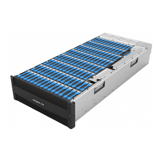
Page 12: Features And Specifications
3.5×10⁶ configuration (e.g. full configuration) The server supports 106 3.5-inch SATA hard drives, and the appearance is shown below. 2.2 Features and Specifications Technical specifications Model NF5486M5 Hardware features Controller One controller and dual CPUs, do not support hot swap Host Standard 4U rack server, which can be placed in a 1.2m rack... - Page 13 Product Specification Front (chassis ear): POWER button, RESET button, UID LED, HDD LED, fan LED and system status LED Port Rear: OneRJ45 + oneVGA+ two USB.3.0 Microsoft Windows Server 2008/2012/2016 Operating system Red Hat Enterprise Linux 6/7 SUSE Linux Enterprise Server 11/12 Physical features Chassis dimensions W*D*H 447*995*174mm...
-
Page 14: Component Identification
3 Component Identification 3.1FrontPanel Components Item Description Front panel buttons& LEDs HDD & Fan LEDs Front Panel Buttons and LEDs Item Description Power button ID LED& button Reset button... - Page 15 Component Identification HDD & Fan LEDs Item Description HDD failure LED (1st row) HDD failure LED (2nd row) HDD failure LED (3rd row) HDD failure LED (4th row) HDD failure LED (5th row) HDD failure LED (6th row) HDD failure LED (7th row) HDD failure LED (8th row) 40FAN0 failure LED 40FAN1 failure LED...
-
Page 16: Rear Panel
3.2 Rear Panel Item Description 6076 system fan 0 6076 system fan 1 6076 system fan 2 6076 system fan 3 PSU0 PCIe slot BMC management port USB3. 0 port VGA port OCP slot Main power switch PUS1 6076 system fan 7 Left rear cover of the HDD tray 6076 system fan 6 6076 system fan 5... -
Page 17: Motherboardcomponents
Component Identification 3.3 MotherboardComponents Item Description Power button OCP slot A TPM connector DIMM slots (CPU0) CPU0 socket CPU1 socket DIMM slots (CPU1) Signal backplane connector Power backplane connector M. 2 connector OCP slot C PCIe x16 slot BMC network port USB port VGA port UID LED... - Page 18 Item Description Function Short-circuit pin1-2,normal status; CLR_CMOS CMOS clear jumper Short-circuit pin2-3, clear CMOS. Note: It is required to shut down the system, as well as disconnect the power supply during CMOS clearing.Hold for 5 seconds after short-circuiting pin2-3.
-
Page 19: Operations
Operations 4 Operations 4.1 Power up the Server Insert the power cord plug, then press the Power Button. 4.2 Power down the Server WARNING: To reduce the risk of personal injury, electric shock, or damage to the equipment, remove the power cord to remove power from the server. The front panel Power Button does not completely shut off system power. -
Page 20: Remove The Access Panel
WARNING: To reduce the risk of personal injury or equipment damage, be sure that the rack is adequately stabilized before extending a component from the rack. After performing the installation or maintenance procedure, align the server with the rails, and slide the server back into the rack. WARNING: To reduce the risk of personal injury, be careful when sliding the server into the rack. -
Page 21: Install The Access Panel
Operations Extend the server from the rack. Loosen the two security screws on the front of the access panel by hand, and remove the front access panel. Lift up on the hood latch handle, and then remove the rear access panel. 4.5 Install the Access Panel Place the front access panel on the server. -
Page 22: Remove The Motherboard Tray, Psu And 6076 System Fan
Open the hood latch, place the rear access panel on the server, and align the guide pins on both sides with the corresponding guide slots on the chassis base. Align the hole on the hood latch with the alignment pin in the chassis and push the hood latch to the closed position. -
Page 23: Remove The 4056 System Fan
Operations Press the lock button①, push the top cover in the direction of ②, and remove the top cover of the motherboard tray. Remove the air baffle above the motherboard as shown below. 4.8 Remove the 4056 System Fan CAUTION: For proper cooling, do not operate the supercomputer without the access panel, air baffle, or fan installed. - Page 24 Remove the fan bracket from the chassis as shown by ③, and remove the fan as shown by ④.
-
Page 25: Setup
Setup 5 Setup 5.1 Optimum Environment When installing the server in a rack, select a location that meets the environmental standards described in this section. 5.1.1 Temperature Requirements To ensure continued safe and reliable equipment operation, install or position the system in a well-ventilated, climate-controlled environment. -
Page 26: Identifying The Contents Of The Server Shipping Carton
Because of the high ground-leakage currents associated with multiple servers connected to the same power source, Inspur recommends the use of a PDU that is either permanently wired to the building’s branch circuit or includes a nondetachable cord that is wired to an industrial-style plug. -
Page 27: Installing Hardware Options
Setup In addition to the supplied items, you may need: • Operating system or application software • Hardware options 5.3 Installing Hardware Options Install any hardware options before initializing the server. For options installation information, refer to the option documentation. For server-specific information, refer to “Hardware options installation”. -
Page 28: Installing The Operating System
5.5 Installing the Operating System To operate properly, the server must have a supported operating system installed. For the latest information on supported operating systems, refer to the Inspur website (http://www. inspur.com/eportal/ui?pageId=2317460).To install an operating system on the server, you... -
Page 29: Hardware Options Installation
Hardware Options Installation 6 Hardware Options Installation 6.1 Introduction If more than one option is being installed, read the installation instructions for all the hardware options and identify similar steps to streamline the installation process. WARNING:To reduce the risk of personal injury from hot surfaces, allow the drives and theinternal system components to cool before touching them. - Page 30 6.Install the processor: Step 1:Align the Clip’s triangle mark with the CPU’s corner mark, and then assemble the Clip and CPU together. Step 2:Align the heatsink position marked by “1” with the Clip’s triangle mark, vertically align the mounting holes on the heatsink with those on the Clip, and assemble the heatsink andClip together.
-
Page 31: Memory Option
Hardware Options Installation Step 3: Install the assembled heatsink module onto the CPU socket, and the position marked by “1” should be aligned with the triangle mark on the CPU socket. Tighten the screws according to the sequence of 1, 2, 3 and 4. Notes: ●... - Page 32 ● DIMM population guidelines: Two CPUs: CPU1 CPU0 DIMM CH5 CH4 CH1 CH2 CH5 CH4 CH1 CH2 D0 D0 D0 D1 D1 D0 D0 D0 D0 D0 D0 D1 D1 D0 D0 D0 ● ● ● ● ● ● ● ●...
-
Page 33: Hot-Plug Hddoption
Hardware Options Installation DIMM installation method: Step 1: Open the lock tabs on both ends of the DIMM slot. Step 2: Align the bottom key with the receptive point on the slot, press both ends of the DIMM with your thumbs. Insert the DIMM into the slot completely, and the lock tabs will automatically secure the DIMM, locking it into place. - Page 34 Step 2:Pull the two sides of the tray outward as shown by ④, and remove the HDD as shown by⑤. Step 3:Place the HDD at a 45-degree angle into the tray, the screw holes on the HDD aligned with the locating pins on the tray. Press the HDD downward to secure it into the tray.
-
Page 35: Air Baffle Option
Hardware Options Installation Step 4: Install the tray into the server. 6.5 Air Baffle Option CAUTION:For proper cooling, do not operate the server without the access panel, baffles, expansion slot covers, or blanks installed. If the server supports hot-plug components, minimize the amount of time the access panel is open. - Page 36 Remove the air baffle vertically, and replace it with a new one.
-
Page 37: Bios Setup
Power on the server. The system will then start to boot. When the following content appears below Inspur logo on the screen: “Press <DEL> to SETUP or <TAB> to POST or <F11> to Boot Menu or <F12> to PXE Boot.” Press DEL key. When “Entering Setup …” appears in the lower right corner of the screen, it will enter the BIOS setup soon. - Page 38 • Press F11 to enter the boot management interface, select the boot device. • Press F12 to boot the PXE. BIOS Setup Interface Control Key Instruction Table Function <Esc> Exit or return from submenu to main menu <←> or <→> Select a menu <↑>...
- Page 39 Network, Storage, Video OPROM Policy and Other PCI devices, as shown in the following figure. At present, Inspur Purley platform servers are set to UEFI Mode by default. Compared with Legacy mode, UEFI mode has many advantages: It supports boot from the GPT disk which is larger than 2.2T, supports IPv6/IPv4 PXE boot, and provides UEFI Shell environment.
- Page 40 7.1.4 View CPU Information Login to the BIOS interface, select “Processor -> Processor Configuration -> Processor Information”, and press Enter to display the CPU detailed information, as shown in the following figure. 7.1.5 View Memory Information Login to the BIOS interface, select “Processor -> Memory Configuration -> Memory Topology”, and press Enter to display the manufacturer, speed, capacity and other...
- Page 41 BIOS Setup information of the memories in position, as shown in the following figure. 7.1.6 View HDD Information and RAID Configuration 7.1.6.1 View HDD Information Login to the BIOS interface, select “Chipset -> PCH SATA Configuration/PCH sSATA Configuration”, and press Enter to display the HDD information of the current onboard SATA ports or sSATA ports, as shown in the following figures.
- Page 42 7.1.6.2 RAID Mode Settings Set the SATA Mode Option to [RAID], press F10 to save the setting, and the system reboots. When Boot Mode is set to UEFI mode, in the BIOS Setup Advanced interface, there will be the Intel(R) RSTe SATA Controller menu, as shown in the following figure. Press Enter, the executable operation and the current disk information will be displayed,...
- Page 43 BIOS Setup as shown in the following figure. Create RAID volume. Select Create RAID Volume option, and press Enter, as shown in the following figure.
- Page 44 Create RAID Menu Instruction Table Interface Parameters Function Description Please enter a volume name less than 16 characters without containing any special Name characters. Please select the RAID volume level. If no volume has been created at present, there are four volume levels of RAID0 (Stripe), RAID1 (Mirror), RAID10 (RAID0+1) and RAID5 (Parity) for selection.
- Page 45 BIOS Setup When Boot Mode is set to Legacy, a prompt “Press <CTRL-I> to enter Configuration Utility…” will appear on the screen during system booting. Press [Ctrl] and [I] keys at the same time to enter SATA RAID configuration, as shown in the following figure. After entering SATA RAID configuration interface, it will display the main menu list, the information (disk ID, disk type, disk capacity, volume member or not) of disks connected to SATA controller, and the existed RAID volumes information (including volume ID, name, RAID...
- Page 46 Key Instruction Table Description ↑↓ Used to move cursor in different menus or to change values of menu options To select the next menu option Enter To select a menu To exit menu or return to previous menu from sub-menu Menu Instruction Table Create RAID Volume To create an RAID volume...
- Page 47 BIOS Setup Create RAID Menu Instruction Table Interface Parameters Function Description Please enter a volume label name less than 16 characters without containing any Name special characters. Please select RAID volume level. If no volume has been created at present, there are four volume levels of RAID0 (Stripe), RAID1 (Mirror), RAID10 (RAID0+1) and RAID5 (Parity) for selection.
- Page 48 Reset Disks to Non-RAID menu. After entering Reset Disks to Non-RAID menu, system will display all disks in RAID volume. Please use the space key to select the disk to reset according to the actual demand, and then press Enter to reset the disk. The system will prompt “Are you sure you want to reset RAID data on selected disks? (Y/N)”...
- Page 49 BIOS Setup Exit menu. Select Exit menu through up and down keys, or press ESC to exit SATA RAID configuration interface, as shown in the following figure. The system will prompt “Are you sure you want to exit? (Y/N)”, enter “Y” to exit, or enter “N” to cancel the exit operation. 7.1.7 View and Set BMC Network Parameters 7.1.7.1 View BMC Network Parameters Login to the BIOS interface, select “Server Mgmt ->...
- Page 50 7.1.7.2 BMC Network Settings Take BMC Sharelink port as an example to introduce the settings of BMC IPv4 network parameters, as shown in the following table. BMC Network Configuration Instruction Table Interface Parameters Function Description Default Value Set the way to get BMC network parameters, options include: Get BMC Sharelink /Dedicated Do Nothing...
- Page 51 BIOS Setup will prompt “Set Static BMC IP Address Source Success!!”, as shown in the following figure. Select the Station IP Address option. Press Enter, the Station IP Address window pops up. Input the Static IP manually. After the setting is completed, press Enter to confirm, as shown in the following figures:...
- Page 52 If the setting succeeds, the system prompts “Set Static BMC Station IP OK!!!” Press Enter to confirm, and the IP will take effect immediately. If the setting fails, the system prompts “Set Static BMC Station IP Fail!!!” If the IP does not change, the system prompts “Static BMC Station IP Not Change!!!” If the input IP is invalid, the system prompts “Invalid Station IP Entered!!!”, and assign 0.0.0.0 to the IP address.
- Page 53 BIOS Setup After pressing Enter to confirm, the following interface will stay for 30s, please wait patiently. After the dynamic network takes effect, the system will prompt “Get Dynamic BMC Dhcp Success!!”, and the interface will be shown as the following figure. Note: Please make sure that the BMC management port is connected to the network when you use the Manual setting options.
-
Page 54: Bios Parameter Description
The settings of BMC IPv6 network parameters are similar to this, which will be omitted here. 7.2 BIOS Parameter Description 7.2.1 Main Main interface displays the basic information of BIOS system, including BIOS/BMC/ME version, CPU type, total memory capacity and system time. Main Interface Instruction Table Interface Parameters Function Description... - Page 55 BIOS Setup 7.2.2 Advanced Advanced interface includes the BIOS system parameters and related function settings, such as ACPI, serial port, PCI subsystem, CSM, USB, onboard NIC and so on. Advanced Interface Instruction Table Interface Parameters Function Description Trusted Computing Trusted computing configuration Super IO Configuration AST2500 I/O chip parameter configuration Serial Port Console Redirection...
- Page 56 Trusted Computing Interface Instruction Table Interface Parameters Function Description Default Value Security device support settings. Options include: Enabled Disabled Security Device Support Enabled BIOS supports TPM TCG version 1.2/2.0. BIOS supports TPM module through TPM software binding, when the verification of software binding fails, BIOS will record the error to SEL.
- Page 57 BIOS Setup Super IO Configuration Interface Instruction Table Interface Parameters Function Description Serial port 0 configuration, the configuration interface provides this serial Serial Port 0 Configuration port’s on-off control and resource allocation control. Users can manually adjust the IO PORT and IRQ number that COM PORT uses. Serial Port 1 Configuration Serial port 1 configuration (virtual serial port) 7.2.2.2.1 Serial Port 0 Configuration...
- Page 58 Serial Port 0 ConfigurationInterface Instruction Table Interface Parameters Function Description Default Value Serial port 0 on-off settings. Options include: Serial Port Enabled Enabled Disabled Select the optimal setting according to the demand. Options include: Auto I0=3F8h; IRQ=4; Change Settings Auto I0=3F8h;...
- Page 59 BIOS Setup 7.2.2.4Console Redirection Settings When the Console Redirection is set to [Enabled], the Console Redirection Settings menu will be opened. Console Redirection Settings Interface Instruction Table Interface Parameters Function Description Default Value Terminal type settings. Options include: VT100 Terminal Type VT100+ ANSI VT-UTF8...
- Page 60 Flow control settings. Options include: Flow Control None None Hardware RTS/CTS VT-UTF8 combination key support on-off settings. Options include: VT-UTF8 Combo Key Support Enabled Enabled Disabled Recorder mode on-off settings. Options include: Recorder Mode Enabled Disabled Disabled Expanded redirection resolution 100×31 on-off settings.
- Page 61 BIOS Setup PCI Subsystem Settings Interface Instruction Table Interface Parameters Function Description Default Value Above 4G memory access control on-off settings. Options include: Enabled Above 4G Decoding Enabled Disabled SR-IOV support on-off settings. Options include: Enabled Enabled SR-IOV Support Disabled 7.2.2.6Network Stack Configuration Network Stack Configuration interface is used to set the options related with Network UEFI PXE.
- Page 62 Ipv6 HTTP support on-off settings. Options include: Ipv6 HTTP Support Enabled Disabled Disabled Set the wait time to cancel PXE boot after pressing ESC key, PXE boot wait time the setting range is 0~5. Media detect count Device detect count settings, the setting range is 1~50. 7.2.2.7 CSM Configuration CSM Configuration interface is used to set the options related with the compatibility support module.
- Page 63 BIOS Setup Storage device Option ROM execution mode settings. Options include: Storage Do not launch UEFI Legacy UEFI Video device Option ROM execution mode settings. Options include: Video OPROM Policy Do not launch UEFI Legacy UEFI Other PCI devices Option ROM execution mode settings. Options include: Other PCI devices Do not launch...
- Page 64 7.2.3.1 PCH SATA Configuration/PCH sSATA Configuration PCH sSATA Configuration and PCH SATA Configuration interfaces are used to set the options related with the onboard sSATA/SATA ports. Take PCH SATA Configuration menu as an example, as shown in the following figure.
- Page 65 BIOS Setup PCH SATA Configuration Interface Instruction Table Interface Parameters Function Description Default Value SATA controller on-off settings. Options include: SATA Controller Enabled Enabled Disabled SATA mode settings. Options include: SATA Mode Options AHCI AHCI RAID SATA Port 0~7 SATA port 0~7 HDD information ---- SATA port on-off settings.
- Page 66 7.2.3.3 Miscellaneous Configuration Miscellaneous Configuration interface is used to set some other common options. Miscellaneous Configuration Interface Instruction Table Interface Parameters Function Description Default Value Power state settings when restoring on AC power loss. Options include: Restore AC Power Loss Power OFF Power OFF Last State...
- Page 67 BIOS Setup Server ME Configuration Interface Instruction Table Interface Parameters Function Description Default Value Operational Firmware Version Operational ME firmware version ---- Recovery Firmware Version Recovery ME firmware version ---- ME Firmware Status #1 ME FW status value #1 ---- ME Firmware Status #2 ME FW status value #2 ----...
- Page 68 Runtime Error Logging Interface Instruction Table Interface Parameters Function Description Default Value System error log record settings. Options include: Enabled System Errors Enabled Disabled 7.2.4 Processor Processor interface is used to set the options related with the processor and memory.
- Page 69 BIOS Setup Processor Interface Instruction Table Function Description Interface Parameters Processor Configuration Processor configuration Common Configuration Common configuration UPI Configuration UPI configuration Memory Configuration Memory configuration IIO Configuration IIO configuration Advanced Power Management Configuration Advanced power management configuration 7.2.4.1 Processor Configuration Processor Configuration interface is used to set the options related with the processor.
- Page 70 The max CPUID value limit on-off settings. Enabled Max CPUID Value Limit Disabled Disabled When the legacy OS boot does not support CPUID function, please enable this option. Execute disable bit on-off setting. Options include: Execute Disable Bit Enabled Enabled Disabled Intel trusted execution technology on-off settings.
- Page 71 BIOS Setup AESinstruction on-off settings. Options include: Enabled Disabled AES-NI This menu mainly controls whether the CPU supports Enabled AES instruction. These instructions are mainly used for system virtualization. Enable this instruction, system performance will be improved. 7.2.4.2 Common Configuration Common Configuration interface is used to set the common options.
- Page 72 UPI Configuration Interface Instruction Table Interface Parameters Function Description Default Value UPI Status UPI status submenu, displaying the current UPI link status ---- Degrade precedence settings. Options include: Topology Precedence Feature Precedence Topology Degrade Precedence When the system settings conflict, set it to Topology Precedence Precedence to reduce Feature;...
- Page 73 BIOS Setup Sub NUMA cluster settings. Options include: Auto: Support 1-cluster or 2-clusters according to IMC interleave. Sub NUMA Clustering Disabled Enabled: Support all SNC clusters (2-clusters) and 1-way IMC interleave. Disabled: SNC function not supported. Legacy VGA number settings, the range of effective values is Legacy VGA Socket 0~1.
- Page 74 DDR4 data scrambling on-off settings. Options include: Auto Data Scrambling for DDR4 Enabled Enabled Disabled ADR on-off settings. Options include: Enable ADR Enabled Enabled Disabled Legacy ADR mode on-off settings. Options include: Legacy ADR Mode Enabled Enabled Disabled ADR data save mode settings. Options include: Disabled ADR Data Save Mode NVDIMMS...
- Page 75 BIOS Setup Memory Map Interface Instruction Table Default Value Interface Parameters Function Description Volatile memory mode settings. Options include: Volatile Memory Mode Auto 1LM memory interleave granularity settings. Options Auto include: 1LM Memory Interleave Granularity Auto 256B Target, 256B Channel 64B Target, 64B Channel IMC interleaving settings.
- Page 76 Memory RAS Configuration Interface Instruction Table Interface Parameters Function Description Default Value Static virtual lockstep mode on-off settings. Options include: Disabled Static Virtual Lockstep Mode Enabled Disabled Mirror mode settings. Options include: Disabled Disabled Mirror Mode Mirror Mode 1LM Mirror Mode 2LM Mirror TAD0 mode on-off settings.
- Page 77 BIOS Setup 7.2.4.5IIO Configuration IIO Configuration interface is used to set the options related with the PCIe sockets. IIO Configuration Interface Instruction Table Interface Parameters Function Description Default Value Socket N configuration submenu, used to set the Link speed, Max Payload Size and ASPM of the CPU0’s SocketN Configuration ---- PCIE device, and to display the link status, maximum...
- Page 78 7.2.4.6 Advanced Power Management Configuration Advanced Power Management Configuration interface is used to set the options related with the CPU power management. Advanced Power Management Configuration Interface Instruction Table Interface Parameters Function Description CPU P State Control CPU P state control submenu Hardware PM State Control Hardware PM state control submenu CPU C State Control...
- Page 79 BIOS Setup CPU P State Control Interface Instruction Table Interface Parameters Function Description Default Value Uncore frequency scaling settings. Options include: Enabled UncoreFreq Scaling (UFS) Disabled (Min Frequency) Enabled Disabled (MAX Frequency) Custom Uncore frequency settings. The range is 1300-2300, Uncore Frequency displayed whenUncoreFreq Scaling (UFS) is set to 1300...
- Page 80 Hardware PM State Control Interface Instruction Table Default Value Interface Parameters Function Description Hardware P-States is set by OS automatically or not, the default Native Mode value is decided based on the actual test. Options include: Disabled: based on legacy OS request Hardware P-States Native Mode: based on legacy OS boot Out of Band Mode: hardware auto select, no OS boot...
- Page 81 BIOS Setup CPU C State Control Interface Instruction Table Default Value Interface Parameters Function Description Monitor/Mwait support on-off settings. Options Disabled include: Monitor/Mwait Support Enabled Disabled Autonomous core C-state on-off settings. Options Disabled include: Autonomous Core C-State Enabled Disabled On-off settings of reporting C6 state to OS. Options Disabled include: CPU C6 report...
- Page 82 Package C State Control Interface Instruction Table Interface Parameters Function Description Default Value Package C state settings. Options include: C0/C1 state C2 state C0/C1 state Package C State C6 (Non Retention) state C6 (Retention) state No Limit 7.2.4.6.5 CPU-Advanced PM Tuning CPU-Advanced PM Tuning interface is used to set the options related with the CPU power- saving performance, with an Energy Perf BIAS submenu.
- Page 83 BIOS Setup Energy Perf BIAS Interface Instruction Table Interface Parameters Function Description Default Value Power performance tuning settings. Options include: Power Performance Tuning OS Controls EPB OS Controls EPB BIOS Controls EPB Power performance management settings. Options include: Performance Balanced Performance ENERGY_PERF_BIAS_CFG Mode Performance Balanced Power...
- Page 84 Server Mgmt Interface Instruction Table Default Value Interface Parameters Function Description ---- BMC Self Test Status BMC self-test status ---- BMC Firmware Version Current motherboard’s BMC firmware version FRB-2 timer on-off settings. Options include: Enabled FRB-2 Timer Enabled Disabled FRB-2 timer timeout settings. Options include: 6 minutes 3 minutes FRB-2 Timer Timeout...
- Page 85 BIOS Setup OS watchdog timer policy settings. Options include: Reset Do Nothing OS Wtd Timer Policy Reset Power Down Power Cycle ---- BMC Network Configuration BMC network configuration submenu ---- BMC User Settings BMC user settings submenu ---- VLAN Configuration VLAN configuration submenu ---- View FRU Information...
- Page 86 BMC IPv4 Network Configuration Interface Instruction Table Interface Parameters Function Description Default Value Set the method to get the BMC sharelink/dedicated parameters. Options include: Get BMC Sharelink/Dedicated Do Nothing Do Nothing Parameters Auto Manual Set BMC network status. Options include: Unspecified Configuration Address Source Static...
- Page 87 BIOS Setup BMC IPv6 Network Configuration Interface Instruction Table Interface Parameters Function Description Default Value Set the method to get the BMC sharelink/dedicated parameters. Options include: Get BMC Sharelink/Dedicated Do Nothing Do Nothing Parameters Auto Manual Set BMC network status. Options include: Unspecified Configuration Address Source Static...
- Page 88 BMC User Settings Interface Instruction Table Interface Parameters Function Description Add User Add user submenu Delete User Delete user submenu Change User Settings Change user settings submenu 7.2.5.2.1 Add User Add User interface is used to add a BMC user through BIOS. The addition takes effect immediately, and the user will be added to the BMC user list.
- Page 89 BIOS Setup Add User Interface Instruction Table Default Value Interface Parameters Function Description ---- Set user name, supporting up to 16 characters. User Name ---- Set user password. It must contain uppercase and lowercase letters, special characters and numbers, User Password within 8-20 characters.
- Page 90 Delete User Interface Instruction Table Interface Parameters Function Description User Name Input the name of user to delete Input the password of user to delete. If the password is correct, it pops up “User User Password Deleted!!!” The deletion takes effect immediately in BMC, and this user can not login to the BMC Web interface any more.
- Page 91 BIOS Setup 7.2.5.3 VLAN Configuration VLAN Configuration interface is used to set the BMC VLAN parameters through BIOS. VLAN Configuration Interface Instruction Table Interface Parameters Function Description Default Value BMCsharelink/dedicated VLAN control on-off settings. Options include: Sharelink/Dedicated VLAN Control Enabled Disabled Disabled To enable VLAN, it needs to set the VLAN ID first.
- Page 92 View FRU Information Interface Instruction Table Interface Parameters Function Description System Manufacturer System manufacturer System Product Name System product name System Product Part Number System product part number System Version System version System Serial Number System serial number Board Manufacturer Board manufacturer Board Product Name Board product name...
- Page 93 BIOS Setup Security Interface Instruction Table Interface Parameters Function Description Create an administrator password. It must contain uppercase and Administrator Password lowercase letters, special characters and numbers, within 8-20 characters. Create a user password. It must contain uppercase and lowercase User Password letters, special characters and numbers, within 8-20 characters.
- Page 94 Boot Configuration Interface Instruction Table Default Value Interface Parameters Function Description Setup prompt timeout settings. Set the time to wait for the Setup Prompt Timeout Setup activate key, and the maximum value is 65535 seconds. BootupNumlock state on-off settings. Options include: BootupNumLock State Boot options retry on-off settings.
-
Page 95: Firmware Update
For BIOS update, you could select to update in UEFI Shell or OS. 7.3.1 Update BIOS in UEFI Shell When Inspur Logo appears on the screen during system booting, there is a prompt “Press <DEL> to SETUP or <TAB> to POST or <F11> to Boot Menu or <F12> to PXE Boot” below. - Page 96 Enter the disk where the AfuEfi64 package resides, and enter the AfuEfi64 folder. The BIOS.bin file is the 32M BIOS+ME file to update, as shown in the following figure. When there is no change in ME part, execute the command to update 16M BIOS: AfuEfix64.efi BIOS.bin /b /p /n /x /k /l, and the process is as shown in the following figure.
- Page 97 BIOS Setup If there are any changes in ME part, execute the command to update 32M ME+BIOS: AfuEfix64.efi BIOS.bin /b /p /n /x /k /l /me, and the process is as shown in the following figure. Parameter instructions: - /B Program Boot Block - /P Program main bios image - /N Program NVRAM - /X Do not check ROM ID...
- Page 98 Note: After the update is completed, please power off the machine, and then power it on. 7.3.2 Update BIOS in Linux There are 32bit and 64bit Linux OS afulnx tools. Taking Linux 64bit OS as an example, use the afulnx_64 tool to enter the directory containing afulnx_64 tool. Meanwhile, put the corresponding BIOS bin file into this folder.
- Page 99 BIOS Setup If there are any changes in ME part, execute the command to update BIOS and ME simultaneously: ./afulnx_64 BIOS.bin /b /p /n /x /k /l /me, as shown in the following figure. Notes: 1. For Linux system, it needs to run the afulnx_64 tool as root. 2.
-
Page 100: Bmc Settings
This section introduces the specifications that the management software follows and its main functions. The Inspur Server Management System is a control unit for server management, which is compatible with the management standard IPMI2.0 specification. Below are the main functions of the Inspur Server Management System: ●... -
Page 101: Functional Modules
This chapter introduces the Inspur Server Management System module composition, as well as the functions of these modules. 8.2.1 Module Composition The Inspur Server Management System is mainly composed of IPMI module, command line module, WEB module, KVM Over IP and virtual media. ●... -
Page 102: Web Interface Introduction
Note: If the Java runtime environment does not meet the requirements, you can download it at http://www.oracle.com/technetwork/java/javase/downloads/index.html. 8.3 Web Interface Introduction This section introduces the Web interface of the management system, as well as operation steps to login the Web interface. ●... - Page 103 BMC Settings 8.3.2 Web Interface Introduction The Web interface helps users accomplish server management. The Web interface also has a help function so users can click the help button in the case that they may need The Web interface is divided into several parts, as shown in the following figure.
- Page 104 ● The name of the Web interface is displayed on top left of the interface. ● The meanings of all buttons on top right of the interface: Click on the Overview button, to return to the overview page. Click on the Refresh button, to refresh the page. ...
- Page 105 BMC Settings • BMC settings • Logs • Fault diagnosis • Administration For detailed introduction on all functions, please refer to the following chapters. ● Specific operation interface is on the right of the interface. 8.3.3 Overview Click on Overview to open the “General Information” interface, as shown below. 8.3.4 Information Select “Information”...
- Page 106 BIOS setup options, FRU information and history record, as shown in the following figures below. System information: Displays system configuration information, including CPU, memory, PCIE device, network,hard disk, power supply unit, fan, temperature and voltage information. BIOS setup options: Displays the key BIOS setup options information. FRU information: Displays the FRU information, including basic information, chassis information, board information and product information.
-
Page 107: Storage
BMC Settings 8.4 Storage Select “Storage” on the navigation tree to open the storage interface.This interface contains controller, physical drives, logical drives and enclosure information, as shown in the following figures. 8.5 Remote Control Select “Remote Control” on the navigation tree to open the remote control interface, which... - Page 108 contains the interfaces of console redirection,locate server, remote session,virtual media and mouse mode settings, as shown in the following figures. ● Console redirection (KVM): The KVM console window will pop up.Java KVM and HTML5 KVM are supported. ● Server location: To turn on/off the system ID LED. ●...
-
Page 109: Power And Fan
BMC Settings 8.6 Power and Fan Select “Power and Fan” on the navigation tree to open the power supply and fan interface. It contains the interfaces of power supply monitor, fan speed control,server power control,power peak and power consumption, as shown in the following figures. ●... -
Page 110: Bmc Settings
8.7 BMC Settings Select “BMC Settings” on the navigation tree to open the BMC Settings interface. It contains... - Page 111 BMC Settings the interfaces of BMC network, services, NTP, SMTP, alerts, threshold, access control, BMC share NIC switch, BIOS boot options and BIOS options settings, as shown in the following figures. ● BMC network management: Contains BMC network (static IP and DHCP), DNS settings and network interface bonding and network link information.
- Page 113 BMC Settings...
- Page 115 BMC Settings...
-
Page 116: Logs
8.8 Logs Select “Logs” on the navigation tree to open the related log interface. It contains the interfaces of system event log, BMC system audit log, black box log, event log setting andBMC system audit log setting, as shown in the following figures. ●... -
Page 117: Fault Diagnosis
BMC Settings 8.9 Fault Diagnosis Select “Fault Diagnosis” on the navigation tree to open the fault diagnosis interface. It contains the interfaces of BMC self-inspection result, BMC recovery, capture screen and host POST code, as shown in the following figures. ●... -
Page 118: Administration
● Host POST code: Displays POST code during system startup. 8.10 Administration Select “Administration” on the navigation tree to open the administration interface. It contains the interfaces of user administration, security, dual image configuration, dual firmware update, BIOS firmware update, restore factory defaults, etc., as shown in the following figures. - Page 119 BMC Settings ● CPLD update:To update motherboard CPLD via BMC Web interface. ● CBB BMC FW update:To update CBB BMC via BMC Web interface. ● CMC CPLD FW update:To update CMC CPLD via BMC Web interface. ●CPLD FW update for front harddisk backplane: To update the CPLD FW of the front harddisk backplane via BMC Web interface.
- Page 121 BMC Settings...
-
Page 123: Command Line Function Introduction
BMC Settings 8.11 Command Line Function Introduction This chapter introduces Web interface of the management system, as well as operation steps to the Web interface login. ● Login command line Introduces methods of login command line. ● Command line function introduction Introduces command line functions. - Page 124 8.11.2.2 Get Sensor Information Via sensorcommand, get the information list of all sensors: 8.11.2.3 Get and Set FRU Information Via FRUcommand, get the FRU configuration information:...
- Page 125 BMC Settings 8.11.2.4 Get and Control Chassis Status Via chassis command, get and control the system power status: 8.11.2.5 Get User List and Add/Delete User Via user command, get the user list, add or delete users. 8.11.2.6 Get BMC Version and ResetBMC Via mc command, get BMC version information and reset BMC:...
- Page 126 8.11.2.7 Set Fan Mode and Get Fan Speed Via fancommand, set the fan mode, and getthe fan speed: 8.11.2.8 Get and Set Power Module Information Via psucommand, get the power module information, and set power module as the main output: Get the power module information: 8.11.2.9 Change Root Password Via password command, change the root user’s password:...
- Page 127 BMC Settings 8.11.2.10 Fault Diagnosis Via diagnose command, execute the tools and commands integrated in BMC to view the BMC status. 8.11.2.11 Collect Fault Logs Via dialog command, trigger the fault logs collection function. When the server fails, it can quickly collect the fault logs information stored in BMC.
-
Page 128: Time Zone Table
8.12 Time Zone Table Name of Time Zone Time Dateline Standard Time (GMT-12:00) International Date Line West Samoa Standard Time (GMT-11:00) Midway Island, Samoa Hawaiian Standard Time (GMT-10:00) Hawaii Alaskan Standard Time (GMT-09:00) Alaska Pacific Standard Time (GMT-08:00) Pacific Time (US and Canada); Tijuana Mountain Standard Time (GMT-07:00) Mountain Time (US and Canada) Mexico Standard Time 2... - Page 129 BMC Settings Azores Standard Time (GMT-01:00) Azores Cape Verde Standard Time (GMT-01:00) Cape Verde Islands GMT Standard Time (GMT) Greenwich Mean Time: Dublin, Edinburgh, Lisbon, London Greenwich Standard Time (GMT) Casablanca, Monrovia Central Europe Standard Time (GMT+01:00) Belgrade, Bratislava, Budapest, Ljubljana, Prague Central European Standard Time (GMT+01:00) Sarajevo, Skopje, Warsaw, Zagreb Romance Standard Time...
- Page 130 Taipei Standard Time (GMT+08:00) Taipei W. Australia Standard Time (GMT+08:00) Perth North Asia East Standard Time (GMT+08:00) Irkutsk, Ulaanbaatar Korea Standard Time (GMT+09:00) Seoul Tokyo Standard Time (GMT+09:00) Osaka, Sapporo, Tokyo Yakutsk Standard Time (GMT+09:00) Yakutsk A.U.S. Central Standard Time (GMT+09:30) Darwin Cen.
-
Page 131: Common Faults, Diagnosis And Troubleshooting
If there is a machine and a power module of the same type, you could change the power module to test whether there is a power module fault. If the instructions above do not resolve the problem, please contact Inspur customer service. - Page 132 If other LEDs are abnormal, you can login to the BMC Web interface to view the BMC logs, to check whether there are errors reported. If above operations could not resolve the problem, please contact Inspur customer service. Power module LEDis off or red...
- Page 133 It needs to improve the server room’s environment, to avoid server over-temperature running because of too much dust. Check whether the server runs under high load. If above operations could not resolve the problem, please contact Inspur customer service. There is alarm sound during startup...
-
Page 134: Software Problems
When tested in a non-system situation, if the keyboard or mouse performance turns out to be normal, a system fault could be considered. If the keyboard or mouse fault still exists, a mainboard interface fault could be considered, and Inspur technical hotline can be called for support. - Page 135 If the C disk utilization is too large after system installation, open Computer Property- >Advanced System Property->Advanced->Performance->Settings->Change Virtual Memory, turn down the virtual memory or allocate the virtual memory to other partitions. If above operations could not resolve the problem, please contact Inspur customer service. Abnormal memory capacity Description: The memory capacity displayed in the OS and the physical memory capacity are inconsistent.
-
Page 136: Battery Replacement
10 Battery Replacement If the server no longer automatically displays the correct date and time, you may need to replace the battery that provides power to the real-time clock. WARNING: The computer contains an internal lithium manganese dioxide, a vanadiumpentoxide, or an alkaline battery pack. A risk of fire and burns exists if the battery pack is not properly handled. -
Page 137: Regulatory Compliance Notices
Regulatory Compliance Notices 11 Regulatory Compliance Notices 11.1 Regulatory Compliance Identification Numbers For the purpose of regulatory compliance certifications and identification, this product has been assigned a unique regulatory model number. The regulatory model number can be found on the product nameplate label, along with all required approval markings and information. -
Page 138: European Union Regulatory Notice
Compliance with these directives implies conformity to applicable harmonized European standards (European Norms) that are listed in the EU Declaration of Conformity issued by INSPUR for this product or product family and available (in English only) within the product documentation. -
Page 139: Chinese Notice
Batteries, battery packs, and accumulators should not be disposed of together with the general household waste. To forward them to recycling or proper disposal, use the public collection system or return them to Inspur, an authorized Inspur Partner, or their agents. -
Page 140: Electrostatic Discharge
Use a portable field service kit with a folding static-dissipating work mat. If you do not have any of the suggested equipment for proper grounding, have an authorized reseller install the part. For more information on static electricity or assistance with product installation, contact Inspur Customer Service. -
Page 141: Warranty
Electrostatic Discharge 13Warranty 13.1 Introduction Inspur warrants that all Inspur-branded hardware products shall provide a period of three (3) year warranty. This document describes Warranty Service, including a detailed description of service-level. The warranty terms and conditions may vary by country, and some services and/or parts may not be available in all countries. -
Page 142: Warranty Exclusions
13.3 Warranty Exclusions Inspur does not guarantee that there will be no interruptions or mistakes during the use of the products. Inspur will not undertake any responsibility for the losses arising from any operation not conducted according to Inspur Hardware Products.
Need help?
Do you have a question about the NF5486M5 and is the answer not in the manual?
Questions and answers