
Subscribe to Our Youtube Channel
Related Manuals for Intellian v130G


Summary of Contents for Intellian v130G
- Page 1 Installation and Operation User Guide Global Leader in Marine Satellite Antenna Systems...
- Page 3 This serial number will be required for the all troubleshooting or service inquiries. © 2017 Intellian Technologies Inc. All rights reserved. Intellian and the Intellian logo are trademarks of Intellian Technologies, Inc., registered in the U.S. and other countries. The v-Series and the v130G are trademarks of Intellian Technologies, Inc.
- Page 4 INDEX...
- Page 5 INDEX INTRODUCTION Intellian v130G Introduction Intellian v130G Features System Configuration INSTALLING THE ANTENNA System Package Planning the Installation Antenna Installation INSTALLING THE ACU Mounting the ACU Ship Gyrocompass Connection PC to ACU Communication Setup Wi-Fi Connection OPERATING THE ACU Introduction...
- Page 6 CERTIFICATIONS R&TTE Declaration of Conformity (DoC) We, Intellian Technologies, Inc. located at 2F Dongik Bldg., 98 Nonhyun-dong, Kangnam-gu, Seoul 135-080, Korea declare under our sole responsibility that the product(s) described in the below to which this declaration relates is in conformity with the essential requirements and other relevant requirements of the Radio and Telecommunications Terminal Equipment(R&TTE) Directive (1999/5/EC).
- Page 7 INTRODUCTION INTRODUCTION Intellian v130G Introduction Intellian v130G Features System Configuration...
- Page 8 “always on” and “high-quality” broadband communications on all types of vessels. The v130G is built to meet or exceed the industry’s most stringent standards such as FCC, ETSI, R&TT, and MIL-STD-167. The v130G offers superior RF performance with its simple yet sophisticated design that reduces installation time and total cost of ownership.
- Page 9 INTRODUCTION Intellian v130G Features Combined BUC Power and TX Signal The v130G offers a single cable solution that supplies 48v DC power and TX signal together from its control unit via one RF cable. DVB-S2 and Narrowband Carrier Decoding The v130G is capable of decoding DVB-S/DVB-S2 and narrow band carriers simultaneously.
-
Page 10: System Configuration
For your satellite communication system to work properly, the system will have to be connected with all of the provided components properly, as shown in the figure below. Separate purchase of a satellite modem, ship’s gyrocompass, and Intellian Dual VSAT Mediator may be required. - Page 11 (Not supplied) Antenna TX Antenna RX INTRODUCTION NMEA Antenna Control Unit AC 100 ~ 240V (50~60Hz) Modem Modem RX Interface Interface Interface Modem TX CAUTION :Please ensure that the TX and RX cables are correctly terminated in Satellite Modem the power box inside the radome and on the ACU. Failure to connect these cor- (Not supplied) rectly will cause system damage.
- Page 12 – Marine Satellite Communication System...
-
Page 13: Installing The Antenna
INTRODUCTION INSTALLING THE ANTENNA System Package Antenna Unit ACU (Antenna Control Unit) Installation Kit Planning the Installation Selection of Antenna Installation Site Configure Radiation Hazard/Blockage Zones System Cables Power Requirement Tools Required for Installation Antenna Installation Unpacking the Wooden Crate Antenna Dimensions Antenna Mounting Templates Position the Radome... -
Page 14: System Package
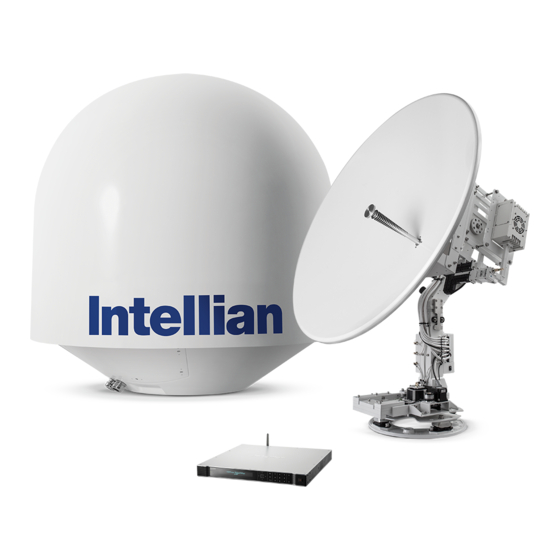
– Marine Satellite Communication System System Package The package of the Intellian v130G consists of antenna unit, ACU and installation kit box. Antenna unit Installation kit box... - Page 15 INSTALLING THE ANTENNA Antenna Unit The antenna unit includes an antenna pedestal inside a radome assembly. The pedestal consists of a satellite antenna main dish with RF components mounted on a stabilized pedestal. The radome protects the antenna pedestal assembly from the marine environment.
- Page 16 – Marine Satellite Communication System ACU (Antenna Control Unit) ACU provides power to the antenna and Block Up Converter (BUC), The digital Vacuum Fluorescent Display (VFD) allows for easy operation of the ACU, even in the dark. Antenna Control Unit...
-
Page 17: Installation Kit
INSTALLING THE ANTENNA Installation Kit Contains the items required for installing the antenna unit and ACU on the vessel. ACU box Description Q'ty Size Remarks Antenna Control Unit (ACU) 43.1 x 38 x 4.4cm Antenna Control Unit User Manual RF Hazard Sticker Radiation Safety Distance Label Mounting Template Wi-Fi Antenna... -
Page 18: Planning The Installation
– Marine Satellite Communication System Planning the Installation Selection of Antenna Installation Site Install the antenna in accordance with the following procedures to ensure maximum performance of the antenna. The ideal antenna site has a clear view of the horizon or satellite will all around clearance. -
Page 19: Configure Radiation Hazard/Blockage Zones
INSTALLING THE ACU Configure Radiation Hazard/Blockage Zones It is important to setup the radiation hazard or blockage zones for Intellian VSAT communication systems. The ACU can be programmed with relative azimuth and elevation sectors to create up to five zones where transmit power could endanger personnel who are frequently in that area or blockage exists. -
Page 20: Power Requirement
• Gyro Compass GPS Interface Cable (Customer Supplied) Type Multi-conductor, Shielded Number of cores 2 conductors for NMEA 0183, 5 conductors for NMEA 2000 Power Requirement Intellian v130G has been designed to work on a vessel’s power supply rated at 100- 240 V AC. -
Page 21: Tools Required For Installation
INSTALLING THE ANTENNA Tools Required for Installation 11 mm Spanner / Torque Wrench Power Drill 19 mm Spanner / Torque Wrench Phillips-Head Screwdriver 5 mm Allen/Hex key Flat Head Screwdriver (min 5mm) -
Page 22: Antenna Installation
– Marine Satellite Communication System Antenna Installation Unpacking the wooden crate of v130G Step 1. When uncrating the wooden crate, follow the procedures below. 1. Locate one of the side panels designed for fork lift. Detach this side panel by removing the fixing screw (1EA) and clips (8EA). - Page 23 INSTALLING THE ANTENNA Step 2. Remove 8 screws that mount the ACU box and installation kit box to the pallet.
- Page 24 – Marine Satellite Communication System Step 3. Lift the pallet using suitable lifting equipment to ensure safety of the workplace. Using a 19mm wrench remove the 4 shipping bolts that mount the antenna to the pallet. WARNING: When lifting the antenna by using the lifting strap, ensure to disassemble...
- Page 25 INSTALLING THE ANTENNA Step 4. Open the radome hatch. Flat Head Screwdriver (min 5mm) Radome Hatch...
- Page 26 – Marine Satellite Communication System Step 5. Remove the shipping brackets securing the AZ, EL and CL axis. Using your hand, gently check that the antenna moves freely in azimuth, elevation, and cross level without hitting any part of the radome's interior.
-
Page 27: Antenna Dimensions
INSTALLING THE ANTENNA Antenna Dimensions The method of installation and mounting of antenna may vary with vessel design but the following procedures are applicable in most situations, and will result in a secure and effective installation. Confirm the height and diameter of the antenna before installing it. -
Page 28: Antenna Mounting Templates
– Marine Satellite Communication System Antenna Mounting Templates The mounting holes must be in the exact same place as shown in the diagram below. The radome should be positioned with the Bow marker aligned as close as possible to the centerline of the ship. Variation from actual alignment can be compensated with the "BOW Adjust"... - Page 29 INSTALLING THE ANTENNA Position the Radome The radome should be positioned with the BOW marker aligned as closely as possible to the ship’s centerline. Recommended size of the support pedestal Mounting plate Min. 1cm(0.4”) Max. 3cm(1.2”) Min 60cm(24”) Support pedestal Max 150cm(60”) Appr.
- Page 30 Bolt the radome base directly to the support pedestal. Note: Ensure to use the Intellian supplied bolts from the accessory box when you mount the radome. Place each M12 nut on the bolt. Tighten each nut to 110 N.m (1,120 Kgf.cm) using a torque wrench and then tighten the outer nut a further 180 degree.
-
Page 31: Rf Cable Connections
INSTALLING THE ANTENNA RF Cable Connections Ensure that the switch on the power switch box is off during the installation period. When all the cables have been installed, turn on the switch. Compression collar Rubber Gland Power Switch Box LED Lamp Rotary TX Cable (From Antenna) ACU TX Cable... - Page 32 – Marine Satellite Communication System NOTE: Tightening torque Connector Type Tightening Torque F Type 1.0 N-m 0.6 N-m N Type 1.5 N-m Secure the RF Cables Using tie wraps and clips inside the radome, secure the RF cables connected to the power switch box.
-
Page 33: Installing The Acu
INSTALLING THE ACU Mounting the ACU 19” Rack Mount Type Table Mount Type ACU Dimensions Selection of ACU Installation Site Ship Gyrocompass Connection Connecting a Ship’s Gyrocompass Connecting the System without a Ship’s Gyrocompass ACU Connector Guide PC to ACU Communication Setup Wi-Fi Connection... -
Page 34: Mounting The Acu
– Marine Satellite Communication System Mounting the ACU Intellian supplies two types of mounting methods (a) 19” Rack Mount Type and (b) Table Mount Type to mount your ACU. 19" Rack Mount Type 19” Rack Mount Type - The ACU should be installed using the two supplied rack mounting brackets which allow for a side 19”... -
Page 35: Acu Dimensions
INSTALLING THE ACU ACU Dimensions 47.5 cm (18.7") Dimension of ACU 45.5 cm (17.9") 43.1 cm (17") 4.4 cm (1.7") 46.6 cm (18.4") 48.5 cm (19.1") Selection of ACU Installation Site The ACU should be installed below deck, in a location that is: •... -
Page 36: Ship Gyrocompass Connection
Connecting a Ship’s Gyrocompass The ship’s gyrocompass provides true heading input to the antenna allowing the antenna to target and acquire the desired satellite. Intellian always recommends to connect a ship’s gyrocompass to the antenna using the gyrocompass interface on the ACU. If the ship’s gyrocompass output is other than NMEA 0183 or NMEA 2000, the purchase of an NMEA converter may be required. - Page 37 Connecting the System without a Ship’s Gyrocompass For a vessel where a ship’s gyrocompass is not installed or is difficult to connect, the Intellian Gyro-Free satellite search function will be automatically enabled to allow the antenna to lock onto the desired satellite without requiring an external heading input.
- Page 38 – Marine Satellite Communication System ACU Connector Guide • Console Port ACU Console Port D-Sub 9 pin Male connector D-Sub 9 pin Female Supplied Component Signal Signal GPS OUT - GPS OUT + MODEM_SIGNAL_IN MODEM_LOCK MODEM_CTRL2 MODEM_CTRL1 (TX MUTE)
- Page 39 INSTALLING THE ACU • NMEA 2000 Connector Pins Sockets Connector Threads Connector Threads Male Connector Female Connector Pin Signal Pin Signal Shield Shield NET-S, (power supply positive, +V) NET-S, (power supply positive, +V) NET-C, (power supply common, -V) NET-C, (power supply common, -V) NET-H, (CAN-H) NET-H, (CAN-H) NET-L, (CAN-L)
-
Page 40: Pc To Acu Communication Setup
1. Connect an Ethernet cable from a PC Ethernet port to the Management port Ethernet Port on the front of the ACU. 2. Network connection is established. 3. Use the following IP address to access Intellian Aptus or Aptus Web page. ® • 192.168.2.1 (Default) Connection through Rear Panel Ethernet Port This method requires separate IP configuration on a PC. - Page 41 INSTALLING THE ACU Serial/USB Connection Connection through Serial Port Serial Connection 1. Connect a 9-pin Serial cable from the PC INTERFACE connector on the ACU to the 9-pin serial port on your PC. 2. If there is not a 9-pin serial port on the PC, use a USB-Serial adapter. Connection through USB Port USB Connection There are two USB(USB-to-Serial) ports are available on the ACU.
-
Page 42: Setup Wi-Fi Connection
– Marine Satellite Communication System Wi-Fi Connection Setup Wi-Fi Connection • Setting up the ACU in order to access Wi-Fi • Setting up the PC (AP Mode) in order to access Wi-Fi • Aptus Web Confirmation Setting up the ACU in order to access Wi-Fi 1. - Page 43 INSTALLING THE ACU Setting up the PC in order to access Wi-Fi 1. Setting up my computer’s wireless IP address - Control Panel> Network and Sharing Center > Change Adapter Settings > Right click on the “Local Area Connection ”> Click Properties After selecting TCP/IPv4, click on the properties menu, then select "Obtain an IP address automatically."...
- Page 44 – Marine Satellite Communication System 3. Connect Wi-Fi in AP mode. After clicking on the Windows Wireless Connection icon, click on intellian-VSAT (Default). 4. Enter the Network Security Key. Key: intellian1234 (Default) 5. You can confirm the logo and version data by accessing http://192.168.1.223 Aptus Web v X.XX...
-
Page 45: Operating The Acu
OPERATING THE ACU OPERATING THE ACU Introduction Normal Mode Setup Mode Installation Settings Antenna Settings Manual Search Setup Antenna LNB pol Angle Search Parameters Setup Antenna Parameters Setup Block Zone Antenna Diagnostic Test Satellite Settings Load Satellite Edit Satellite Information Add Satellite Information Check NID System Settings... - Page 46 Please ensure that your Intellian system is ALWAYS powered ON upon leaving the dock. Failure to follow these instructions could result in damaging mechanical parts in the antenna and/or possibly void your warranty. Intellian strongly recommends to restrain the antenna pedestal properly while underway when power is removed from...
-
Page 47: Normal Mode
OPERATING THE ACU Normal Mode Startup With the system installed and power applied, the ACU screen will show the following sequence. Start up I N T E L L I A N T E C H N O L O G I E S I N C . 1. - Page 48 – Marine Satellite Communication System Monitoring Antenna Current Status When the ACU power is on, it displays the status of the antenna. The current status of the antenna is displayed as shown below. Current search status S E A R C H 1 1 3 8 .
- Page 49 OPERATING THE ACU Tracking & Heading N B D F : 1 2 4 7 0 0 0 B W : 1 0 0 0 S I G : 3 0 1 information 0 0 4 . 5 3 E 5 2 .
- Page 50 – Marine Satellite Communication System Upgrade U P G R A D E ? the system Y E S 9. Touch OK key to upgrade firmware. Refer to the error messages below if any errors occur. UPGRADE FIRMWARE - FIRMWARE FILE NOT FOUND: the system cannot find the FWP file.
-
Page 51: Setup Mode
OPERATING THE ACU Setup Mode Enter the SETUP mode simply follow the instructions below. Searching / Tracking mode T R A C K I N G 1 3 8 . 0 E T E L S T _ 1 8 S I G : 3 0 1 A Z : 2 9 2 . -
Page 52: Installation Settings
– Marine Satellite Communication System Installation Settings During the first time installation, it is required to configure the installation settings. Setup mode S E T U P M O D E ? Y E S 1. Press LEFT arrow key to move cursor to YES and press OK key to enter SETUP mode... - Page 53 OPERATING THE ACU Gyro search mode Setting of Heading Device Existence of Heading Data NMEA/ Ground Test Device NMEA2000 With Heading Data Search 1 Search 3 Search 3 Without Heading Data Search 1 Search 1 Search 3 GYRO TYPE* NO DEVICE NMEA / NMEA 2000 GROUND TEST Modem Type &...
- Page 54 – Marine Satellite Communication System Load L O A D ? Y E S 8. Press BACK key to load the current setting or abort and return to the main display. Loading settings L O A D I N G . . .
-
Page 55: Antenna Settings
OPERATING THE ACU Antenna Settings Manual Search Search for the desired satellite manually. Setup mode S E T U P M O D E ? Y E S 1. Press LEFT arrow key to move cursor to YES and press OK key to enter SETUP mode. Antenna menu + A N T E N N A + S A T E L L I T E... - Page 56 – Marine Satellite Communication System Setup Antenna LNB pol Angle Setup mode S E T U P M O D E ? Y E S 1. Press LEFT arrow key to move cursor to YES and press OK key to enter SETUP mode.
- Page 57 OPERATING THE ACU Search Parameters Setup mode S E T U P M O D E ? Y E S 1. Press LEFT arrow key to move cursor to YES and press OK key to enter SETUP mode. Antenna menu + A N T E N N A + S A T E L L I T E + S Y S T E M...
- Page 58 – Marine Satellite Communication System Search 1 (Gyro Free) Search Pattern 3° 2° 1° Target Satellite EL Position 0° -1° -2° -3° Revolution (AZ direction) Search 1 antenna motion Target EL Angle 0° Target EL Angle + 0.5° Target EL Angle 0°...
- Page 59 OPERATING THE ACU Setup Antenna Parameters These parameters should only be changed by an authorized service technician. Improper setting of these parameters will cause your system to perform improperly. Setup mode S E T U P M O D E ? Y E S 1.
- Page 60 – Marine Satellite Communication System Set detect & tracking NBD D E T E C T N B D T R A C K I N G N B D 0 4 0 0 2 0 6. Set DETECT NBD and TRACKING NBD when NBD (Narrow band detection) mode of TRACKING SIGNAL is chosen to be used (Range: 1-200).
- Page 61 OPERATING THE ACU Select operation process O P E R A T I O N S A V E 8. Set OPERATION. Press UP and DOWN arrow keys to select OPERATION items. OPERATION* SAVE IDLE ON / OFF REBOOT SAVE: save and execute the current settings. The antenna is balanced at factory.
- Page 62 – Marine Satellite Communication System Setup Block Zone Up to 5 blockage or radiation hazard zones can be programmed with relative azimuth and elevation sectors. Setup mode S E T U P M O D E ? Y E S 1.
- Page 63 OPERATING THE ACU Block zone 2 Z O N E 2 B L O C K O F F 5. ZONE 2 to ZONE 5 BLOCK setting is same as ZONE 1 BLOCK. Press OK key to set ZONE 2 BLOCK and set next parameter. Save S A V E ? Y E S...
- Page 64 – Marine Satellite Communication System Antenna Diagnostic Test Refer to the diagnosis codes for the test results. Setup mode S E T U P M O D E ? Y E S 1. Press LEFT arrow key to move cursor to YES and press OK key to enter SETUP mode.
-
Page 65: Diagnosis Code
OPERATING THE ACU Diagnosis Code: CODE 101: Data communication test between the antenna and the ACU CODE 102: Azimuth motor test CODE 103: Elevation motor test CODE 104: Cross-level motor test CODE 105: Azimuth encoder test CODE 106: Cross-level encoder test CODE 107: Rate sensor test CODE 108: Tilt sensor test CODE 109: The sensor box motor is tested. -
Page 66: Satellite Settings
– Marine Satellite Communication System Satellite Settings Load Satellite Setup mode S E T U P M O D E ? Y E S 1. Press LEFT arrow key to move cursor to YES and press OK key to enter SETUP mode. - Page 67 OPERATING THE ACU Edit Satellite Information Setup mode S E T U P M O D E ? Y E S 1. Press LEFT arrow key to move cursor to YES and press OK key to enter SETUP mode. Satellite menu + A N T E N N A + S A T E L L I T E + S Y S T E M...
- Page 68 – Marine Satellite Communication System DVB verifiy method D V B V E R I F Y S K E W O F F S E T D V B D E C O D E + 0 . 0 6.
- Page 69 OPERATING THE ACU Set DVB tracking D V B F R E Q . S Y M B O L N I D frequency 1 1 7 4 7 M H z 2 1 3 0 0 K S p s 0 X 0 0 A D 9.
- Page 70 – Marine Satellite Communication System Add Satellite Information Setup mode S E T U P M O D E ? Y E S 1. Press LEFT arrow key to move cursor to YES and press OK key to enter SETUP mode.
- Page 71 OPERATING THE ACU Set LNB local frequency S E L E C T L O C A L T R A C K I N G S I G N A L 1 0 0 0 0 M H z N B D 6.
- Page 72 – Marine Satellite Communication System Save S A V E ? Y E S 10. Press LEFT arrow key to move cursor to YES and press OK key to save and execute the current settings. Or press RIGHT arrow key to move cursor to NO and press OK key to abort and return to the main display.
-
Page 73: System Settings
OPERATING THE ACU System Settings Set LNB Local Oscillator Frequency Setup mode S E T U P M O D E ? Y E S 1. Press LEFT arrow key to move cursor to YES and press OK key to enter SETUP mode. System menu + A N T E N N A + S A T E L L I T E... -
Page 74: Set Location
– Marine Satellite Communication System Set Location Setup mode S E T U P M O D E ? Y E S 1. Press LEFT arrow key to move cursor to YES and press OK key to enter SETUP mode. - Page 75 OPERATING THE ACU Latitude & longitude L A T I T U D E L O N G I T U D E 3 7 . 0 0 N 1 2 6 . 5 0 E 5. Set the current LATITUDE and LONGITUDE Press LEFT and RIGHT arrow keys until the desired character is underscored (selected).
- Page 76 – Marine Satellite Communication System Set Modem Port Setup mode S E T U P M O D E ? Y E S 1. Press LEFT arrow key to move cursor to YES and press OK key to enter SETUP mode.
- Page 77 EF Data Cooperation to offer common management interface for Comtech EF Data's Roaming Oceanic Satellite Server (ROSS) and ACU. VACP: is the interface between the SatLink mobile VSAT IDU and the Intellian antenna controllers for Intellian mobile antennas. ELEKTRIKOM-AMIP: is the interface using extended OpenAmip including the console port (modem lock) between the electrikom ROAM-PC and the Intellian controller.
- Page 78 – Marine Satellite Communication System Use TX mute G P S O U T S E N T E N C E U S E T X M U T E G P G L L Y E S 6.
-
Page 79: System Management
OPERATING THE ACU System Management Setup mode S E T U P M O D E ? Y E S 1. Press LEFT arrow key to move cursor to YES and press OK key to enter SETUP mode. System menu + A N T E N N A + S A T E L L I T E + S Y S T E M... - Page 80 – Marine Satellite Communication System Setup mode S E T U P M O D E ? Y E S 1. Press LEFT arrow key to move cursor to YES and press OK key to enter SETUP mode. System menu...
-
Page 81: Antenna Control Software
OPERATING THE ACU ANTENNA CONTROL SOFTWARE Introduction to Aptus ® Requirements Software Installation PC to ACU Communication Setup Starting Aptus ® Establishing a data communication Toolbar Menus System Property Status Dashboard Work View Tabs Antenna - Basic Info. Antenna - Advanced Info. Satellite Graph View Monitor... -
Page 82: Introduction To Aptus
– Marine Satellite Communication System Introduction to Aptus ® Intellian’s Antenna PC Controller Software, Aptus is a next-generation graphically ® based antenna remote control software. The Aptus allows users to easily and ® conveniently set up the antenna by using a personal computer. -
Page 83: Software Installation
® computer/ laptop. The InstallShield Wizard will guide you through the program setup process. The installation routine provides an icon on the desktop. Click the icon to start the software. In addition, Intellian also provides patch files for software upgrade. - Page 84 – Marine Satellite Communication System PC to ACU Communication Setup Starting Aptus ® Double-click the Aptus desktop icon, then Communication Window appears ® to establish the data communication between your PC and the ACU. Select options of connection method to access your ACU either through the Serial Port...
- Page 85 Do not plug a USB to the ACU while TCP/IP communication is in use. Doing so will disable current PC Software Control because the USB connection has higher priority than TCP/IP connection. - The amount of data will increase rapidly if Network Communication is in use. Intellian recommends using Aptus Web.
-
Page 86: Auto Update
– Marine Satellite Communication System AutoUpdate Intellian Aptus ® checks and notifies the latest version when it is started to maintain up to date software version by AutoUpdate function. 1. When Aptus ® is started, it automatically checks the latest software version from the server and runs AutoUpdate if new version is available. -
Page 87: Toolbar Menus
ANTENNA CONTROL SOFTWARE Toolbar Menus The toolbar menus at the top of the screen display command buttons of the most commonly used functions of the Aptus . The toolbar menus consists of 4 main ® menus; Quick (for quick launch of functions), File (for file backup, restoring and loading), View and Connection. - Page 88 – Marine Satellite Communication System Load Config. : loads the antenna configuration file (file format: *.cfg). The configuration file includes the antenna control parameters which are pre-loaded at the factory and should only be changed by an authorized service technician.
- Page 89 • Spectrum: displays current spectrum graph and allows to set spectrum data view options. Help • Report: provides e-mail contact to Intellian technical support team to let the user report problems at any time. • Information: displays the information of current Aptus ®...
-
Page 90: System Property Status Dashboard
– Marine Satellite Communication System System Property Status Dashboard The property status dashboard on the left pane of the screen provides the antenna status, the availability of TX transmission, signal level, GPS and heading status, software information, product information and error status to be monitored quickly. - Page 91 ANTENNA CONTROL SOFTWARE - Search 3: Search 3 pattern will automatically be initiated when AGC(DVB mode is in use) or SIG/dB (NBD mode is in use) falls below the current tracking level threshold value. Once the desired signal is found and above the predefined tracking threshold, the ACU will enter to tracking mode.
- Page 92 – Marine Satellite Communication System Signal Level Shows “DVB” when DVB mode of tracking signal is in use and “NBD” when NBD mode of tracking signal is in use. The “Red” line indicates the signal “Detect Level Threshold” and the “Orange” line indicates the signal “Tracking Level Threshold”.
- Page 93 OPERATING THE ACU Diagnostic Error Report The square button next to the Diagnostic Error Report turns red when the system receives an error. Click the button to see a Diagnostic Report.
-
Page 94: Work View Tabs
– Marine Satellite Communication System Work View Tabs Aptus provides seven Work View Tabs (Satellite View, Antenna Basic View, ® Antenna Advanced View, Monitor View, Graph View, ACU System View, and An- tenna UI View) to manage the Antenna and the Satellite configuration. - Page 95 (Consolidated Skew Offset = satellite skew offset + mechanical skew offset). Due to each satellite has its own skew offset, Intellian recommends you check with your service provider or satellite operator to get the satellite skew offset value and input it in Satellite Work Tab rather than resetting the mechanical skew offset directly.
- Page 96 – Marine Satellite Communication System 2. Antenna – Advanced Info. This view provides information on the Tilt Sensor Bias, Conical Range, EL Adjust, Rate Sensor, Search Parameter and Block Zone. -Tilt Sensor Bias: This maintains the elevation and the cross level axes in order to keep the pedestal parallel to the horizon.
- Page 97 ANTENNA CONTROL SOFTWARE · Step 4. Press the “Restart” icon to restart the antenna. - Rate Sensor: is used to calibrate the DC voltage output from the three rate sen- sors (azimuth, elevation, and cross-level). These are used to sense antenna motion that corresponds to the ship’s motion (roll, pitch, and yaw) for stabilizing the ped- estal.
- Page 98 – Marine Satellite Communication System · Search Step: set increment step size. · Type 1 & Type 3 (Search 1 & 3) Range: set Search 1 & 3 search range. Search 3 is conducted in a two-axis pattern consisting of alternate movements in azimuth and elevation as it forms an expanding square.
- Page 99 ANTENNA CONTROL SOFTWARE 3. Satellite This view provides information on the Satellite’s Information, Tracking Common Information, DVB and NBD Tracking Transponder, LNB Local Frequency, and Sat- ellite Library. This view shows a graphic UI of the current satellite that the antenna is pointing at and the satellites that are located at a 180°...
- Page 100 - LNB Local Frequency: Displays or sets LNB local frequency and its corre- sponding LNB voltage supplied. You may select pre-programmed LNB LO settings from the drop down list. This procedure is same for both the Intellian Global VSAT PLL LNB and any other LNB.
- Page 101 ANTENNA CONTROL SOFTWARE 4. Graph View This view provides information on Signal, Elevation (EL), Absolute AZ (Azimuth), Relative AZ, Heading, AZ and EL in Single or Multi graph formats. - Select Graph Item: shows the graphs of only the checked item(s) in a Single or Multi Graph View.
- Page 102 – Marine Satellite Communication System 5. Monitor This view provides a UI which can monitor all data that has been received from the ACU. - Tracking: turns on or off the dish scan function. If the dish scan function is disabled, the antenna will stop adjusting the antenna pointing angle in order to optimize the receive signal level.
- Page 103 6. Diagnostic / Modem This view provides Antenna Diagnostic Testing and also provides functions to set up the interface between the ACU and the Intellian VSAT Mediator or the satellite modem. - Diagnostic : select to run a full diagnostic test or single diagnostic test.
- Page 104 · LNB/ NBD: tests the LNB and NBD (narrow band detector). · Sensor Box Limit: tests the sensor box motor . - Modem: sets the interface between the ACU and the Intellian Dual VSAT Mediator or the satellite modem. NOTE: Before setting this function, make sure connection of a RJ45 cable from the Ethernet connector on the ACU to the modem or conect a 9 pin serial cable from the RS232/422 connector on the ACU to the modem.
- Page 105 ANTENNA CONTROL SOFTWARE · Use Modem Lock: selects whether or not to use external lock signal from the modem. “Use Modem Lock” will only be activated when the modem protocol is set as I/O Console. · TX Mute: TX Mute is a transmit inhibit output from the ACU to dis able /mute the modem transmit through a 5 V (HIGH) or 0 V (LOW) current whenever the antenna is blocked, searching, or is mis- pointed 0.5 degrees from peak satellite position.
- Page 106 – Marine Satellite Communication System 8. Work View Functions The seven Work View Tabs displayed in the Work View can be arranged in cus- tomized layouts. - Layout Formatting · Each of the Work View Tab can be separated from the rest Tabs.
- Page 107 ANTENNA CONTROL SOFTWARE Move the selected Work View Tab to the bottom position of the Work View layout. Move the selected Work View Tab to the right position of the Work View layout. Move the selected Work View Tab to the left position of the Work View layout.
- Page 108 – Marine Satellite Communication System You can also drag multiple Work View Tabs into a customized layout in the same manner. Click and hold left mouse button on each Work View Tab’s header and drag it onto a desired arrow on the Navigator icon. Then each Work View Tab can be placed to the desired positions as shown in the figure below.
- Page 109 ANTENNA CONTROL SOFTWARE Fit Work View Button: fits the current view to the Work View window size. The but- ton toggles between the fit view and the previous view. Zoom In and Zoom Out Bar: zooms in and out to expand and reduce the View to the desired size.
- Page 110 – Marine Satellite Communication System...
-
Page 111: Aptus Web
Antenna Position & Parameters Tracking setting Modem Setting Diagnostic Library Setting Firmware & Configuration Antenna Firmware Upgrade Antenna Log Antenna Backup & Restore Administration Network Setting SNMP Setting User Management iARM Upgrade iARM Save & Reboot Antenna Event Log Intellian Network Devices... - Page 112 – Marine Satellite Communication System Introduction With embedded Aptus Web software, the v-Series can be monitored, controlled, and diagnosed remotely from anywhere, anytime through the TCP/IP protocol. This not only can save time but also save the cost generated from the hundreds of routine maintenance activities such as operating firmware upgrades, tracking parameters resets, and system diagnostic.
- Page 113 Monitor the ACU (Monitoring Only). 2. Log into the ACU by typing in User Name and Password information. If this system has not been changed from the factory default: • User Name: intellian • Password: 12345678 v130 WARNING: The Control & Monitoring Mode will be switched to the Monitoring Only Mode in the following cases;...
- Page 114 – Marine Satellite Communication System Top Menus Once you log in, the following information and menus are displayed. Item Description Signal Level Display current signal level. - Setup: Displays whether or not the antenna is in SETUP mode. The indicator shows “Blue” in the SETUP mode.
- Page 115 APTUS WEB Dash Board & Information On the left side of the page, Dash Board and Information menus are displayed as below to provide quick monitoring of the antenna status and settings. Other menus are displayed only in the Control & Monitoring mode and their functions will be described in the next sections.
- Page 116 – Marine Satellite Communication System BOW Offset Display current bow offset Displays DVB tracking mode’s current tracking information. - Frequency: displays tracking frequency. - Symbol rate: displays symbol rate. DVB Information - NID: displays network ID. - Verify type: displays verification typ (AGC, DVB, DVB Decode) Displays NBD tracking mode’s current tracking information.
-
Page 117: Ship Setting
APTUS WEB Antenna Settings Ship Setting Item Description Ship Setting Set the ship information and block zone. Set GPS information. - Longitude (East/West) - Latitude (North/South) Bow Offset Set Bow Offset if needed. Set ship’s heading device (NONE, NMEA, NMEA2000, Heading Device Ground Test) and ship’s heading information Set the antenna’s block zones up to 5 by azimuth and eleva-... -
Page 118: Antenna Setting
– Marine Satellite Communication System Antenna Position & Parameters Item Description Set current antenna position and Search and Tracking parameters. These parameters should only be changed by Antenna Setting an authorized service technician. Improper setting of these parameters will render your system inoperable. - Page 119 APTUS WEB Item Description Release the elevation and cross level motor brakes while Idle Mode the antenna is in SETUP mode. The antenna can be moved manually during the mode. Reboot Reboot the system. DVB Detect and Tracking Level Threshold: display / set current detect level threshold and tracking level threshold when DVB tracking mode is chosen to be used.
-
Page 120: Tracking Setting
– Marine Satellite Communication System Tracking Setting Item Description Display or set current tracking mode and tracking Tracking Setting frequency of the target satellite. Display and set LNB’s local frequencies. Display Local Frequency Setting current LNB local frequency which is in use and (MHz) voltage. -
Page 121: Modem Setting
Set the modem interface. - Use Mediator: enable the usage of Mediator if the antenna is connected to the Intellian Dual VSAT Mediator. Use Mediator must be set to “NO” if there is no MEDIATOR connected to the ACU. Improper setting of this parameter will cause your ACU’s modem interface to work incorrectly. - Page 122 – Marine Satellite Communication System WARNING: Ensure to tick the checkbox before modifying the settings. Select ‘Set Modem Configuration’ to confirm the modem settings configured. Diagnostic Item Description Diagnostic Execute antenna diagnostic test. Select to run a full diagnostic test or single diagnostic test.
- Page 123 APTUS WEB Select to view a current spectrum graph and to set the Spectrum spectrum display options. Displays iDirect Modem status and control connection. This menu appears only when IDIRECT-AMIP protocol is selected at Modem Setting page. - Connection: control modem connection. - Modem IP: iDirect modem IP - Port: Connection ID for telnet - Password: Connection password for telnet...
-
Page 124: Library Setting
Display and set the satellite library information. - Get Library from ACU: Obtain satellite information installed in the ACU. - Open Library from PC: open the satellite library file from the supplied Intellian CD or from the external hard drive/PC. Library (File format: *.ilf) - Upload Library to ACU: upload the satellite library file to ACU. -
Page 125: Firmware & Configuration
APTUS WEB Firmware & Configuration Antenna Firmware Upgrade Item Description Antenna Firmware Upgrade antenna and ACU firmware version. Upgrade New Antenna Browse and select the firmware package file to upload and Firmware click Start Upload button. Current Running Display current firmware version (Antenna STABILIZER, Version Antenna PCU, ACU main, Library) Display Previous/Latest Package version and rollback... - Page 126 – Marine Satellite Communication System Upgrade procedures: 1. Select the upgrade package file. 2. Click on “Start Upload” button to transfer the Firmware package file (“*.fwp”) to iARM module. 3. After the package file is transferred, it’ll show “upgrade from vx.xx Version to vx.xx Version”.
- Page 127 APTUS WEB Firmware upgrade status page 5. It'll display information about the upgrade process status on full screen. Upgrade process status page 6. If the firmware is successfully upgraded, it'll display "The firmware update is completed." 7. Click on "Back to main page" to go out of the screen. To verify the upgraded firmware version, go to Dash Board >...
- Page 128 – Marine Satellite Communication System Upgrade complete page NOTE: To roll back to the previous firmware package version or latest package version, select Rollback Upgrade menu on the Antenna Firmware Upgrade page.
-
Page 129: Antenna Log
APTUS WEB Antenna Log Item Description Antenna Log Displays antenna log data GPS Log Option Disable/Enable to save GPS information in the antenna log file. Antenna Log Download the log file. Select start download button to proceed. Download Start Download Download the antenna log information. - Page 130 GPS information to third parties. Any issues regarding safety and privacy when turning on the GPS function is solely up to the user. Intellian is not responsible for information that is disclosed when the GPS function is enabled.
- Page 131 APTUS WEB Antenna Backup & Restore Item Description Enter Backup & Restore page. (Setup mode is Antenna Backup & Restore required) Backup antenna information to ACU/PC or Target restore antenna by using the saved information from ACU/PC. Backup Backup antenna information. Restore Restore antenna information.
-
Page 132: Network Setting
– Marine Satellite Communication System Administration Network Setting Item Description Network Setting Enter network setting page. Modify ACU’s Internal IP address and press Submit button. Go to “Save & Reboot” page and press Save & Reboot button to validate the changes. - Page 133 Sys Log Configuration - UDP Port : Management port - Message Type : Select message type (Intellian message level) to send to management server (Lower number indicates higher emergency). - Sys log Target Level : If you select this target level, the management server receives log message equal to or less than this level.
-
Page 134: Snmp Setting
– Marine Satellite Communication System SNMP Setting Item Description SNMP Setting Display and Set SNMP configuration. Set SNMP mode(Use Attribution Disable, Read Only SNMP V1/V2 Status or Read Write). V1/V2 Community Name Set SNMP V2 community name. V3 Authentication Type Set SNMP V3 authentication mode. -
Page 135: User Management
APTUS WEB User Management Item Description Change login ID and Password to access the Aptus Web. User Management This setting can be also accessed by ‘Account’ icon on the top menu. Change your login ID (user name) and password. - Change ID : Enter your current login ID (user name) and new login ID. -
Page 136: Iarm Upgrade
– Marine Satellite Communication System iARM Upgrade Item Description iARM Upgrade Upgrade the firmware of iARM module. Check New Check new iARM firmware available on the server. iARM Firmware Bootstrap Displays current bootstrap and bootloader version. /Bootloader ACU has 3 storage parts sys0, sys1, Factory Default. -
Page 137: Firmware Upload In Progress
APTUS WEB Firmware upload in progress 4. Do not turn off the ACU power if the firmware upgrade page is displayed. Firmware upgrade in progress 5. It’ll take around 2 minutes to complete the firmware upgrade. Once the upgrade is completed, the system will reboot automatically. -
Page 138: Iarm Save & Reboot
– Marine Satellite Communication System iARM Save & Reboot Item Description iARM Save settings to the ACU and reboot or reboot the system Save & Reboot without saving. Save the modified settings and reboot the system. Save & Reboot Click Save &... -
Page 139: Antenna Event Log
APTUS WEB Antenna Event Log Item Description Antenna Event Log Displays user's log information (Data/Time, Login ID and IP) Set the Log message option. - Severity : Set urgency level. - Category : Set target that caused the message. Query Filter - Time Frame : Set time limit that you want to show. - Page 140 • Eth1 IP Configuration : ACU network Eth1 IP and subnet Configuration mask setting. • Intellian Network Port Status : not used on t-series. Add Intellian network devices, then you can browse the various information of the device. Add Network Device •...
- Page 141 Appendix Appendix : Java Download and Install Guide NOTE: To run Java applications you must have Java Runtime Environment (JRE) version 6.0 and above installed in your PC/laptop. If JRE has not been installed in your PC/laptop, you’ll get the below message box. Click Run button to install it through online or offline download and install methods.
- Page 142 – Marine Satellite Communication System NOTE: The JRE installation guide may vary depending on the operating system installed in your PC/laptop. Method 1. Online method for downloading and installing http://www.java.com/en/download/manual.jsp...
- Page 143 Appendix Method 2. Offline method for downloading and installing http://www.java.com/en/download/help/windows_offline_download.xml This process requires you to download an executable file that includes all the files needed for the complete installation. You do not need to remain connected to the Internet during the installation. The file can also be copied to a computer that is not connected to the Internet.
- Page 144 – Marine Satellite Communication System 8. A few brief dialogs confirm the last steps of the installation process: click Close button on the last dialog. 9. This will complete Java installation process. NOTE: You may need to restart (close and re-open) your browser to enable the java...
-
Page 145: Technical Specification
Technical Specification General Approvals CE – conforms to EU Directive 89/336/EEC FCC – verified to CFR47: Part 15 Dimensions 165.2 x 168.9 cm Satellite Antenna Unit (65” x 66.5”) Antenna Dish Diameter 125 cm (49.2”) Antenna Control Unit 43.1 x 38.1 x 4.4 cm (17” x 15” x 1.7”) Weight Satellite Antenna Unit 146.8 kg (323 lbs) -
Page 146: Environment Specification
– Marine Satellite Communication System Environment Specification Specification Intellian Standards Relative Humidity = Max. 55% 1. Temperature -40°C to 80°C Humidity => 95% 2. Damp Heat 25°C to 55°C 1. DNV Resonance Search (X, Y, Z axis) - 2 to 13.2Hz : Displacement 3mm - 13.2 to 50Hz : Acceleration 2.1g... -
Page 147: Warranty
Technical Specification Warranty This product is warranted by Intellian Technologies Inc., to be free from defects in materials and workmanship for a period of THREE (3) YEARS on parts and TWO (2) YEARS on labor performed at Intellian Technologies, Inc. service center from the purchased date of the product.
Need help?
Do you have a question about the v130G and is the answer not in the manual?
Questions and answers