Table of Contents
Advertisement
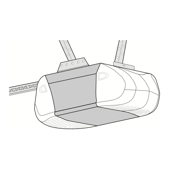
GARAGE DOOR OPENER
Models • 2265
1/2 HP
For Residential Use Only
Owner's Manual
Please read this manual and the enclosed safety materials carefully!
Fasten the manual near the garage door after installation.
The door WILL NOT CLOSE unless the Protector System
properly aligned.
Periodic checks of the opener are required to ensure safe operation.
The model number label is located on the front panel of your opener.
The Chamberlain Group, Inc.
845 Larch Avenue
Elmhurst, Illinois 60126-1196
www.chamberlaingroup.com
®
is connected and
®
Advertisement
Table of Contents

Related Manuals for Chamberlain 2265


Summary of Contents for Chamberlain 2265
- Page 1 GARAGE DOOR OPENER Models • 2265 1/2 HP For Residential Use Only Owner’s Manual Please read this manual and the enclosed safety materials carefully! Fasten the manual near the garage door after installation. The door WILL NOT CLOSE unless the Protector System properly aligned.
-
Page 2: Table Of Contents
Safety Symbol and Signal Word Review This garage door opener has been designed and tested to offer safe service provided it is installed, operated, maintained and tested in strict accordance with the instructions and warnings contained in this manual. WARNING... -
Page 3: Preparing Your Garage Door
To prevent damage to garage door and opener: • ALWAYS disable locks before installing and operating the opener. • ONLY operate garage door opener at 120V, 60 Hz to avoid malfunction and damage. Tools needed During assembly, installation and adjustment of the opener, instructions will call for hand tools as illustrated below. -
Page 4: Planning
Planning Identify the type and height of your garage door. Survey your garage area to see if any of the conditions below apply to your installation. Additional materials may be required. You may find it helpful to refer back to this page and the accompanying illustrations as you proceed with the installation of your opener. -
Page 5: Carton Inventory
Carton Inventory Your garage door opener is packaged in two cartons which contain the motor unit and all parts illustrated below. Accessories will depend on the model Multi-Function Door Control Panel Light Lens (2) 2 Conductor Bell Wire White & White/Red... -
Page 6: Assembly Step
ASSEMBLY STEP 1 Attach the T-Rail to the Motor Unit To avoid installation difficulties, do not run the garage door opener until instructed to do so. • Remove the two washered bolts mounted in top of motor unit. • Position T-rail at a 45˚ angle to opener so one hole in T-rail and motor unit line up. -
Page 7: Installation Safety Instructions
4. Disable all locks and remove all ropes connected to garage door before installing opener to avoid entanglement. 5. Install garage door opener 7 feet or more above floor. 6. Mount emergency release handle 6 feet above floor. 7. NEVER connect garage door opener to power source until instructed to do so. -
Page 8: Installation Step
INSTALLATION STEP 1 Determine the Header Bracket Location WARNING To prevent possible SERIOUS INJURY or DEATH: • Header bracket MUST be RIGIDLY fastened to CAUTION structural support on header wall or ceiling, otherwise garage door might not reverse when required. DO NOT install header bracket over drywall. - Page 9 ONE-PIECE DOOR WITHOUT TRACK 1. Close the door and mark the inside vertical centerline of your garage door. Extend the line onto the header wall above door, as shown. If headroom clearance is minimal, you can install the header bracket on the ceiling. See page 10. If you need to install the header bracket on a 2x4 (on wall or ceiling), use lag screws (not provided) to securely fasten the 2x4 to structural supports...
-
Page 10: Install The Header Bracket
INSTALLATION STEP 2 Install the Header Bracket You can attach the header bracket either to the wall above the garage door, or to the ceiling. Follow the instructions which will work best for your particular requirements. Do not install the header bracket over drywall. -
Page 11: Attach The T-Rail To The Header Bracket
Header Wall Header Bracket Chain Pulley Bracket T-rail Garage Door HARDWARE SHOWN ACTUAL SIZE Clevis Pin 5/16"x2-3/4" INSTALLATION STEP 3 Attach the T-Rail to the Header Bracket • Position the opener on the garage floor below the header bracket. Use packing material as a protective base. -
Page 12: Position The Opener
INSTALLATION STEP 4 Position the Opener Follow instructions which apply to your door type as illustrated. SECTIONAL DOOR OR ONE-PIECE DOOR WITH TRACK A 2x4 laid flat is convenient for setting an ideal door- to-rail distance. • Raise the opener onto a stepladder. You will need help at this point if the ladder is not tall enough. -
Page 13: Hang The Opener
Lag Screw 5/16"-18x1-7/8" Hex Bolt 5/16"-18x7/8" Nut 5/16"-18 To avoid possible SERIOUS INJURY from a falling garage door opener, fasten it SECURELY to structural supports of the garage. Concrete anchors MUST be used if installing any brackets into masonry. Figure 1 Measure Distance 5/16"-18x7/8"... -
Page 14: Install The Door Control
CAUTION INSTALLATION STEP 6 Install the Door Control Locate door control within sight of the door at a minimum height of 5 feet where small children cannot reach, and away from moving parts of the door and door hardware.The installation surface must be smooth and flat. -
Page 15: Install The Light Bulbs
• Reverse the procedure to close the lens. • If the bulbs burn out prematurely due to vibration, replace with a Garage Door Opener bulb. NOTE: Use only standard light bulbs. The use of short neck or speciality light bulbs may overheat the endpanel or light socket. -
Page 16: Electrical Requirements
WARNING INSTALLATION STEP 9 Electrical Requirements CAUTION To avoid installation difficulties, do not run the opener at this time. To reduce the risk of electric shock, your garage door opener has a grounding type plug with a third grounding pin. This plug will only fit into a grounding type outlet. -
Page 17: Install The Protector System
INSTALLATION STEP 10 Install The Protector System The safety reversing sensor must be connected and aligned correctly before the garage door opener will move in the down direction. IMPORTANT INFORMATION ABOUT THE SAFETY REVERSING SENSOR When properly connected and aligned, the sensor will detect an obstacle in the path of its electronic beam. - Page 18 INSTALLING THE BRACKETS Be sure power to the opener is disconnected. Install and align the brackets so the sensors will face each other across the garage door, with the beam no higher than 6" above the floor. They may be installed in one of three ways, as follows.
-
Page 19: Mounting And Wiring The Safety Sensors
MOUNTING AND WIRING THE SAFETY SENSORS • Slide a 1/4"-20x1/2" carriage bolt head into the slot on each sensor. Use wing nuts to fasten sensors to brackets, with lenses pointing toward each other across the door. Be sure the lens is not obstructed by a bracket extension. -
Page 20: Fasten The Door Bracket
INSTALLATION STEP 11 Fasten the Door Bracket Follow instructions which apply to your door type as illustrated below or on the following page. A horizontal reinforcement brace should be long enough to be secured to two or three vertical supports. A vertical reinforcement brace should cover the height of the top panel. -
Page 21: One-Piece Doors
ONE-PIECE DOORS Please read and comply with the warnings and reinforcement instructions on the previous page. They apply to one-piece doors also. • Center the door bracket on the top of the door, in line with the header bracket as shown. Mark either the left and right, or the top and bottom holes. -
Page 22: Connect Door Arm To Trolley
INSTALLATION STEP 12 Connect Door Arm to Trolley Follow instructions which apply to your door type as illustrated below and on the following page. SECTIONAL DOORS ONLY • Make sure garage door is fully closed. Pull the emergency release handle to disconnect the outer trolley from the inner trolley. -
Page 23: All One-Piece Doors
ALL ONE-PIECE DOORS 1. Assemble the door arm: • Fasten the straight and curved door arm sections together to the longest possible length (with a 2 or 3 hole overlap). • With the door closed, connect the straight door arm section to the door bracket with the 5/16"x1-1/4"... -
Page 24: Adjustment Pages
ADJUSTMENT STEP 1 Adjust the UP and DOWN Travel Limits Limit adjustment settings regulate the points at which the door will stop when moving up or down. To operate the opener, press the Door Control push bar. Run the opener through a complete travel cycle. •... -
Page 25: Adjust The Force
ADJUSTMENT STEP 2 Adjust the Force Force adjustment controls are located on the back panel of the motor unit. Force adjustment settings regulate the amount of power required to open and close the door. If the forces are set too light, door travel may be interrupted by nuisance reversals in the down direction and stops in the up direction. -
Page 26: Adjustment
The door will not move more than an inch, and the opener lights will flash. The garage door opener will not close from a remote if the indicator light in either sensor is off (alerting you to the fact that the sensor is misaligned or obstructed). -
Page 27: Operation Pages
• The wall-mounted Door Control: Hold the push button or bar down until the door starts to move. • The Keyless Entry (See Accessories): If supplied with your garage door opener, it must be programmed before use. See Programming. When the opener is activated (with the safety reversing sensor correctly installed and aligned) 1. -
Page 28: Using The Wall-Mounted Door Control
Using the Wall-Mounted Door Control THE MULTI-FUNCTION DOOR CONTROL Press the push bar to open or close the door. Press again to reverse the door during the closing cycle or to stop the door while it's opening. Light feature Press the Light button to turn the opener light on or off. -
Page 29: Care Of Your Garage Door Opener
CARE OF YOUR OPENER LIMIT AND FORCE ADJUSTMENTS: Weather conditions may cause some minor changes in door operation requiring some re- adjustments, particularly during the first year of operation. Pages 24 and 25 refer to the limit and force adjustments. Only a screwdriver is required. -
Page 30: Having A Problem
Installation Step 10. 12. The opener lights don't turn on: • Replace the light bulbs (100 watts maximum). Use a standard neck garage door opener bulb if regular bulb burns out. 13. The opener lights don't turn off: • Is the Light feature on? Turn it off. -
Page 31: Programming Pages
PROGRAMMING Your garage door opener has already been programmed at the factory to operate with your hand-held remote control. The door will open and close when you press the large push button. Below are instructions for programming your opener to operate with additional Security✚ remote controls. -
Page 32: To Add Or Change A Keyless Entry Pin
To Add or Change a Keyless Entry PIN Note: Your new Keyless Entry must be programmed to operate your garage door opener. USING THE “LEARN” BUTTON 1. Press and release the “learn” button on motor unit. The learn indicator light will glow steadily for 30 seconds. -
Page 33: Repair Parts Pages
REPAIR PARTS Rail Assembly Parts Installation Parts KEY PART 41A5273-1 41A5056-3 10A20 29B137 41A2828 217A238 41A5047 41A4353 41A5034 178B34 178B35 41A5266-1 41A2770-6 114A2497 PART DESCRIPTION 4A1008 Master link kit 41A4813 Chain pulley bracket 41A3489 Complete trolley assembly 183B99 One-piece T-rail 41D3484 Full chain assembly 83A11-2... -
Page 34: Motor Unit Assembly Parts
Motor Unit Assembly Parts PART DESCRIPTION 31D380 Sprocket cover 41C4220A Gear and sprocket assembly Complete with: Spring washer, Thrust washer, Retaining ring, Bearing plate, Roll pins (2), Drive gear and worm gear, Helical gear w/retainer and grease 41A2817 Drive/worm gear kit w/grease, Roll pins (2) 41B4245 Line cord... -
Page 35: Accessories
SECURITY✚ Keyless Entry: 976LM Enables homeowner to operate garage door opener from outside by entering a password on a specially designed keyboard. Also can add a temporary password for visitors or service persons. This temporary... -
Page 36: Liftmaster Service Is On Call
LIFTMASTER GARAGE DOOR OPENER ONE-YEAR LIMITED WARRANTY The Chamberlain Group, Inc., (“Seller”) warrants, to the first retail purchaser of this product, for the residence in which this product is originally installed, that it will be free from any defect in materials and/or workmanship for a period of one year from the date of purchase.
Need help?
Do you have a question about the 2265 and is the answer not in the manual?
Questions and answers