Table of Contents
Advertisement
Safe Operation Practices • Set-Up • Operation • Maintenance • Service • Troubleshooting • Warranty
O
'
M
peratOr
s
anual
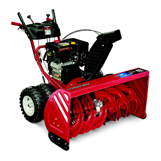
Two Stage Snow Thrower — Polar Blast 4510
WARNING
READ AND FOLLOW ALL SAFETY RULES AND INSTRUCTIONS IN THIS MANUAL
BEFORE ATTEMPTING TO OPERATE THIS MACHINE.
FAILURE TO COMPLY WITH THESE INSTRUCTIONS MAY RESULT IN PERSONAL INJURY.
TROY-BILT LLC, P.O. BOX 361131 CLEVELAND, OHIO 44136-0019
Printed In USA
FORM NO. 769-04060
(June 6, 2008)
Advertisement
Table of Contents

Related Manuals for Troy-Bilt 4510


Summary of Contents for Troy-Bilt 4510
- Page 1 Safe Operation Practices • Set-Up • Operation • Maintenance • Service • Troubleshooting • Warranty ’ peratOr anual Two Stage Snow Thrower — Polar Blast 4510 WARNING READ AND FOLLOW ALL SAFETY RULES AND INSTRUCTIONS IN THIS MANUAL BEFORE ATTEMPTING TO OPERATE THIS MACHINE.
-
Page 2: Table Of Contents
Call a Customer Support Representative at (800) 828-5500 or (330) 558-7220 ◊ Write us at Troy-Bilt LLC • P.O. Box 361131 • Cleveland, OH • 44136-0019 If you have any problems or questions concerning the machine, phone a authorized Troy-Bilt service dealer or contact us directly. -
Page 3: Important Safe Operation Practices
Important Safe Operation Practices WARNING! This symbol points out important safety instructions which, if not followed, could endanger the personal safety and/or property of yourself and others. Read and follow all instructions in this manual before attempting to operate this machine. Failure to comply with these instructions may result in personal injury. - Page 4 Safe Handling of Gasoline To avoid personal injury or property damage use extreme care in handling gasoline. Gasoline is extremely flammable and the vapors are explosive. Serious personal injury can occur when gasoline is spilled on yourself or your clothes which can ignite. Wash your skin and change clothes immediately.
- Page 5 Maintenance & Storage Never tamper with safety devices. Check their proper operation regularly. Refer to the maintenance and adjustment sections of this manual. Before cleaning, repairing, or inspecting machine disengage all control levers and stop the engine. Wait until the auger/impeller come to a complete stop. Disconnect the spark plug wire and ground against the engine to prevent unintended starting.
-
Page 6: Safety Symbols
Safety Symbols This page depicts and describes safety symbols that may appear on this product. Read, understand, and follow all instructions on the machine before attempting to assemble and operate. Symbol WARNING! Your Responsibility—Restrict the use of this power machine to persons who read, understand and follow the warnings and instructions in this manual and on the machine. -
Page 7: Assembly & Set-Up
Assembly & Set-Up Contents of Carton • One Snow Thrower • One Snow Thrower Operator’s Manual Assembly IMPORTANT: Two replacement auger shear pins are included with this manual (or stowed in the plastic handle panel). Refer to the Maintenance section for more information regarding shear pin replacement. - Page 8 NOTE: If the connector is not properly assembled, the shift rod will pivot and you will not be able to change speeds or direction. If the full range of speeds (forward and reverse) can not be achieved, refer to the “Maintenance and Adjustments” section. Chute Directional Control Remove the internal cotter pin from the upper chute crank.
- Page 9 Set-Up Shear Pins A pair of replacement auger shear pins and bow tie cotter pins have been included with your snow thrower. Store the pins in a convenient place for use if an original equipment shear pin should break. Chute Clean-Out Tool The chute clean-out tool is fastened to the top of the auger housing with a mounting clip and a cable tie at the factory.
- Page 10 With the auger control in the disengaged “up” position, walk to the front of the machine. Confirm that the auger has completely stopped rotating and shows NO signs of motion. If the auger shows ANY signs of rotating, immediately return to the operator’s position and shut off the engine.
-
Page 11: Controls And Features
Controls and Features Chute Assembly Augers Snow thrower controls and features are described below and illustrated in Fig. 4-1. NOTE: For detailed information on all engine controls, refer to the separate Briggs & Stratton Engine Operator’s Manual. Shift Lever The shift lever is located in the right side of the handle panel and is used to determine ground speed and direction of travel. -
Page 12: Auger Control
Primer Bulb Pressing the primer bulb forces fuel directly into the engine’s carburetor to aid in starting a “Cold” engine. NOTE: Do not use the primer bulb to restart a warm engine after a short shutdown. Oil Fill Engine oil level can be checked and oil added through the oil fill. Skid Shoes Position the skid shoes based on surface conditions. - Page 13 Two-Way Chute Control™ The two-way chute control is located on the left side of the dash panel and is used to control the distance of snow discharge from the chute. • To change the upper chute angle to control the distance that snow is thrown, pivot the lever forward or backward.
-
Page 14: Operation
Operation Starting The Engine Attach spark plug wire to spark plug. Make certain the metal loop on the end of the spark plug wire (inside the rubber boot) is fastened securely over the metal tip on the spark plug. Make certain both the auger control and drive control are in the disengaged (released) position. -
Page 15: Operating Tips
To Engage Drive Move the shift lever into one of the six forward (F) positions or two reverse (R) positions. Select a speed appropriate for the snow conditions and a pace you’re comfortable with. NOTE: Use slower speeds in higher snow and/or until you are familiar with the snow thrower operation. -
Page 16: Maintenance & Adjustment
Maintenance & Adjustments Maintenance Engine Refer to the Briggs & Stratton Engine manual packed with your machine for all engine maintenance. Shave Plate and Skid Shoes The shave plate and skid shoes on the bottom of the snow thrower are subject to wear. They should be checked periodically and replaced when necessary. - Page 17 Auger Shaft At least once a season, one at a time, remove the shear pins from the auger shaft. Spray lubricant inside the hub of each auger spiral assembly and around the spacers on the auger shaft. Grease fittings can also be found at each end of the auger shaft. Lubricate flange bearings found at each end of the shaft with a grease gun once a season.
- Page 18 Loosen the two nuts which secure the chute bracket and reposition it slightly. Refer to Figure 6-5. Retighten the nuts. Drive Control ” Refer to “Auger and Drive Control Cables of the Assembly & Set-Up - Section 3 for instructions to adjust the drive control. To further check the adjustment, proceed as follows: With the snow thrower tipped forward (be certain to drain gasoline or place plastic film under the gas cap if the snow...
-
Page 19: Service
Service Belt Replacement Belt Removal Preparation Disconnect the chute crank assembly at the discharge chute end by removing the hairpin clip and the flat washer. Refer to Figure 7-1. Figure 7-1 Remove the hex screws and lock nuts securing the forward end of the support tubes to the back of the auger housing, and pivot the tubes upward. - Page 20 Slip the auger control belt (the front belt) off the engine pulley. Pull the brake bracket assembly towards the cable guide roller and unhook the auger cable “Z” fitting. Refer to Figure 7-5. Figure 7-5 From both sides of the frame assembly, use a 1/2" wrench to remove the three hex tap screws securing the transmission frame to the auger housing assembly.
- Page 21 If also replacing the drive belt, proceed to the “Drive Belt” instruction. If not, reposition the transmission frame back onto the auger housing. Install the drive belt on the engine pulley, re-connect the auger cable “Z” fitting and auger idler rod ferrule to the brake bracket.
- Page 22 Holding the friction wheel assembly, slide the hex shaft out of the right side of the frame. The spacer on the left side of the hex shaft will fall and the sprocket should remain hanging lose in the chain. Lift the friction wheel assembly out between the axle shaft and the drive shaft assemblies.
- Page 23 Off-Season Storage If the snow thrower will not be used for 30 days or longer, the equipment needs to be stored properly. Follow storage instructions below to ensure top performance from the snow thrower for many more years. Refer to the engine manual for more detailed NOTE: information on preparing the snow thrower engine for storage.
-
Page 24: Troubleshooting
Troubleshooting Problem Engine fails to start Engine runs erratic Engine overheats Excessive vibration Loss of power Unit fails to propel itself Unit fails to discharge snow Cause Choke control not in ON position. Spark plug wire disconnected. Fuel tank empty or stale fuel. Engine not primed. -
Page 25: Replacement Parts
Replacement Parts Component Phone (800) 828-5500 to order replacement parts or a complete Parts Manual (have your full model number and serial number ready). Parts Manual downloads are also available free of charge at www.troybilt.com. Description Extention Cord, 110V Auger Drive Belt Wheel Drive Belt Friction Wheel Assembly Friction Wheel w/Bonded Rubber... - Page 26 Notes...
- Page 27 10 — n ectiOn Otes...
-
Page 28: Warranty
MANUFACTURER’S LIMITED WARRANTY FOR The limited warranty set forth below is given by Troy-Bilt LLC with respect to new merchandise purchased and used in the United States and/or its territories and possessions, and by MTD Products Limited with respect to new merchandise purchased and used in Canada and/or its territories and possessions (either entity respectively, “Troy-Bilt”).
Need help?
Do you have a question about the 4510 and is the answer not in the manual?
Questions and answers