Table of Contents
Advertisement
Quick Links
CONTENTS
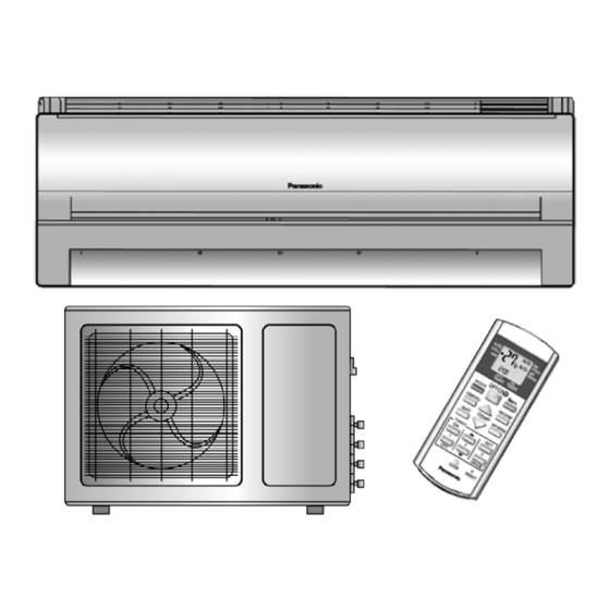
CS-C9DKZW CU-2C18DKH
CS-C9DKZW CU-3C20DKH
Page
2
3
6
6
8
10
10
11
12
13
15
17
© 2004 Panasonic HA Air-Conditioning (M) Sdn Bhd
(11969-T). All rights reserved. Unauthorized copying
and distribution is a violation of law.
Order No. MAC0501011C3
Air Conditioner
Page
17
18
19
20
23
25
25
26
26
27
28
Advertisement
Table of Contents

Related Manuals for Panasonic CS-C9DKZW


Summary of Contents for Panasonic CS-C9DKZW
-
Page 1: Table Of Contents
5 Refrigeration Cycle Diagram 8.9. Powerful Operation 6 Block Diagram 8.10. Quiet Operation 7 Wiring Diagram 8.11. Ionizer Operation 8 Operation Details © 2004 Panasonic HA Air-Conditioning (M) Sdn Bhd (11969-T). All rights reserved. Unauthorized copying and distribution is a violation of law. -
Page 2: Features
CS-C9DKZW CU-2C18DKH / CS-C9DKZW CU-3C20DKH 8.12. Timer Control 13.1. Refrigeration cycle system 8.13. Random Auto Restart Control 13.2. Relationship between the condition of the air conditioner 8.14. Remote Control Signal Receiving Sound and pressure and electric current 9 Operating Instructions 13.3. -
Page 3: Functions
CS-C9DKZW CU-2C18DKH / CS-C9DKZW CU-3C20DKH 2 Functions... - Page 4 CS-C9DKZW CU-2C18DKH / CS-C9DKZW CU-3C20DKH...
- Page 5 CS-C9DKZW CU-2C18DKH / CS-C9DKZW CU-3C20DKH Outdoor Unit CU-2C18DKH & CU-3C20DKH Compressor Reverse Rotation Protection Control • To protect compressor from reverse rotation when there is a instantaneous power failure. Overload Protector • 2-stage OLP to protect the compressor. Overload Protector will trip when –...
-
Page 6: Product Specifications
CS-C9DKZW CU-2C18DKH / CS-C9DKZW CU-3C20DKH 3 Product Specifications 3.1. CS-C9DKZW CU-2C18DKH Unit Indoor unit Outdoor unit Power Source (Phase, Voltage, Cycle) Single 240 - 220 ø, V, Hz Cooling Capacity (1 unit) 2.44 - 2.40 (2 units) 4.88 - 4.80... - Page 7 CS-C9DKZW CU-2C18DKH / CS-C9DKZW CU-3C20DKH Unit Indoor unit Outdoor unit Fan Motor Description Cross-flow Fan Propeller Fan Material AS + Glass Fiber 20% AS + Glass Fiber 20% Type Induction (4-poles) Induction (6-poles) Input 29.3 - 26.3 134.6 - 118.8...
-
Page 8: Cs-C9Dkzw Cu-3C20Dkh
CS-C9DKZW CU-2C18DKH / CS-C9DKZW CU-3C20DKH 3.2. CS-C9DKZW CU-3C20DKH Indoor unit Outdoor unit Unit Single Operation Single Operation Double Operation Triple Operation (A, B1, B2) (B1 or B2) (B1 + B2) (A + B1 or B2) (A + B1 + B2) - Page 9 CS-C9DKZW CU-2C18DKH / CS-C9DKZW CU-3C20DKH Indoor unit Outdoor unit Fan Motor Description Cross-flow Fan Propeller Fan Material AS + Glass Fiber AS + Glass Fiber 20% Type Induction (4-poles) Induction (6-poles) Input 29.3 - 26.3 134.0 - 118.7 Rated Output 750 - 750 —...
-
Page 10: Dimensions
CS-C9DKZW CU-2C18DKH / CS-C9DKZW CU-3C20DKH 4 Dimensions 4.1. Indoor Unit & Remote Control... -
Page 11: Outdoor Unit
CS-C9DKZW CU-2C18DKH / CS-C9DKZW CU-3C20DKH 4.2. Outdoor Unit... -
Page 12: Refrigeration Cycle Diagram
CS-C9DKZW CU-2C18DKH / CS-C9DKZW CU-3C20DKH 5 Refrigeration Cycle Diagram... -
Page 13: Block Diagram
CS-C9DKZW CU-2C18DKH / CS-C9DKZW CU-3C20DKH 6 Block Diagram... - Page 14 CS-C9DKZW CU-2C18DKH / CS-C9DKZW CU-3C20DKH...
-
Page 15: Wiring Diagram
CS-C9DKZW CU-2C18DKH / CS-C9DKZW CU-3C20DKH 7 Wiring Diagram... - Page 16 CS-C9DKZW CU-2C18DKH / CS-C9DKZW CU-3C20DKH...
-
Page 17: Operation Details
CS-C9DKZW CU-2C18DKH / CS-C9DKZW CU-3C20DKH 8 Operation Details 8.1. Cooling Operation • Cooling operation can be set using remote control. • This operation is applied to cool down the room temperature reaches the setting temperature set on the remote control. -
Page 18: Soft Dry Operation
CS-C9DKZW CU-2C18DKH / CS-C9DKZW CU-3C20DKH 8.2. Soft Dry Operation • Soft Dry operation can be set using remote control. • Soft Dry operation is applied to dehumidify and to perform a gentle cooling to the room. • This operation starts when the intake air temperature sensor reaches the setting temperature on the remote control. -
Page 19: Automatic Operation
CS-C9DKZW CU-2C18DKH / CS-C9DKZW CU-3C20DKH 8.3. Automatic Operation • Automatic operation can be set using remote control. • This operation starts to operate with indoor fan at SLo speed for 20 seconds to judge the intake air temperature. • After judged the temperature, the operation mode is determined by referring to the below standard. -
Page 20: Operation Control
CS-C9DKZW CU-2C18DKH / CS-C9DKZW CU-3C20DKH 8.4. Operation Control 8.4.1. Restart Control (Time Delay Safety Control) • When the thermo-off temperature (temperature which compressor stops to operate) is reached during:- − Cooling/Heating operation - the compressor stops for 3 minutes (minimum) before resume operation. - Page 21 CS-C9DKZW CU-2C18DKH / CS-C9DKZW CU-3C20DKH 8.4.5. Anti-Freezing Control • If the temperature of the indoor heat exchanger falls below 2°C continuously for 4 minutes or more, the compressor turns off. The fan speed setting remains the same. • This phenomenon is to protect the indoor heat exchanger from freezing and to prevent higher volume of refrigerant in liquid form returning to the compressor.
- Page 22 CS-C9DKZW CU-2C18DKH / CS-C9DKZW CU-3C20DKH • Anti-Dew Formation is control by: • Increasing Air Flow Volume 1. Lo fan speed Lo fan speed is changed to Lo+ after 30 min to prevent dew formation. 2. QLo fan speed Dew formation may occurs at QLo cool, therefore QLo cool is operated only 1 hr 30 min (1 hr QLo, 30 min QLo + 80 rpm).
-
Page 23: Indoor Fan Speed Control
CS-C9DKZW CU-2C18DKH / CS-C9DKZW CU-3C20DKH During Anti-dew condensation prevention, Airflow Direction Manual control angle change from 10°, 15°, 20°, 32° to 22°, 24°, 26°, 28°, 30°. 8.5. Indoor Fan Speed Control • Indoor Fan Speed can be set using remote control. - Page 24 CS-C9DKZW CU-2C18DKH / CS-C9DKZW CU-3C20DKH 8.5.2. Automatic Fan Speed Control • When set to Auto Fan Speed, the fan speed is adjusted between maximum and minimum setting as shown in the table. − Fan speed rotates in the range of Hi and Me.
-
Page 25: Outdoor Fan Speed Control
CS-C9DKZW CU-2C18DKH / CS-C9DKZW CU-3C20DKH Auto Fan Speed during Soft Dry operation: 1. Indoor fan will rotate alternately between off and Lo-. 2. At the beginning of each compressor start operation, indoor fan will increase fan speed gradually for deodorizing purpose. -
Page 26: Horizontal Airflow Direction Control
CS-C9DKZW CU-2C18DKH / CS-C9DKZW CU-3C20DKH 8.8. Horizontal Airflow Direction Control • The horizontal airflow direction louvers can be adjusted manually by hand. 8.9. Powerful Operation • The Powerful operation is to achieve the setting temperature quickly. • When Powerful operation is set, the setting temperature will be automatically decreased 3°C internally against the present setting temperature (Lower temperature limit: 16°C). -
Page 27: Quiet Operation
CS-C9DKZW CU-2C18DKH / CS-C9DKZW CU-3C20DKH 8.10. Quiet Operation (For Cooling Operation or cooling region of Soft Dry Operation) • The Quiet operation is to provide quiet/cooling operation condition compare to normal operation. • Once the Quiet Mode is set at the remote control, the Quiet Mode LED illuminated. The sound level will reduce around 2 dB(A) for Lo fan speed or 3 dB(A) for Hi/Me fan speed against the present operation sound level. -
Page 28: Ionizer Operation
CS-C9DKZW CU-2C18DKH / CS-C9DKZW CU-3C20DKH 8.11. Ionizer Operation • The Ionizer operation is to provide fresh air effect to user by producing minus ion in discharge air. 8.11.1. Operation Control 1. Ionizer individual operation a. When air-conditioner unit is at “OFF” condition (standby) and ION operation button at the remote control is pressed, the Ionizer operation will turn on. -
Page 29: Timer Control
CS-C9DKZW CU-2C18DKH / CS-C9DKZW CU-3C20DKH 8.11.2. Error Detection Control • The error detection control is to inform user that error occurs at ionizer system and repairing job will be needed. • There are two types of error detection control: a. When Ionizer is ON −... -
Page 30: Operating Instructions
CS-C9DKZW CU-2C18DKH / CS-C9DKZW CU-3C20DKH 9 Operating Instructions... - Page 31 CS-C9DKZW CU-2C18DKH / CS-C9DKZW CU-3C20DKH...
- Page 32 CS-C9DKZW CU-2C18DKH / CS-C9DKZW CU-3C20DKH...
- Page 33 CS-C9DKZW CU-2C18DKH / CS-C9DKZW CU-3C20DKH...
- Page 34 CS-C9DKZW CU-2C18DKH / CS-C9DKZW CU-3C20DKH...
- Page 35 CS-C9DKZW CU-2C18DKH / CS-C9DKZW CU-3C20DKH...
-
Page 36: Installation Instructions
CS-C9DKZW CU-2C18DKH / CS-C9DKZW CU-3C20DKH 10 Installation Instructions Required tools for Installation Works 1. Philips screw driver 5. Spanner 9. Gas leak detector 13. Multimeter 2. Level gauge 6. Pipe cutter 10. Measuring tape 14. Torque wrench 18 N.m (1.8 kgf.m) 42 N.m (4.2 kgf.m) - Page 37 CS-C9DKZW CU-2C18DKH / CS-C9DKZW CU-3C20DKH 1. The equipment must be earthed. It may cause electrical shock if grounding is not perfect. 2. Do not install the unit at place where leakage of flammable gas may occur. In case gas leaks and accumulates at surrounding of the unit, it may cause fire.
-
Page 38: Attached Accessories
CS-C9DKZW CU-2C18DKH / CS-C9DKZW CU-3C20DKH 10.2. Attached accessories 10.4. Indoor/Outdoor Unit Installation Diagram Applicable piping kit CZ-3F5, 7AEN (CS-C9DKZW) 10.3. Select the best location INDOOR UNIT • There should not be any heat source or steam near the unit. • There should not be any obstacles blocking the air circulation. -
Page 39: Indoor Unit
CS-C9DKZW CU-2C18DKH / CS-C9DKZW CU-3C20DKH 10.5. Indoor unit 10.5.1. SELECT THE BEST LOCATION 10.5.3. TO DRILL A HOLE IN THE WALL (Refer to “Select the best location” AND INSTALL A SLEEVE OF section) PIPING 1. Insert the piping sleeve to the hole. - Page 40 CS-C9DKZW CU-2C18DKH / CS-C9DKZW CU-3C20DKH 3. For the embedded piping (This can be used for left rear piping & left bottom piping also.)
- Page 41 CS-C9DKZW CU-2C18DKH / CS-C9DKZW CU-3C20DKH 10.5.5. CONNECT THE CABLE TO THE INDOOR UNIT 1. The inside and outside connecting cable can be connected without removing the front grille. 2. Connecting cable between indoor unit and outdoor unit shall be approved polychloroprene sheathed 4 × 1.5 mm flexible cord, type designation 245 IEC 57 or heavier cord.
- Page 42 CS-C9DKZW CU-2C18DKH / CS-C9DKZW CU-3C20DKH HOW TO TAKE OUT FRONT GRILLE AUTO SWITCH OPERATION Please follow the steps below to take out front grille if The below operations will be performed by pressing the necessary such as when servicing. “AUTO” switch.
-
Page 43: Outdoor Unit
CS-C9DKZW CU-2C18DKH / CS-C9DKZW CU-3C20DKH 10.6. Outdoor unit 10.6.1. SELECT THE BEST LOCATION (Refer to “Select the best location” section) 10.6.2. INSTALL THE OUTDOOR UNIT • After selecting the best location, start installation according to Indoor/Outdoor Unit Installation Diagram. 1. Fix the unit on concrete or rigid frame firmly and horizontally by bolt nut. - Page 44 CS-C9DKZW CU-2C18DKH / CS-C9DKZW CU-3C20DKH CUTTING AND FLARING THE PIPING 1. Please cut using pipe cutter and then remove the burrs. 2. Remove the burrs by using reamer. If burrs is not removed, gas leakage may be caused. Turn the piping end down to avoid the metal powder entering the pipe.
- Page 45 CS-C9DKZW CU-2C18DKH / CS-C9DKZW CU-3C20DKH 2) Air purging The air which contains remaining moisture in the refrigeration cycle may cause a malfunction on the compressor. 1. To purge the air, push the pin on the gas side 3-way valve for three seconds using with a hexagonal wrench and set it free for one minute.
- Page 46 CS-C9DKZW CU-2C18DKH / CS-C9DKZW CU-3C20DKH 10.6.6. PIPE INSULATION 1. Please carry out insulation at pipe connection portion as mentioned in Indoor/Outdoor Unit Installation Diagram. Please wrap the insulated piping end to prevent water from going inside the piping. 2. If drain hose or connecting piping is in the room (where dew may form), please increase the insulation by using POLY-E FOAM with thickness 6 mm or above.
-
Page 47: 11 3-Way Valve
CS-C9DKZW CU-2C18DKH / CS-C9DKZW CU-3C20DKH 11 3-way Valve 3-way Valve (Liquid Side) 3-way Valve (Gas Side) Works Shaft Position Service Port Shaft Position Service Port Shipping Closed Closed Closed Closed (With valve cap) (With cap) (With valve cap) (With cap) -
Page 48: Air Purging
CS-C9DKZW CU-2C18DKH / CS-C9DKZW CU-3C20DKH 11.1. Air purging The air in the indoor unit and in the piping must be purged. If air Required tools: Hexagonal wrench, adjustable wrench, remains in the refrigeration pipes, it will affect the compressor, torque wrenches, wrench to hold the reduce the cooling capacity, and could lead to a malfunction. -
Page 49: Pumping Down
CS-C9DKZW CU-2C18DKH / CS-C9DKZW CU-3C20DKH 11.2. Pumping down Procedure: 1. Confirm that both the 3-way valves are set to the open 6. Operate the air conditioner at the cooling cycle and position. stop it when the gauge indicates 0 kg/cm •... - Page 50 CS-C9DKZW CU-2C18DKH / CS-C9DKZW CU-3C20DKH 11.2.1. Re-air purging (Re-installation) Procedure: 1. Remove the cap nut from 3-way valves. 5. Check for gas leakage. • Remove the cap nut from 3-way valves after carefully • Check the flare connections for gas leakage.
- Page 51 CS-C9DKZW CU-2C18DKH / CS-C9DKZW CU-3C20DKH 11.2.2. Balance refrigerant of the 3-way valves (Gas leakage) Procedure: 1. Confirm that both the 3-way valves are set to the open position. 2. Connect the charge set to the Gas side 3-way valve’s port.
-
Page 52: Evacuation
CS-C9DKZW CU-2C18DKH / CS-C9DKZW CU-3C20DKH 11.3. Evacuation (No refrigerant in the refrigeration cycle) Procedure: 1. Connect the vacuum pump to the charge set’s centre hose. 2. Evacuation for approximately one hour. • Confirm that the gauge needle has moved toward -76 cmHg [vacuum of 4 mmHg or less]. -
Page 53: Gas Charging
CS-C9DKZW CU-2C18DKH / CS-C9DKZW CU-3C20DKH 11.4. Gas charging (After Evacuation) Procedure: 1. Connect the charge hose to the charging cylinder. 4. Immediately disconnect the charge hose from both the 3-way valve’s service ports. • Connect the charge hose which you disconnected from the vacuum pump to the valve at the bottom of the •... -
Page 54: Servicing Information
CS-C9DKZW CU-2C18DKH / CS-C9DKZW CU-3C20DKH 12 Servicing Information 12.1. Distinction of Lead Free (PbF) Printed Circuit Board Printed circuit boards (manufactured) using lead free solder will have a PbF stamp on the Printed Circuit board. CAUTION • Pb free solder has a higher melting point than standard solder; typically the melting point is 50 - 70°F (30 - 40°C) higher. -
Page 55: Indoor Fan Motor And Cross Flow Fan Removal Procedures
CS-C9DKZW CU-2C18DKH / CS-C9DKZW CU-3C20DKH − Release CN-TH connector (Fig. 4) − Release CN-STM connector (Fig. 4) − Release CN-REC/DISP connector (Fig. 4) Fig. 4 − To remove the electronic controller. − Remove the particular piece (Fig. 4) − Release CN-FM connector (Fig. 4) Fig. -
Page 56: Auto Off/On Button
CS-C9DKZW CU-2C18DKH / CS-C9DKZW CU-3C20DKH − Remove the earth wire from the evaporator (Fig. 7) − Remove the cross flow fan bushing from the chassis. (Fig. 9) − Release the generator complete wire (green and red). − Loosen the fan boss screw at the cross flow fan. (Fig. 9) (Fig. -
Page 57: Remote Control Reset
CS-C9DKZW CU-2C18DKH / CS-C9DKZW CU-3C20DKH 12.4.2. Remote Control Transmission Code • There are 4 type of remote control transmission code could be selected and stored in EEPROM of indoor unit. The indoor unit will only operate when received signal with same transmission code from remote control. This could prevent signal inteference when there are 2 or more indoor unit installed nearby together. -
Page 58: Troubleshooting Guide
CS-C9DKZW CU-2C18DKH / CS-C9DKZW CU-3C20DKH 13 Troubleshooting Guide 13.1. Refrigeration cycle system In order to diagnose malfunctions, make sure that there are no electrical problems before inspecting the refrigeration cycle. Such problems include insufficient insulation, problem with the power source, malfunction of a compressor and a fan. -
Page 59: Relationship Between The Condition Of The Air Conditioner And Pressure And Electric Current
CS-C9DKZW CU-2C18DKH / CS-C9DKZW CU-3C20DKH 13.2. Relationship between the condition of the air conditioner and pressure and electric current Cooling Mode Condition of the air conditioner Low Pressure High Pressure Electric current during operation Insufficient refrigerant (gas leakage) Clogged capillary tube or... -
Page 60: Technical Data
CS-C9DKZW CU-2C18DKH / CS-C9DKZW CU-3C20DKH 14 Technical Data 14.1. Thermostat characteristics 14.2. Operation characteristics 14.2.1. CS-C9DKZW CU-2C18DKH... - Page 61 CS-C9DKZW CU-2C18DKH / CS-C9DKZW CU-3C20DKH 14.2.2. CS-C9DKZW CU-3C20DKH...
-
Page 62: Exploded View (Indoor Unit)
CS-C9DKZW CU-2C18DKH / CS-C9DKZW CU-3C20DKH 15 Exploded View (Indoor Unit) Note: The above exploded view is for the purpose of parts disassembly and replacement. The non-numbered parts are not kept as standard service parts. -
Page 63: Replacement Parts List (Indoor Unit)
CS-C9DKZW CU-2C18DKH / CS-C9DKZW CU-3C20DKH 16 Replacement Parts List (Indoor Unit) 16.1. CS-C9DKZW REF. NO. PART NAME & DESCRIPTION QTY. CS-C9DKZW REMARKS CHASSY COMPLETE CWD50C1377 FAN MOTOR, AC 15W SINGLE CWA921181 CROSS FLOW FAN COMPLETE CWH02C1031 BEARING ASS’Y CWH64K007 SCREW - CROSS FLOW FAN... -
Page 64: Exploded View (Outdoor Unit)
CS-C9DKZW CU-2C18DKH / CS-C9DKZW CU-3C20DKH 17 Exploded View (Outdoor Unit) 17.1. CU-2C18DKH Note: The above exploded view is for the purpose of parts disassembly and replacement. The non-numbered parts are not kept as standard service parts. -
Page 65: Replacement Parts List (Outdoor Unit)
CS-C9DKZW CU-2C18DKH / CS-C9DKZW CU-3C20DKH 18 Replacement Parts List (Outdoor Unit) 18.1. CU-2C18DKH DESCRIPTION & NAME Q’TY CU-2C18DKH REMARKS CHASSY ASS’Y CWD50K664A AIR GUIDER FOR PROPELLER FAN CWD31094A SOUND PROOF BOARD CWH15071 FAN MOTOR BRACKET CWD54179 CONDENSER CWB32C1028R FAN MOTOR... -
Page 66: Exploded View (Outdoor Unit)
CS-C9DKZW CU-2C18DKH / CS-C9DKZW CU-3C20DKH 19 Exploded View (Outdoor Unit) 19.1. CU-3C20DKH Note: The above exploded view is for the purpose of parts disassembly and replacement. The non-numbered parts are not kept as standard service parts. -
Page 67: Replacement Parts List (Outdoor Unit)
CS-C9DKZW CU-2C18DKH / CS-C9DKZW CU-3C20DKH 20 Replacement Parts List (Outdoor Unit) 20.1. CU-3C20DKH DESCRIPTION & NAME Q’TY CU-3C20DKH REMARKS CHASSY ASS’Y CWD50K664A COMPRESSOR 2PS192D2AC02 AIR GUIDER CWD31094A SOUND PROOF BOARD CWH15071 FAN MOTOR BRACKET CWD54179 CONDENSER CWB32C1029R FAN MOTOR CWA951322... -
Page 68: Electronic Circuit Diagram
CS-C9DKZW CU-2C18DKH / CS-C9DKZW CU-3C20DKH 21 Electronic Circuit Diagram CS-C9DKZW CU-2C18DKH CS-C9DKZW CU-3C20DKH SCHEMATIC DIAGRAM 1/6 ELECTRONIC CONTROL UNIT Auto C143XKTX BZ01 SW01 R0 7 R1 1 0.01 SUPERSONIC COMPLETE R1 2 5.1k 0.01 CN-SONIC R602 CN-SONIC C60 1 5.1k... - Page 69 CS-C9DKZW CU-2C18DKH / CS-C9DKZW CU-3C20DKH SCHEMATIC DIAGRAM 2/6 3XKTX 1000p R1 0 R1 8 R1 9 R2 0 R2 1 R2 2 R2 3 R2 4 R2 5 RY-PWR DRIVE SIGNAL STEPPING MOTOR AUTO OPERATION DRIVE TEST RUN REMOTE CONTROL...
- Page 70 CS-C9DKZW CU-2C18DKH / CS-C9DKZW CU-3C20DKH SCHEMATIC DIAGRAM 3/6 R4 8 IC04 IC03 REGULATOR REGULATOR DB01 3300 1.3k C143XKTX RY-PWR R2 9 1.6k 4.7k FUSE T 2A L 250V TEMPERATURE ZNR01 0.047 FUSE AC-WHT SSR01 C143XKTX 4.7k 125 H OUTDOOR R4 1 0.01...
- Page 71 CS-C9DKZW CU-2C18DKH / CS-C9DKZW CU-3C20DKH SCHEMATIC DIAGRAM 4/6 HIGH VOLTAGE IONIZER R101 T1 D101 R102 CH 1 D102 R1 3 EH-4 P C101 -4.2kV R1 5 4.7k R1 0 R1 4 R1 2...
- Page 72 CS-C9DKZW CU-2C18DKH / CS-C9DKZW CU-3C20DKH CU-2C18DKH SCHEMATIC DIAGRAM 5/6 INDOOR UNIT AC 220-230-240 V 50 Hz TO INDOOR SINGLE PHASE UNIT B OUTDOOR UNIT TERMINAL FUSE YELLOW OUTDOOR BLUE MARK COMPRESSOR TERMINAL CAPACITOR A OLP A BL BR CAPACITOR B...
- Page 73 CS-C9DKZW CU-2C18DKH / CS-C9DKZW CU-3C20DKH CU-3C20DKH SCHEMATIC DIAGRAM 6/6 COMPRESSOR A COMPRESSOR B OLP A OLP B V-COIL COMPLETE MOTOR CAPACITOR CAPACITOR ELECTRONIC CAPACITOR COMP-A (GRN) AC(WHT) COMP-B CONTROL DEVICE VH7-4 (WHT) (YEL) CN-V RY-CA RY-CB FM(YEL) FM(BLU) FUSE 3.15A...
- Page 74 CS-C9DKZW CU-2C18DKH / CS-C9DKZW CU-3C20DKH...
- Page 75 CS-C9DKZW CU-2C18DKH / CS-C9DKZW CU-3C20DKH How to use electronic circuit diagram TIMER TABLE Test Mode Name Time (When test point Remarks Short-circuited) Real Timer 1 hr. 1 min. 10 min. 10 sec. 1 min. 1 sec. Time Delay Safety Control 2 min.
-
Page 76: Remote Control
CS-C9DKZW CU-2C18DKH / CS-C9DKZW CU-3C20DKH 21.1. Remote Control... -
Page 77: Print Pattern Indoor Unit Printed Circuit Board
CS-C9DKZW CU-2C18DKH / CS-C9DKZW CU-3C20DKH 21.2. Print Pattern Indoor Unit Printed Circuit Board... - Page 78 CS-C9DKZW CU-2C18DKH / CS-C9DKZW CU-3C20DKH...
-
Page 79: Print Pattern Indicator Printed Circuit Board
CS-C9DKZW CU-2C18DKH / CS-C9DKZW CU-3C20DKH 21.3. Print Pattern Indicator Printed Circuit Board... -
Page 80: Print Pattern Outdoor Unit Printed Circuit Board
CS-C9DKZW CU-2C18DKH / CS-C9DKZW CU-3C20DKH 21.4. Print Pattern Outdoor Unit Printed Circuit Board [MAICO] Printed in Malaysia...