Table of Contents
Advertisement
Advertisement
Table of Contents

Related Manuals for AnyTone AT-D878UV Plus


Summary of Contents for AnyTone AT-D878UV Plus
- Page 1 A6.210131...
- Page 2 AT-D878UV AT-D878UV PLUS AT-D878UV II Digital DMR and Analog UHF/VHF Two Way Radio Operating Manual DIGITAL MOBILE RADIO ASSO CIATION...
- Page 4 THANK YOU! Thank you very much for choosing our Dual Band Digital DMR and Analog two way radio. This radio adopts the latest advances in technology, providing reliable communication in today’s demanding communication environment. This radio offers both DMR digital and analog communication, introduces innovative DMR digital processing system to achieve SMS, high-audio quality and digital encryption.
-
Page 5: Table Of Contents
CONTENTS 1. UNPACKING AND CHECKING THE EQUIPMENT ...... 1 1.1 Supplied Accessories ............... 1 1.2 Standard Accessories............... 2 1.3 Optional Accessories ..............2 2. BATTERY INFORMATION ............3 2.1 Charging the Battery Pack ............3 2.2 Charger Supplied ..............3 2.3 Use Caution with the Li-ion Battery .......... - Page 6 5.10 Making a Call ................ 15 5.11 Monitor .................. 15 5.12 Emergency Alarm ..............15 5.13 Man Down Alarm ..............15 5.14 Battery Voltage Test ............. 16 6. ADVANCED FEATURES ............17 6.1 Access Advanced Features for Private Call ......17 6.2 Set up Advanced Features for Private Call ......
-
Page 7: Unpacking And Checking The Equipment
1. UNPACKING AND CHECKING THE EQUIPMENT Unpack the radio carefully. We recommend that you identify the items listed in the following table before discarding the packing materials. If any items are missing or have been damaged during shipment, please contact the carrier or the dealers immediately. -
Page 8: Standard Accessories
1. UNPACKING AND CHECKING THE EQUIPMENT Standard Accessories Antenna* Charger AC Adaptor Li-ion Battery Pack QB-44L(2100mAh) or QBC-45L QPS-17 QA-11UV QB-44HL(3100mAh) USB Programming Belt Clip Wrist strap Instruction Manual PC-04 BC-05 * Note: For frequency band of antenna, please refer to label indicated in the bottom of the antenna. - Page 9 Battery Eliminator Speaker Microphone Leather Case CPL-02 QHM-024 PT-878 Digital DMR and Analog UHF/VHF Two Way Radio...
-
Page 10: Battery Information
Use Caution with the Li-ion Battery Do not short the battery terminals or throw the battery into a fire. Never attempt to remove the casing from the battery pack, as AnyTone cannot be held responsible for any accident caused by modifying the battery. -
Page 11: How To Charge
2. BATTERY INFORMATION WARNING: » When keys, ornamental chain or other electric metals contact the battery terminal, the battery may become damage or injure a human. If the battery terminals are short circuited it will generate a lot of heat. Take care when carrying and using the battery. -
Page 12: Normal Charging Tips
2. BATTERY INFORMATION e. LED Indicator: STATUS Waiting(No Battery) None Precharge Red light Flashing Charging Red Light Fully Charged Green Light » Trouble means battery too warm, battery short-circuited or charger short-circuited. Normal Charging Tips Self-Test: When powering on the charger, the red light turns on and then turns off and stays off, which means the charger has passed it self- test and it is ready to charge the battery. -
Page 13: How To Store The Battery
2. BATTERY INFORMATION How to Store the Battery If the battery needs to be stored, keep it in status of 80% discharged. It should be kept in low temperature and dry environment. Keep it away from hot places and direct sunlight. »... -
Page 15: Preparation
3. PREPARATION Installing / Removing the Battery Match the two bottom grooves of the battery pack with the corresponding guides on the back of the radio and then push it. To remove the battery pack, slide the release latch at the top away from the battery and remove the pack away from the transceiver. -
Page 16: Installing / Removing The Belt Clip
3. PREPARATION Installing / Removing the Belt Clip Installing the Belt Clip: Place the belt clip above the corresponding holes on the back of the radio, and screw it into place clockwise with the two supplied screws. Removing the Belt Clip: Unscrew counter-clockwise to remove the belt clip. -
Page 17: Radio Overview
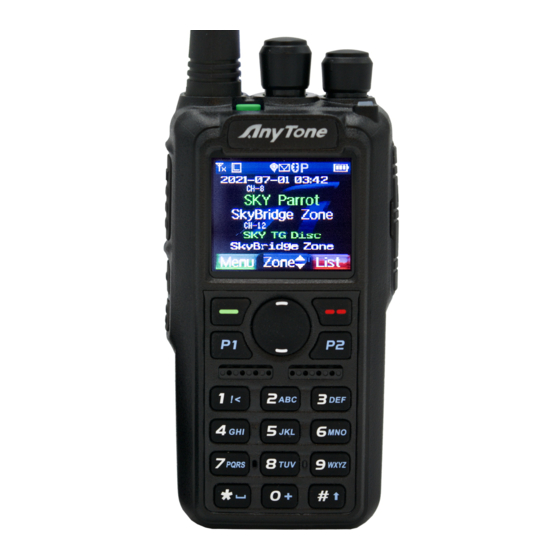
4. RADIO OVERVIEW Emergency Alarm Key (PF3) Channel Switch Antenna POWER/VOL LED Status Indicator Menu key Exit Key P1 key/ P2 key Speaker MIC Input PTT Button Speaker/Mic Jacks [PF1] top Key [PF2] bottom Key Digital DMR and Analog UHF/VHF Two Way Radio... -
Page 18: Status Indications
4. RADIO OVERVIEW Status Indications The top LED will help you to identify the current radio status. LED Indication Status Flashes Red Low battery voltage Constant Red Transmitting Constant Green Analog Receiving Constant Cyan Digital Receiving Flashes Green Scan Programmed Key It is possible to set different functions for [PF1], [PF2], [PF3], keys. - Page 19 4. RADIO OVERVIEW Work Alone Turn on/off the work alone function. During scanning, press the key to skip the unwanted channel Nuisance Delete Digi Monitor In DMR mode, press the key to turn on/off digital monitor Sub CH Hide Turn on/ off the sub channel Prior Zone Switch to Priority Zone Press the key to start or stop the VFO scan.
-
Page 20: Hot Key Setting For Pf1, Pf2, Pf3, P1, P2
4. RADIO OVERVIEW Enable / disable the CTCSS/DCS scanning for the analog channel. When the radio finds matched CTCSS/DCS for current channel, it will CDT Scan open the speaker and start receiving. Only the analog channels with CTCSS/DCS signalling is able to start the CDT scanning. -
Page 21: Basic Operations
5. BASIC OPERATIONS Power on the Radio Turn on the radio by turning the [Power/Volume] switch clockwise till a click is heard, and the LCD displays will show a start-up message, and you will hear a beep after 7 seconds. Adjust Volume Rotate the [Power/Volume] knob to adjust the volume. -
Page 22: New Channel
5. BASIC OPERATIONS Different Color Code: The radio can transmit if the channel is free, but the color code is mismatch. Same Color Code: The radio can transmit only if the channel is free and the color code matches. New channel Press (Menu) to enter main Menu. -
Page 23: Making A Call
5. BASIC OPERATIONS When the call is ended, it will display “Call end”, and you can press [PTT] to respond the call. Making a Call 5.10 Method 1: from the Channel switch. Turn the channel switch to choose a programmed channel. Method 2: from the Talk Group. -
Page 24: Battery Voltage Test
5. BASIC OPERATIONS When the function is on, the radio will start an alarm if the radio is falling to the ground. Raise the radio to stop the alarm. Note: When GPS is on and positioning successfully, it will auto send out the GPS information when the radio starts the alarm. -
Page 25: Advanced Features
6. ADVANCED FEATURES Access Advanced Features for Private Call Method 1: To Access a Private Call from Contact list Press the (Exit) key to enter the Talk Group, press the to a private call ID name. Press Select to View Contact, press Select to see the contact information. - Page 26 6. ADVANCED FEATURES Kill Select Kill, and it will send out a kill signaling to the target radio which will be killed (No display, no operation) when receiving the signaling and it will send back a kill successful message to the transmit radio. Wake Select Wake, and it will send out a wake signaling to the killed radio and the target radio will return to standby when it receives this signaling and...
-
Page 27: Main Menu Functions
7. MAIN MENU FUNCTIONS Talk Group TG List: Will display the talk group list which had been programmed in the PC software. This list is used as a look-up table to display the contact TG information when receiving a call. New Contact: Allows to create a new TG. -
Page 28: Scan
7. MAIN MENU FUNCTIONS 7.4.2 Add Zone Press (Menu) to enter main Menu. Select "Zone". Select "Add Zone". 1. Select "Edit name" Input zone name by keypad, press key to delete. After edit right name, press to confirm and store. 2. -
Page 29: Roaming
7. MAIN MENU FUNCTIONS Edit Scan List Name Select "Edit Name". Input or revise the name and press confirm to store. Store List Delete Channel from Scan List Select "Channel X", then select "Delete CH" to remove it from scan list. 7.5.3 Add Scan List Press (Menu) to enter the main Menu. -
Page 30: Settings
7. MAIN MENU FUNCTIONS Start Roaming: Fixed Time: Starts timed roaming Out of Range: The roaming will be started when the radio cannot find a repeater - "The repeater is out of range" icon will appear 3 times, then the radio will perform roaming one time, and return to roaming off automatically. - Page 31 When the time is reached, the radio will auto exit the menu. Start Display (15) Picture: The radio will display an AnyTone picture when powered on. Character: The radio will display the characters set up in PC software when Digital DMR and Analog UHF/VHF Two Way Radio...
- Page 32 7. MAIN MENU FUNCTIONS powered on. Customer's Pic: The radio will display the picture uploaded by PC software. Digital DMR and Analog UHF/VHF Two Way Radio...
- Page 33 7. MAIN MENU FUNCTIONS In CPS -Tool -Boot Image, it will allow you upload a Power-on Picture. Background (16) Defualt Picture: In standby, the radio will display default picture. Customer's Pic: The radio will display the picture uploaded by PC software.
- Page 34 7. MAIN MENU FUNCTIONS Adjusts the squelch level to receive signal with different signal strength, and a total of 5 levels offered. This function is only valid for analog channel. Power Save (28) Turn on the function to extend the battery life. Save 1:1, work 30ms, dormant 30ms.
- Page 35 7. MAIN MENU FUNCTIONS DTMF Speed (35) Offers DTMF encode speed which will help the receiver decode successfully, 50~500ms are the options. FM Radio (36) Digital DMR and Analog UHF/VHF Two Way Radio...
- Page 36 7. MAIN MENU FUNCTIONS Turn on or off the FM radio. FM Radio Moni (37) Radio Mon On: When FM radio is used, you can still receive or transmit on the channel. Radio Mon Off: When FM radio is used, the radio will not permit a transmission or reception.
- Page 37 7. MAIN MENU FUNCTIONS Squelch Tail Eliminate(STE) setting with CTCSS. Digital DMR and Analog UHF/VHF Two Way Radio...
-
Page 38: Chan Set
7. MAIN MENU FUNCTIONS No-Signal (55) In this case, the Normal Squelch Tail Eliminate(STE) (setting) will be monitored (no signaling) Time Display (57) Set On to show the date/time on display. Set Off to hide the date/time display. Time Zone (58) Set up the time zone of your location. - Page 39 7. MAIN MENU FUNCTIONS D- Digital : Set up to digital channel A+D TX A: Mixed analog, allow receive analog and digital signal, TX is analog. D+A TX D: Mixed digital, allow receive analog and digital signal, TX is digital. TX Power Set up the TX power for current channel.
- Page 40 7. MAIN MENU FUNCTIONS Radio ID (13) In Digital channel, it will show the DMR ID which must be programmed in the PC software – Digital – DMR ID list- DMR ID. Allows edit and select an ID for the channel, each channel allows one ID. In Analog channel, it will show the radio 5Tone self ID or DTMF self ID which is programmed in PC software –...
- Page 41 7. MAIN MENU FUNCTIONS CH Ranging (20) In standby, if the call contact type for a channel is "Private call", The radio will automatically start ranging function when turned to this channel. The other radio's location will be showed on screen at intervals. APRS Receive (21) Turn APRS Receive, if both radio GPS is positioned, the radio will display...
- Page 42 7. MAIN MENU FUNCTIONS RCDT Set up the CTCSS/DCS code for the RX. RTCDT Set up the CTCSS/DCS code for both TX and RX CTCSS code: 62.5Hz~254.1Hz, a total of 51 groups DCS code: 000N~7771, a total of 1024 groups. Optional Signal Allows the setup of DTMF/5TONE/2TONE encode and decode for the Analog channels.
- Page 44 7. MAIN MENU FUNCTIONS DTMF Enc (20) Set a DTMF ID as the default call ID for the current channel. Press the PTT key to transmit the selected DTMF ID. Edit the DTMF ID in Menu or with the PC programing software. DTMF Enc (20) Set a DTMF ID as the default call ID for the current channel.
-
Page 45: Device Info
7. MAIN MENU FUNCTIONS 7.7.3 Device Info Show the Radio ID, Radio name, serial number, model name, frequency range, firmware version, radio data version, latest program date, picture version, language version etc. Record The voice record is designed for security use purpose. Each call will be saved as a separated recording ile with DMR ID and time details. -
Page 46: Gps Positioning Function(Optional With Installed Gps)
7. MAIN MENU FUNCTIONS 7.8.4 Recording Manually In the PC software, Public – Optional Setting – Key function, program a key as Record. Press the programmed Record key, and the radio will start the recording, and speak into the microphone. Select Record Play, and the radio will play the record. -
Page 47: Aprs Location Reporting(Supported By Gps)
7. MAIN MENU FUNCTIONS 7.9.3 Send GPS Information When the GPS is positioning successfully, the GPS icon shows a red color. Follow the above step to check the GPS info, press edit key to Text edit. Press Confirm, and it will display Send or Save. If you select Save, the GPS info will be saved as a draft message. - Page 48 7. MAIN MENU FUNCTIONS Report Channel: Allow user to select a channel to transmit the DMR APRS, please set the 8 report channels in CPS-APRS-Digi page first. Upload Slot: Allow user to select a slot to transmit the DMR APRS. Channel Slot: It uses the slot of current channel ●...
-
Page 49: Digital Monitor
7. MAIN MENU FUNCTIONS Digital Monitor 7.11 Press (Menu) key to enter main menu, press key to choose Digi Moni function. Press Select to enter Digi Moni menu, press key to choose a sub menu. DigiMoni Switch off: Turn off Digital Monitor Single Slot: Monitor the current TS Double Slot: Monitor TS1 and TS2 DigiMoni Cc... -
Page 50: Reset
8. RESET Power off the radio firstly. Then power it on while holding the [PTT] and the [PF1] button below the PTT at the same time. The radio will start up with a note on the display – “Are you sure you want to initialize radio?”... -
Page 51: Trouble Shooting Guide
9. TROUBLE SHOOTING GUIDE Problems Solutions A. Battery pack may not be installed properly. Remove the battery pack The radio cannot be switched and install it again. on or no display after being B. Battery power may be insufficient. switched on. Recharge or replace the battery pack. -
Page 52: Programming Guide
10. PROGRAMMING GUIDE Anytone AT-D878UV(PLUS) radios ship from the manufacturer “Keypad” locked per FCC rules. You can press the (Menu) key and the (star) key to unlock the keypad for the first time of use. You will need the programming cable to connect your radio to your computer for programming. - Page 53 10. PROGRAMMING GUIDE Worldwide Amateur Contact Database The AT-D878UV(PLUS) DMR radios contain a separate database memory for importing and displaying Amateur DMR individual IDs, call sign and user name in comma-delimited format (.csv) Please reference in the programming guide for import and export database operations detailed.
-
Page 54: Line Service And Support
11. ON-LINE SERVICE AND SUPPORT The Anytone website provides additional information about obtaining service or support for the Anytone line of two-way radios and accessories. Visit: www.anytone.net Warning Notes Every effort has been made to ensure that the information in this document is complete, accurate, and up to-date. -
Page 55: Safety
• Do not keep the radio with the antenna very close to, or touching exposed parts of the body, while transmitting. Anytone radios will perform best, if you speak 2-4 inches away from the microphone and the radio is vertical. - Page 56 • Be certain that your power source matches the rating listed for the supplied battery charger (AC adapter). If you are not sure, check with your authorized Anytone dealer. • Avoid damaging the power cable of the battery charger. Do not step on or place anything on it as this could result in a damaged charger power cord.
-
Page 57: Eu Declaration Of Conformity
EU DECLARATION OF CONFORMITY In accordance with EU Directives and Regulations, the undersigned hereby declare that the following equipment is in conformity with the essential requirements of the RE Directive 2014/53/EU. 1. INFORMATION ON THE EQUIPMENT Product: Digital DMR and Analog UHF/VHF Two Way Radio Model Name: AT-D878UV 2. -
Page 58: Technical Specifications
12. TECHNICAL SPECIFICATIONS General Europe: 144-146MHz(V),430-440MHz(U) United State: 136-174MHz(V),400-480MHz(U) Frequency Range Australia: 144-148MHz(V), 420-450MHz(U) India: 144-146MHz(V), 436-438MHz(U) Channel Capacity 4000 channels Channel Spacing 25KHz (Wide Band) ,12.5KHz (Narrow Band) Phase-locked Step 5KHz, 6.25KHz 7.4V DC ±20% /(2100mAh/3100mAh) Operating Voltage Frequency Stability ±2.5ppm Operating Temperature -20℃~ +55℃... - Page 59 European Users should note that operation of this unit in Transmit mode requires the operator to have a valid Amateur Radio Licence from their respective Countries Amateur Radio Licencing Authority for the Frequencies and Transmitter Power levels that this Radio transmits on. Failure to comply may be unlawful and liable for prosecution.
- Page 60 ATTENTION: conditions of use! The band of frequencies on which this device operates is administrated by limitations and/or permissions for their usage. Consequently, in the EU countries mentioned in the sheet, operators must consult the entrusted authorities. In particular, they must possess a license or a frequency assigned to them by their respective competent authority.
Need help?
Do you have a question about the AT-D878UV Plus and is the answer not in the manual?
Questions and answers