Table of Contents
Advertisement
Quick Links
OPERATING MANUAL
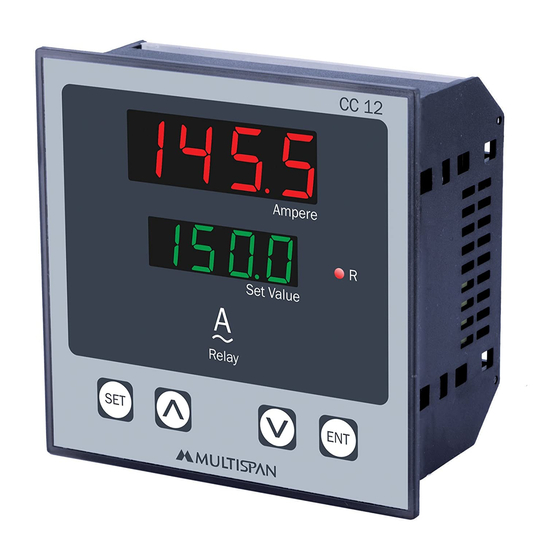
CURRENT CONTROLLER
CC-12
0 0 0. 0
0 0 0. 0
Relay
SET
Working
(1) Do all connection as show in connection diagram and turn ON Instrument.
(2) If low alarm mode is select then starting delay time and delay time both works.
(3) When power ON at that time relay will turn ON after completion of starting delay time.
this delay works only one time after power ON.
(4) When Current values reach at SET value or above SET value at that time
Delay time will be start & after completion of delay time, if process value
Greater than set value relay must be OFF.
(5) When Current values is less than of SET - HYS than relay will be ON.
(6) If high alarm mode is select then only delay time will works.
(7) initially relay in OFF condition and when current value reach at that time relay will
turn ON after completion of delay time.
Connection Diagram
CC-12
Technical Specification
CC 12
Display
Size (mm)
Panel Cutout
Ampere
R
Set Value
Power Supply
ENT
Protection
Operating
Temperature
Relative
Humidity
Input :
Range:
~
~ 100
~
~
100
AUX. SUPPLY
AUX. SUPPLY
100 To
100 To
250V AC
250V AC
50/60 Hz
50/60 HZ
250V AC
250V AC
4VA
4VA
NC
L
N
3
1
2
Model
Micro Controller Based, Double Display
96 (H) X 96 (W) X 50 (D) mm
Input
Output
1 Relay with 1 C/O,230V AC,5A
Range
5 To 1600 CT SELECTABLE AC
100 to 250V AC,50/60 Hz, Approx 4VA
IP-65 (Front side) As per IS/IEC 60529 : 2001
Level
Up to 95% RH Non Condensing
0 to 5 Amp AC
5 to 1600 CT SELE.
!
RELAY
C
NO
5
6
7
4
Page - 1
CC-12
92 X 92 mm
0 To 5Amp AC
0°C To 55°C
0 To 5A AC
I/P
8
9
10
www.multispanindia.com
Advertisement
Table of Contents

Related Manuals for MULTISPAN CC-12


Summary of Contents for MULTISPAN CC-12
- Page 1 OPERATING MANUAL CURRENT CONTROLLER CC-12 Technical Specification Model CC-12 CC 12 Display Micro Controller Based, Double Display Size (mm) 96 (H) X 96 (W) X 50 (D) mm 0 0 0. 0 Panel Cutout 92 X 92 mm Ampere Input 0 To 5Amp AC 0 0 0.
- Page 2 10 sec. Correction Factor C R F C (CF Range: -25.0 to +25.0) 0 0 0. 0 Press & key to set correction factor value Press key for to save & exit CC-12 Page - 2 www.multispanindia.com...
- Page 3 1) The equipment should be cleaned regularly to avoid blockage of ventilating parts. 2) Clean the equipment with a clean soft cloth. Do not use isopropyl alcohol or any other cleaning agent. 3) Fusible resistor must not be replaced by operator. CC-12 Page - 3 www.multispanindia.com...
- Page 4 Note: Product improvement and upgrade is a constant procedure. So for more updated operating information and Support, Please contact our Helpline: +91-9978991474/76/82 or Email at servce@multispanindia.com Ver: 1911 www.multispanindia.com CC-12 Page - 4...
Need help?
Do you have a question about the CC-12 and is the answer not in the manual?
Questions and answers
How to change password for cc12