
Related Manuals for IBM System Storage TS2250


Summary of Contents for IBM System Storage TS2250
- Page 1 IBM System Storage TS2250 Setup, Operator, and Service Guide Machine Type 3580 Model H5S GC27-2275-02...
- Page 3 IBM System Storage TS2250 Setup, Operator, and Service Guide Machine Type 3580 Model H5S GC27-2275-02...
- Page 4 To ensure that you have the latest publications, visit the web at http://www.ibm.com/storage/lto. Released May 2014 This edition applies to the IBM System Storage TS2250 Tape Drive, GC27-2275-02, and to the subsequent releases and modifications until otherwise indicated in new editions.
-
Page 5: Registering For My Support
To register for Support Notification, see http://www-304.ibm.com/jct01004c/systems/support/ storage/news/05072007SupportNotif.html. Sending us your comments ® Your feedback is important in helping IBM provide accurate and useful information. If you have comments or suggestions for improving this publication, send your comments by: v E-mailing IBM: –... - Page 6 TS2250 Tape Drive Setup, Operator and Service manual...
-
Page 7: Summary Of Changes
Added information on the Ethernet interface. 3rd Edition v Added information about the optional tape drive with SAS/USB ports that can be purchased for the tape drive (Feature Codes 5501, 5760, and 5761) © Copyright IBM Corp. 2010, 2014... - Page 8 TS2250 Tape Drive Setup, Operator and Service manual...
-
Page 9: Table Of Contents
Installing a 19-inch rack mount kit (optional) . . 2-2 Bar Code Labels . 4-5 Inspect the Power Cord and Outlet . . 2-3 Handling Cartridges . . 4-7 Position the Tape Drive . . 2-4 Provide Training . 4-7 © Copyright IBM Corp. 2010, 2014... - Page 10 Provide Proper Acclimation and Environmental Removing the Internal Drive . . E-1 Conditions . . 4-7 Manually Removing a Tape Cartridge . . E-4 Perform a Thorough Inspection . 4-7 Before You Begin . . E-5 Handle the Cartridge Carefully .
-
Page 11: Figures
Removing cables from the internal drive 3-1. Inserting a cartridge into the drive E-3. Releasing the drive from the chassis 4-1. The IBM LTO Ultrium Data Cartridge E-4. Sliding the drive forward . . E-4 4-2. Ultrium Data Cartridge on the left; WORM E-5. - Page 12 TS2250 Tape Drive Setup, Operator and Service manual...
-
Page 13: Tables
Ultrium tape drives . . 4-4 C-4. Media supplies . . C-5 4-2. Bar code label requirements for Ultrium C-5. Authorized suppliers of custom bar code tape drives and libraries . . 4-5 labels . C-7 © Copyright IBM Corp. 2010, 2014... - Page 14 TS2250 Tape Drive Setup, Operator and Service manual...
-
Page 15: Safety Notices
Most danger or caution notices contain a reference number (Dxxx or Cxxx). Use the reference number to check the translation in the IBM Systems Safety Notices, G229-9054 manual. The sections that follow define each type of safety notice and give examples. -
Page 16: Completing The Safety Inspection Procedure
The battery is a lithium ion battery. To avoid possible explosion, do not burn. Exchange only with the IBM-approved part. Recycle or discard the battery as instructed by local regulations. In the United States, IBM has a process for the collection of this battery. For information, call 1-800-426-4333. -
Page 17: Class I Laser Product
4. Inspect the power cable for visible cracks, wear, or damage. Figure 1. AC grounding diagram (50 Hz and 60 Hz) Class I laser product Before the library is used, review the following laser safety information. The product might contain a laser assembly that complies with the performance standards set by the US Food and Drug Administration for a Class I laser product. -
Page 18: Rack Safety
Rack safety The following general safety information must be used for all rack mounted devices. DANGER v Always lower the leveling pads on the rack cabinet. v Always install stabilizer brackets on the rack cabinet. v To avoid hazardous conditions because of uneven mechanical loading, always install the heaviest devices in the bottom of the rack cabinet. - Page 19 CAUTION: v Do not install a unit in a rack where the internal rack ambient temperatures might exceed the manufacturer's recommended ambient temperature for all your rack mounted devices. v Do not install a unit in a rack where the air flow is compromised. Ensure that air flow is not blocked or reduced on any side, front, or back of a unit that is used for air flow through the unit.
-
Page 20: Power Cords
(R002) Power cords For your safety, IBM provides a power cord with a grounded attachment plug to use with this IBM product. To avoid electrical shock, always use the power cord and plug with a properly grounded outlet. -
Page 21: End Of Life (Eol) Plan
The cord set should have the appropriate safety approvals for the country in which the equipment will be installed. IBM power cords for a specific country or region are usually available only in that country or region. - Page 22 TS2250 Tape Drive Setup, Operator and Service manual...
-
Page 23: Environmental Notices
Environmental notices The environmental notices that apply to this product are provided in the Environmental Notices and User Guide, Z125-5823-xx manual. A copy of this manual is located on the publications CD. © Copyright IBM Corp. 2010, 2014... - Page 24 xxii TS2250 Tape Drive Setup, Operator and Service manual...
-
Page 25: Preface
Preface This guide describes how to install and use the IBM TS2250 Tape Drive in the following chapters: Chapter 1, “Introduction,” on page 1-1 describes the product, supported servers, operating systems, and device drivers, and lists hardware specifications. Chapter 2, “Installing the drive,” on page 2-1 gives unpacking, set up, and configuration information. - Page 26 (APIs) for each of the various supported operating-system environments. You can obtain this reference at http://www.ibm.com/support/fixcentral. v IBM Translated Safety Notices, 96P0851, provides translation of danger and caution notices. xxiv TS2250 Tape Drive Setup, Operator and Service manual...
-
Page 27: Chapter 1. Introduction
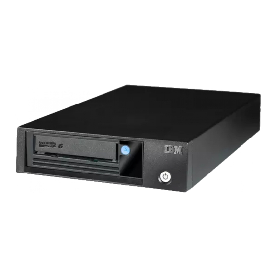
Ultrium series of products, and is available with a Serial Attached SCSI interface (SAS), or with an optional SAS/USB interface. This model incorporates the Linear Tape-Open (LTO) IBM Ultrium 5 Half-High Tape Drive. Figure 1-1. View of the drive... -
Page 28: Front Panel Of The Drive
Front panel of the drive Figure 1-2. Front panel element descriptions Cartridge unload button Fault light (amber) Ready light (green) Single Character Display (SCD) Encryption light (white) SCD dot Drive power button Rear panel of the drive Figure 1-3. Drive rear panel element descriptions - dual SAS ports Power receptacle Fan vent SAS connectors... -
Page 29: Drive Performance
SAS bus capabilities, and system or application software. Cartridge compatibility The TS2250 uses the IBM LTO Ultrium 1500 GB Data Cartridge and is compatible with the cartridges of its predecessor, the IBM TS2240 Tape Drive. The drive performs the following functions:... -
Page 30: Speed Matching
Ultrium 5 drives. In addition to using the IBM LTO Ultrium Data Cartridge with up to 1500 GB capacity, the drive also offers read/write capability for certified LTO Ultrium tape cartridges. -
Page 31: Data Cartridge Capacity Scaling
Data cartridge capacity scaling The SET CAPACITY SCSI command enables a customer to capacity scale a data cartridge to enable faster random access. As an example, a customer could capacity scale a data cartridge to 20% of its normal length which improves the average access time by almost a factor of 5;... -
Page 32: Supported Servers And Operating Systems
Device drivers enable the drive to interact with a variety of servers. To properly install an IBM device driver (if required), refer to the IBM Tape Device Drivers Installation and User's Guide. For applications that use other device drivers, see the application's documentation to determine which drivers to use. -
Page 33: Other Specifications
Other specifications Specification Measurement Maximum altitude for operating and storage 3048 m (10,000 ft) Maximum altitude for shipping 12192 m (40,000 ft) Environmental specifications Measurement Specification Operating Storage Shipping -40 to 60°C Temperature 10 to 40°C (50 to 104°F) -40 to 60°C (-40 to 140°F) (-40 to 140°F) Relative humidity 20 to 80%... - Page 34 TS2250 Tape Drive Setup, Operator and Service manual...
-
Page 35: Chapter 2. Installing The Drive
Unpack the drive and store the packaging for future moves or shipping. Attention: If you return the unit for service, ship it in its original or equivalent packing material, or the warranty may be invalidated. © Copyright IBM Corp. 2010, 2014... -
Page 36: Verify The Shipment
Optional Rack Mount Kit v The IBM System Storage TS2250 Tape Drive Quick Reference (GC27-2276-01) v The IBM System Storage TS2250 Tape Drive Setup, Operator and Service Guide GC27-2275-01 (this guide) v Documentation CD (includes library documentation, translated safety information, and translated warranty information v SAS or USB cables are not part of the ship group. -
Page 37: Inspect The Power Cord And Outlet
Note: All vertical rack measurements are given in rack units (U). One U is equal to 4.45 cm (1.75 in.). The U levels are marked on labels on one front mounting rail and one rear mounting rail. 2. With the sides and back of the shelf facing up, carefully lift the shelf into the rack between the front and back rack rails with the shelf flanges behind the front rack rails. -
Page 38: Position The Tape Drive
For a list of supported adapters and required interposers, visit the web at http://www.ibm.com/storage/lto. Connecting the SAS bus cable The requirements for SAS bus connections are different than for the SCSI bus. Each tape drive is required to have a dedicated bus to the initiator, referred to as point-to-point connection. -
Page 39: Connecting The Usb Interface Cable (Optional)
Figure 2-2. Example of connecting one SAS device to the server Tape drive SAS host adapter card SAS connector Server SAS cable Figure 2-3. Example of connecting the SAS device to two servers Tape drive SAS host adapter card SAS connectors Servers SAS cables 4. -
Page 40: Connect Power
2. Verify that the USB cable is USB 3.0 compatible and has a Type B connector to plug into the tape drive. 3. Connect the USB cable into the host and tape drive as shown. (see Figure 2-4). Figure 2-4. Example of connecting the USB device to the server | | | | | Tape drive USB port... -
Page 41: Configure The Tape Drive To A Server/Host
For instructions about updating firmware from a server that uses an IBM tape device driver, refer to the IBM Tape Device Drivers Installation and User's Guide. To update firmware from a server that uses a non-IBM tape device driver, refer to the documentation for that device driver. - Page 42 The tool scans the host bus and will find and display for selection all IBM LTO devices. The tool will not display and allow for selection any non-IBM device. v Each function has "Help" selection which explains the required syntax as well as a brief explanation of the particular function.
-
Page 43: Register For Support Notification
8. After the drive resets, the new firmware will be loaded on the drive. 9. Remove the ethernet patch cable from the drive's ethernet interface and the computer. Register for Support Notification For information on registering for Support Notification, see “Registering for My Support”... - Page 44 2-10 TS2250 Tape Drive Setup, Operator and Service manual...
-
Page 45: Chapter 3. Operating The Drive
). To copy the dump, see “Function Code 5: Copy Drive Dump” on page 3-12. The SCD Dot is on solid if the dump is in RAM memory. The SCD Dot flashes if the dump is in FLASH memory. © Copyright IBM Corp. 2010, 2014... -
Page 46: Status Lights
The SCD Dot turns off when you obtain a dump (by using ITDT or a SCSI command) or update the drive firmware. Note: If the drive dump is stored in RAM memory (SCD Dot on solid), the dump will be lost when you turn OFF the power or reset the drive. Status Lights The status lights ( 2 , 3 and 4 in “Front panel of the drive”... -
Page 47: Meaning Of Status Lights And Single-Character Display (Scd)
Table 3-1. Meaning of Status Lights and Single-character Display (SCD) (continued) If the and the and the green amber Fault Encryption and the SCD and the SCD Ready Meaning Status Light Status Light is... Dot is... Status is... is... Light is... Flashing If the drive contains a cartridge during (once per... -
Page 48: Unload Button
Table 3-1. Meaning of Status Lights and Single-character Display (SCD) (continued) If the and the and the green amber Fault Encryption and the SCD and the SCD Ready Meaning Status Light Status Light is... Dot is... Status is... is... Light is... Flashing Displaying The drive is updating firmware. -
Page 49: Inserting A Tape Cartridge
Table 3-2. Functions that the Unload Button performs (continued) Unload Button Function How to Initiate the Function Force a drive dump (part of the maintenance mode) Attention: If the drive detects a permanent error and displays an error code, it automatically forces a drive dump (also known as a save of the firmware trace). -
Page 50: Removing A Tape Cartridge
Figure 3-1. Inserting a cartridge into the drive Removing a Tape Cartridge To remove a tape cartridge: 1. Ensure that the drive is powered-on. 2. Press the Unload Button. The drive rewinds the tape and partially ejects the cartridge. The Ready light flashes while the tape rewinds, then goes out before the cartridge partially ejects. -
Page 51: Cleaning The Drive Head
Attention: When cleaning the drive head, use the IBM LTO Ultrium Cleaning Cartridge (see “Media Supplies” on page C-5). You may use another LTO cleaning cartridge, but it may not meet the standards of reliability established by IBM. Clean the drive head whenever displays on the Single-character Display and the Fault light is flashing once per second. -
Page 52: Diagnostic And Maintenance Functions
Table 3-3. Diagnostic and maintenance functions Function Diagnostic or Maintenance Function Instructions Location Code Exit Maintenance Mode: Causes the drive to become “Function Code 0: Maintenance Mode” available for reading and writing data. on page 3-9 Run Drive Diagnostics: Runs tests to determine whether “Function Code 1: Run Drive the drive can properly load and unload cartridges, and Diagnostics”... -
Page 53: Entering Maintenance Mode
Table 3-3. Diagnostic and maintenance functions (continued) Function Diagnostic or Maintenance Function Instructions Location Code Enable Post Error Reporting: When selected, “Function Code P: Post Error Reporting deferred-check conditions are reported to the host. Enabled” on page 3-21 Disable Post Error Reporting: When selected, “Function Code U: Post Error Reporting deferred-check conditions are NOT reported to the host. -
Page 54: Function Code 1: Run Drive Diagnostics
1. Place the drive in Maintenance Mode. For instructions, see“Entering Maintenance Mode” on page 3-9. 2. To exit Maintenance Mode, see “Exiting Maintenance Mode” on page 3-9. The drive exits Maintenance Mode automatically after it completes a maintenance function or after 10 minutes if no action has occurred. Function Code 1: Run Drive Diagnostics Approximate Run Time = 5 minutes per loop Total Number of Loops = 1... -
Page 55: Function Code 2: Update Drive Firmware From Fmr Tape
Appendix A, “Error Codes and Messages,” on page A-1. Push the Unload Button to eject the cartridge. The drive exits Maintenance Mode after the cartridge is removed. Contact IBM Technical Support for problem determination or machine replacement. -
Page 56: Function Code 4: Force A Drive Dump
1. Place the drive in Maintenance Mode. For instructions, see “Entering Maintenance Mode” on page 3-9. 2. Press the Unload Button once per second until appears in the SCD. (If you cycle past the desired code, press the Unload Button once per second until the code reappears.) 3. -
Page 57: Function Code 6: Run Host Interface Wrap Test
example, Gen3 media), error code appears in the SCD. In either case, the tape drive unloads the cartridge and exits Maintenance Mode after the cartridge is removed. 1. Place the drive in Maintenance Mode. (For instructions, see “Entering Maintenance Mode” on page 3-9.) Index through the Maintenance Mode options until is displayed on the SCD. -
Page 58: Function Code 7: Run Rs-422 Wrap Test
Function Code runs a check of the host interface circuitry and host connector on the drive. 1. Make sure that the host interface wrap plug is connected to the host interface connector at the rear of the drive 2. Place the drive in Maintenance Mode. For instructions, see “Entering Maintenance Mode”... -
Page 59: Function Code 8: Unmake Fmr Tape
Note: This function is described here for information only. It is not supported on the TS2250 Tape Drive. This test causes the drive to perform a check of the circuitry and connector for the RS-422 interface. This connector supports the Library Drive Interface (LDI) and the Automation Drive Interface (ADI). -
Page 60: Function Code 9: Display Error Code Log
Note: If you inserted an invalid tape cartridge (for example, Gen2 or WORM media), error code appears in the SCD. If you inserted a write-protected cartridge, or the media has read-only compatibility (for example, Gen3 media), error code appears in the SCD. In either case, the tape drive unloads the cartridge and exits Maintenance Mode after the cartridge is removed. -
Page 61: Function Code E: Test Cartridge & Media
Function Code E: Test Cartridge & Media Approximate Run Time = 15 minutes per loop Total Number of Loops = 10 Function Code performs tests that determine whether a suspect cartridge and its magnetic tape are acceptable. Press Unload to stop the diagnostic test and exit Maintenance Mode. Pressing Unload once aborts the test at the end of the current test loop. -
Page 62: Function Code H: Test Head
Function Code performs tests to ensure that the drive can read from and write to tape. Press Unload to stop the diagnostic test and exit Maintenance Mode. Pressing Unload once aborts the test at the end of the current test loop. Pressing Unload twice aborts the test immediately. -
Page 63: Function Code J: Fast Read/Write Test
of the first loop. Then record the time that it takes for the test to complete. Compare the recorded time with the "Approximate Run Time". If the test runs successfully but the execution time is longer than the "Approximate Run Time", run “Function Code F: Write Performance Test”... -
Page 64: Function Code L: Load/Unload Test
Once you begin this test, the diagnostic test begins the loop sequence. Time the first loop by pressing Unload once to stop the diagnostic test after the completion of the first loop. Then record the time that it takes for the test to complete. Compare the recorded time with the "Approximate Run Time". -
Page 65: Function Code P: Post Error Reporting Enabled
Press Unload to stop the diagnostic test and exit Maintenance Mode. Pressing Unload once aborts the test at the end of the current test loop. Pressing Unload twice aborts the test immediately. Wait for the drive to rewind the tape and unload the cartridge. -
Page 66: Function Code U: Post Error Reporting Disabled
5. Press the Unload Button once per second to select another Maintenance Mode Function. To exit Maintenance Mode, refer to “Exiting Maintenance Mode” on page 3-9. Function Code U: Post Error Reporting Disabled When Post Error Reporting is disabled, deferred-check conditions are not reported to the host and temporary errors are not reported in the sense data. -
Page 67: Chapter 4. Using Ultrium Media
IBM LTO Ultrium tape cartridges. You may use other LTO-certified data cartridges, but they may not meet the standards of reliability that are established by IBM. The IBM LTO Ultrium Data Cartridge can not be used in other IBM non-LTO Ultrium tape products. -
Page 68: Types Of Cartridges
Cartridge Memory Chip (LTO-CM) All generations of the IBM LTO Ultrium Data Cartridges include a Linear Tape-Open Cartridge Memory (LTO-CM) chip ( 1 in Figure 4-1 on page 4-1), that... -
Page 69: Worm (Write Once, Read Many) Cartridge
To control the capacity of the cartridge (for example, to obtain a faster seek time) issue the SCSI command SET CAPACITY. For information about this command, refer to the IBM System Storage Ultrium Tape Drive SCSI Reference. WORM (Write Once, Read Many) Cartridge Certain records retention and data security applications require a Write Once, Read Many (WORM) method for storing data on tape. -
Page 70: Cleaning Cartridge
“Media Supplies” on page C-5). Cleaning Cartridge A specially labeled IBM LTO Ultrium Cleaning Cartridge is used to clean the drive head. The drive itself determines when a head needs to be cleaned. To clean the head, insert the cleaning cartridge into the tape drive. The cleaning is performed automatically. -
Page 71: Bar Code Labels
Tape cartridges can be ordered with the labels included or with custom labels. To order tape cartridges and bar code labels, see “Media Supplies” on page C-5. The bar code for usage in IBM tape libraries must meet predefined specifications. They include (but are not limited to):... -
Page 72: Sample Bar Code Label On The Lto Ultrium
Guidelines for Using Bar Code Labels Apply the following guidelines whenever using bar code labels: v Use only IBM-approved bar code labels on cartridges to be used in an IBM tape library. v Do not reuse a label or reapply a used label over an existing label. -
Page 73: Handling Cartridges
Incorrect handling or an incorrect environment can damage cartridges or their magnetic tape. To avoid damage to your tape cartridges and to ensure the continued high reliability of your IBM LTO Ultrium Tape Drives, use the following guidelines. Provide Training v Post procedures that describe proper media handling in places where people gather. -
Page 74: Handle The Cartridge Carefully
dislodged. Go to Appendix D, “Repairing a Cartridge,” on page D-1. Figure 4-4. Checking for gaps in the seams of a cartridge v Check that the leader pin is properly seated (see 2 in Figure D-2 on page D-2). v If you suspect that the cartridge has been mishandled but it appears usable, copy any data onto a good cartridge immediately for possible data recovery. -
Page 75: Tape Cartridges In A Turtlecase
Figure 4-5. Tape cartridges in a Turtlecase v Never ship a cartridge in a commercial shipping envelope. Always place it in a box or package. v If you ship the cartridge in a cardboard box or a box of a sturdy material, ensure the following: –... -
Page 76: Environmental And Shipping Specifications For Tape Cartridges
Environmental and Shipping Specifications for Tape Cartridges Before you use a tape cartridge, acclimate it to the operating environment to prevent condensation in the drive (the time will vary, depending on the environmental extremes to which the cartridge was exposed). The best storage container for the cartridges (until they are opened) is the original shipping container. -
Page 77: Chapter 5. Troubleshooting
If you encounter problems when running the drive, refer to the flowchart in Figure 5-1. For explanations of codes on the Single-character Display (SCD), see “Single-character Display (SCD)” on page 3-1. Please review the“Pre-Call Checklist” on page 5-4 before calling IBM Technical Support. Start 1. Try another electrical outlet. -
Page 78: Procedure 2: Inspecting A Cartridge For Damage
For instructions about updating firmware from a server that uses an IBM tape device driver, refer to the IBM Tape Device Drivers Installation and User's Guide. To update firmware from a server that uses a non-IBM tape device driver, refer to the documentation for that device driver. -
Page 79: Procedure 3: Checking Sas Host Connections
2. If your cartridge does not eject properly, contact your service representative. (IBM service personnel should go to Appendix E, “Information for Trained Service Personnel,” on page E-1.) Procedure 3: Checking SAS Host Connections Check the host connections for your drive by following the steps below. -
Page 80: Resolving Problems Reported By The Server
If you have questions or problems, go through this checklist before contacting IBM Technical Support. Ensure that the total SAS cable length does not exceed 5.5m (18 ft). Perform the following steps before you place a call to IBM Technical Support. Where instructions refer you to the web, visit http://www.ibm.com/storage/lto. -
Page 81: Replacing The Tape Drive
3. Verify that your device drivers are at the most recent level: v For IBM device drivers, visit the web. v For the device drivers of independent software vendors (ISVs), visit the appropriate third-party web site. - Page 82 PART NUMBER 19P5941 ATTENTION: 1. A Repair ID tag maintains the original serial number record of the machine and allows IBM to entitle the machine for future maintenance or warranty service. Mail in exchange requires the completion and securing a Repair ID tag (part number 19P5941) to the replacement unit.
-
Page 83: Appendix A. Error Codes And Messages
4. If the proper voltages are being applied, power off/on the tape drive to see if the problem repeats. 5. Replace the tape drive if the problem persists. The error code clears when you place the tape drive in maintenance mode. © Copyright IBM Corp. 2010, 2014... -
Page 84: Error Codes On The Single-Character Display
2. Power the tape drive off and on, then retry the operation that produced the error. 3. If the problem persists, download new firmware and retry the operation. 4. If the problem persists, send the drive dump that you collected in step 1 to your IBM Support Center. - Page 85 Table A-1. Error codes on the Single-character Display (continued) Error Code Cause and Action For Problems with Writing Data: If the problem occurred while the tape drive was writing data to the tape, retry the operation with a different cartridge: v If the operation succeeds, the original cartridge was defective.
- Page 86 Table A-1. Error codes on the Single-character Display (continued) Error Code Cause and Action Media error. The tape drive determined an error occurred because of a faulty tape cartridge or an invalid tape cartridge. Ensure the tape cartridge is the correct media type: v Ultrium 1 and Ultrium 2 cartridges are not supported in the Ultrium 5 tape drive.
- Page 87 Table A-1. Error codes on the Single-character Display (continued) Error Code Cause and Action Degraded operation. The tape drive determined that a problem occurred which degraded the operation of the tape drive, but it did not restrict continued use. If the problem persists, determine whether the problem is with the drive or the media.
- Page 88 1. Check the host application to ensure the host application is providing the correct encryption key. v Refer to the IBM LTO Ultrium Tape Drive SCSI Reference documentation for the Sense Data returned for an encryption operation. v Retry the encryption operation after the host application problems have been resolved.
-
Page 89: Appendix B. Tapealert Flags
The server reads the flags from Log Sense Page 0x2E. Refer to the IBM LTO Ultrium Tape Drive SCSI Reference for the list of TapeAlert flags that are supported by this tape drive. - Page 90 TS2250 Tape Drive Setup, Operator and Service manual...
-
Page 91: Appendix C. Ordering Optional Features, Replacement Parts, Power Cords, And Media
TS2250 (3580 H5S) Half High Bridgebox CRU - SAS/USB ports 95P4587 2 m SAS/Mini-SAS 1x Cable 95P4488 2 m Mini-SAS/Mini-SAS 1x Cable 95P6566 SAS wrap tool 05H5080 USB3 cable, 2.7m, Type A-B CRU 12X4292 1.0 m Mini-SAS/Mini-SAS 1x Cable © Copyright IBM Corp. 2010, 2014... - Page 92 Power Cords To avoid electrical shock, a power cord with a grounded attachment plug has been provided. Use only properly grounded outlets. The table below lists the power cord part number, feature code, the country or region where the power cord can be used, and the plug's standard reference.
- Page 93 Table C-3. Power Cords (continued) Description, Feature Plug Standard Country or Region Index Number in Code (FC), and Part Reference Figure C-1 on page C-5 Number (PN) Denmark DK2-5A Denmark v 2.8 m, 250V v FC 9821 v PN 39M5130 South Africa SABS 164 Bangladesh, Burma, Pakistan, South Africa, Sri Lanka...
-
Page 94: Power Cords
Table C-3. Power Cords (continued) Description, Feature Plug Standard Country or Region Index Number in Code (FC), and Part Reference Figure C-1 on page C-5 Number (PN) Korea HV** KS C8305, Korea K60884-1 v 2.8 m, 250V v FC 9844 v PN 39M5219 India HV** IS 6538... -
Page 95: Types Of Receptacles
Figure C-1. Types of Receptacles Media Supplies To find the closest IBM-authorized distributor, visit the web at http://www.ibm.com/storage/media or call 1-888-IBM-MEDIA. Table C-4. Media supplies Order by Machine Type / Model Order by Part Number (P/N) from Item Type Description... - Page 96 The LTO Ultrium 5 Tape Drives do not require cartridge bar code labels. However, if you use your data cartridges or cleaning cartridges in an IBM tape library product, you may need cartridge bar code labels if your tape library product requires them.
-
Page 97: Authorized Suppliers Of Custom Bar Code
You can order bar code labels directly from the authorized label suppliers listed in the table below. Table C-5. Authorized suppliers of custom bar code labels In America In Europe and Asia Tri-Optic EDP Europe, Ltd. Broomfield, CO U. K. U. - Page 98 TS2250 Tape Drive Setup, Operator and Service manual...
-
Page 99: Appendix D. Repairing A Cartridge
If the leader pin in your cartridge becomes dislodged from its pin-retaining spring clips or detaches from the tape, you must use the IBM Leader Pin Reattachment Kit (part number 08L9129) to reposition or reattach it. (Do not reattach the pin if you must remove more than seven meters (23 feet) of leader tape.) The sections... -
Page 100: Leader Pin In The Incorrect And Correct
Figure D-1. Leader pin in the incorrect and correct positions. The cartridge door is open and the leader pin is visible inside the cartridge. To reposition the leader pin, refer to Figure D-2 and perform the steps below. 1. Slide open the cartridge door ( 1 ) and locate the leader pin ( 2 ) Note: If necessary, shake the cartridge gently to roll the pin toward the door. -
Page 101: Reattaching A Leader Pin
To rewind the tape, refer to Figure D-3 and perform the steps below. 1. Insert the cartridge manual rewind tool ( 1 ) into the cartridge's hub ( 2 ) and turn it clockwise until the tape becomes taut. 2. Remove the rewind tool by pulling it away from the cartridge. 3. -
Page 102: Attaching The Leader Pin Attach Tool To The Cartridge
Pin supplies ( 3 ). Leader pins and C-clips. Attention: v Use only the IBM Leader Pin Reattachment Kit to reattach the leader pin to the tape. Other methods of reattaching the pin will damage the tape, the drive, or both. - Page 103 until you see the end of the tape inside the cartridge. Then, slowly turn the rewind tool counterclockwise to bring the tape edge toward the cartridge door ( 3 ). 2. Continue to turn the rewind tool counterclockwise until approximately 13 cm (5 in.) of tape hangs from the cartridge door.
- Page 104 2. Place a new C-clip into the retention groove ( 2 ) on the leader pin attachment tool and make sure that the clip's open side faces up. 3. Place the leader pin that was removed earlier into the cavity ( 3 ) of the leader pin attach tool.
-
Page 105: Attaching The Leader Pin To The Tape
Figure D-8. Attaching the leader pin to the tape Appendix D. Repairing a Cartridge... - Page 106 TS2250 Tape Drive Setup, Operator and Service manual...
-
Page 107: Appendix E. Information For Trained Service Personnel
Appendix E. Information for Trained Service Personnel Attention It is strongly recommended that the drive and stuck tape be returned to IBM for removal and recovery. v These procedures must be performed only by a trained IBM service provider. SSRs should claim their time against service code 33 ECA 013 when performing this procedure. -
Page 108: Removing The Screws That Secure The Cover
Figure E-1. Removing the screws that secure the cover and internal drive 5. Return the unit to its upright position. 6. Gently push on the drive's rear panel to remove the chassis from the cover (see Figure E-2 on page E-3). TS2250 Tape Drive Setup, Operator and Service manual... -
Page 109: Removing Cables From The Internal Drive
Step 2. Remove the Internal Drive Figure E-2. Removing cables from the internal drive 1. Unplug the SAS interface cable and the ethernet interface cable ( 1 and 2 in Figure E-2) from the drive. Disconnecting the internal SAS interface cable disconnects both the SAS interface and electrical power from the drive. -
Page 110: Manually Removing A Tape Cartridge
Attention v The best solution for recovering data on a damaged cartridge is to send it to IBM for professional data recovery. v Before using this procedure, you must have exhausted all other means of removing the tape cartridge from the drive. Use this procedure only if you cannot remove the tape cartridge by using any other means. -
Page 111: Before You Begin
v The following removal procedures can destroy customer data! Use extreme care when handling or removing the customer’s tape cartridges to minimize tape damage and lost data. v DO NOT TOUCH the magnetic tape or tape path. Both are extremely sensitive to the oil and salt from your skin. -
Page 112: Tape Spooled Off Supply Reel
3. Ground yourself to the drive by using the ESD Kit. 4. Remove the cover of the drive by performing the following steps: a. To remove the drive bezel, pull the right side of the bezel from the front of the drive, then pull the left side of the bezel out of the frame of the drive. -
Page 113: Rewinding Tape Into Cartridge
4. Moisten a cotton swab with water and wet approximately 13 mm (0.5 in.) of the tape end and feed it onto the supply reel (inside the cartridge). 5. Turn the supply reel ( 4 in Figure E-6) clockwise, allowing the moistened tape to adhere to the hub as it winds around the supply reel (inside the cartridge). -
Page 114: Tape Pulled From Or Broken Near Leader Pin
Tape Pulled from or Broken near Leader Pin Figure E-7. Drive with cover removed to reveal gear train. Threader Threader Loader motor intermediate mechanism worm gear gear gear 1. Pull out tape from the takeup reel. Note: If there is more than approximately 0.6 m (2 ft.) of tape on the takeup reel, go to “Tape Broken in Mid-tape”... -
Page 115: Tape Broken In Mid-Tape
out of the cartridge. Figure E-8. Leader Block Assembly (LBA) Loader motor worm gear Leader block assembly (LBA) 8. Rotate the loader motor worm gear ( 3 in Figure E-7 on page E-8) counterclockwise as viewed from the front of the drive until it stops. 9. -
Page 116: Tape Tangled Along Tape Path
Figure E-9. Rewinding tape into cartridge Loader motor worm gear Takeup reel motor Outer guide rail Supply reel motor WARNING: DO NOT TOUCH 7. Reassemble the drive by reversing the procedure in Step 4 in “Beginning Procedure” on page E-5. 8. -
Page 117: No Apparent Failure Or Damage To Tape
Figure E-10. Rewinding tape into cartridge Loader motor worm gear Takeup reel motor Outer guide rail Supply reel motor WARNING: DO NOT TOUCH 3. Turn the supply reel ( 4 in Figure E-10) clockwise. 4. Continue spooling into the cartridge until the tape is taut and remains within the flanges of the tape guiding rollers. -
Page 118: Rewinding Tape Into Cartridge
Figure E-11. Rewinding tape into cartridge Loader motor worm gear Takeup reel motor Outer guide rail Supply reel motor WARNING: DO NOT TOUCH 2. Begin spooling the tape back into the cartridge by turning the supply reel motor ( 4 in Figure E-11) clockwise. 3. -
Page 119: Cartridge
Figure E-12. Drive with cover removed to reveal gear train. Threader Threader Loader motor intermediate mechanism worm gear gear gear 5. As the leader pin is secured in the cartridge, you should hear the leader pin retention spring clips click into place. If you do not hear the click, continue rolling until the threader intermediate gear ( 1 in Figure E-12) stops. - Page 120 9. Remove the cartridge from the cartridge loader tray. 10. Reassemble the drive by reversing the procedure in Step 4 in “Beginning Procedure” on page E-5. 11. Reassemble the drive chassis by reversing the steps in “Removing a Drive from an Enclosure” on page E-1. 12.
-
Page 121: Notices
Consult your local IBM representative for information on the products and services currently available in your area. Any reference to an IBM product, program, or service is not intended to state or imply that only that IBM product, program, or service may be used. Any functionally equivalent product, program, or service that does not infringe any IBM intellectual property right may be used instead. -
Page 122: Trademarks
The materials at those Web sites are not part of the materials for this IBM product and use of those Web sites is at your own risk. IBM may use or distribute any of the information you supply in any way it believes appropriate without incurring any obligation to you. -
Page 123: Electronic Emission Notices
If these and other IBM trademarked terms are marked on their first occurrence in this information with a trademark symbol ((R) or (TM)), these symbols indicate U.S. registered or common law trademarks owned by IBM at the time this information was published. Such trademarks may also be registered or common law trademarks in other countries. -
Page 124: Industry Canada Compliance Statement
Klasse A ein. Um dieses sicherzustellen, sind die Geräte wie in den Handbüchern beschrieben zu installieren und zu betreiben. Des Weiteren dürfen auch nur von der IBM empfohlene Kabel angeschlossen werden. IBM übernimmt keine Verantwortung für TS2250 Tape Drive Setup, Operator and Service manual... -
Page 125: People's Republic Of China Class A Electronic Emission Statement
Einhaltung der Schutzanforderungen, wenn das Produkt ohne Zustimmung der IBM verändert bzw. wenn Erweiterungskomponenten von Fremdherstellern ohne Empfehlung der IBM gesteckt/eingebaut werden. EN 55022 Klasse A Geräte müssen mit folgendem Warnhinweis versehen werden: "Warnung: Dieses ist eine Einrichtung der Klasse A. Diese Einrichtung kann im Wohnbereich Funk-Störungen verursachen;... -
Page 126: Taiwan Class A Compliance Statement
Taiwan Class A compliance statement Taiwan contact information This topic contains the product service contact information for Taiwan. IBM Taiwan Product Service Contact Information: IBM Taiwan Corporation 3F, No 7, Song Ren Rd., Taipei Taiwan Tel: 0800-016-888 Japan VCCI Council Class A statement... -
Page 127: Japan Electronics And Information Technology Industries Association (Jeita) Statement (Greater Than 20 A Per Phase
Japan Electronics and Information Technology Industries Association (JEITA) statement (greater than 20 A per phase) Korean Communications Commission (KCC) Class A Statement Russia Electromagnetic Interference (EMI) Class A statement Notices... - Page 128 TS2250 Tape Drive Setup, Operator and Service manual...
-
Page 129: Glossary
A circuit board that adds function to a computer. Adjustment. Advanced Interactive Executive. IBM’s implementation of the UNIX operating system. The RS/6000 system, among others, uses AIX as it's operating system. alphanumeric Pertaining to a character set that contains letters, numerals, and usually other characters, such as punctuation marks. - Page 130 assignment The naming of a specific device to perform a function. asynchronous Pertaining to two or more processes that do not depend upon the occurrence of specific events such as common timing signals. attention (notice) A word for calling attention to the possibility of danger to a program, device, or system, or to data.
- Page 131 cartridge manual rewind tool A device that can be fitted into the reel of a cartridge and used to rewind tape into or out of the cartridge. cartridge storage slot Individual slot located within a magazine that is used to house tape cartridges.
- Page 132 data Any representations such as characters or analog quantities to which meaning is or might be assigned. data buffer The storage buffer in the control unit. This buffer is used to increase the data transfer rate between the control unit and the channel. data cartridge A tape cartridge dedicated to storing data.
- Page 133 drive, magnetic tape A mechanism for moving magnetic tape and controlling its movement. Drive. Data security erase. Digital signal processor. EBCDIC Extended binary-coded decimal interchange code. Edge connector. Engineering change. Error correction code. EEPROM Electrically erasable programmable read-only memory. Electronics Industries Association. EIA unit A unit of measure, established by the Electronic Industries Association, equal to 44.45 millimeters (1.75 inches).
- Page 134 field replaceable unit (FRU) An assembly that is replaced in its entirety when any one of its components fails. file A named set of records stored or processed as a unit. Also referred to as a dataset. file protection The processes and procedures established in an information system that are designed to inhibit unauthorized access to, contamination of, or deletion of a file.
- Page 135 IBM Ultrium Tape Drive Located within the library, a data-storage device that controls the movement of the magnetic tape in an IBM LTO Ultrium Tape Cartridge. The drive houses the mechanism (drive head) that reads and writes data to the tape.
- Page 136 Light-emitting diode. Linear Tape-Open (LTO) A type of tape storage technology developed by the IBM Corporation, Hewlett-Packard, and Certance. LTO technology is an “open format” technology, which means that its users will have multiple sources of product and media. The “open” nature of LTO technology enables compatibility between different vendors' offerings by ensuring that vendors comply with verification standards.
- Page 137 Pertaining to the bar code on the bar code label of the IBM Ultrium Tape Cartridge, a 2-character code, L1, that represents information about the cartridge. L identifies the cartridge as one that can be read by devices which incorporate LTO technology;...
- Page 138 modifier That which changes the meaning. mount a device To assign an I/O device with a request to the operator. Microprocessor. Millisecond. Message. multipath Pertaining to using more than one path. Not applicable. node In a network, a point at which one or more functional units connect channels or data circuits.
- Page 139 Portable Document Format. Parity error. Product engineer. pick Pertaining to the library, to remove, by means of a robotic device, a tape cartridge from a storage slot or drive. picker A robotic mechanism located inside the library that moves cartridges between the cartridge storage slots and the drive.
- Page 140 robot Picker. robotics Picker assembly. Request for price quotation. Read/write. Seconds of time. Service Action Code. Code developed to indicate possible FRU or FRU's to replace to repair the hardware. Serial attached SCSI interface. scratch cartridge A data cartridge that contains no useful data, but can be written to with new data.
-
Page 141: Tape Cartridge
v Ultra160 SCSI: Uses a 16-bit bus and supports data rates of 80 or 160 MBps. Sense. special feature A feature that can be ordered to enhance the capability, storage capacity, or performance of a product, but is not essential for its basic work. Service representative, see also CE. - Page 142 Variations of the USB interface have different data transmission rates. The variations include: USB 1.1, USB 2.0, USB 3.0. unload Prepare the tape cartridge for removal from the drive. utilities Utility programs. utility programs A computer program in general support of the processes of a computer; for instance, a diagnostic program.
- Page 143 3-12 shipping specifications 4-10 front panel features 1-2 disabling post error reporting 3-22 training 4-7 display error code log 3-16 Media 4-1 enabling post error reporting 3-21 Capacity scaling 1-5 © Copyright IBM Corp. 2010, 2014...
- Page 144 Media (continued) SAS Host connections Write-Protect Switch inserting 3-5 checking 5-3 setting 4-2 mid-tape recovery 3-6 Server connection removing 3-6 configuring 2-7 resolving problems 5-4 Servers supported 1-6 Message codes A-1 servers, supported 1-6 My Support iii Service procedures E-1 Shipment verify 2-2 Verify shipment 2-2...
- Page 145 IBM business partner, or your authorized remarketer. When you send comments to IBM, you grant IBM a nonexclusive right to use or distribute your comments in any way it believes appropriate without incurring any obligation to you. IBM or any other organizations will only use the personal information that you supply to contact you about the issues that you state on this form.
- Page 146 Readers’ Comments — We'd Like to Hear from You Cut or Fold Along Line GC27-2275-02 Fold and Tape Please do not staple Fold and Tape _ _ _ _ _ _ _ _ _ _ _ _ _ _ _ _ _ _ _ _ _ _ _ _ _ _ _ _ _ _ _ _ _ _ _ _ _ _ _ _ _ _ _ _ _ _ _ _ _ _ _ _ _ _ _ _ _ _ _ _ _ _ _ _ _ _ _ _ _ _ _ _ _ _ _ _ _ _ _ _ _ _ _ _ _ _ _ _ _ NO POSTAGE NECESSARY IF MAILED IN THE...
- Page 148 Part Number: 46C2120 Printed in USA GC27-2275-02...
Need help?
Do you have a question about the System Storage TS2250 and is the answer not in the manual?
Questions and answers