Lauda PROLINE Kryomats RP 4050 C Operation Manual
Hide thumbs
Also See for PROLINE Kryomats RP 4050 C:
- Operating instructions manual (115 pages) ,
- Operating instructions manual (136 pages)

Related Manuals for Lauda PROLINE Kryomats RP 4050 C


Summary of Contents for Lauda PROLINE Kryomats RP 4050 C
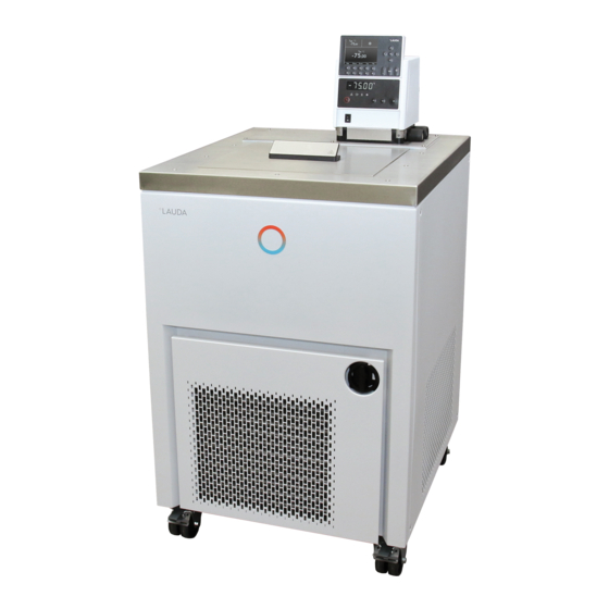
- Page 1 Operation manual PROLINE Kryomats Low-temperature thermostats with SmartCool System RP 4050 C, RP 4050 CW RP 3090 C, RP 3090 CW RP 4090 C, RP 4090 CW Release 03/2022 j Read the instructions before starting work!
- Page 2 Manufacturer LAUDA DR. R. WOBSER GMBH & CO. KG Laudaplatz 1 97922 Lauda-Königshofen Germany Phone: +49 (0)9343 503-0 Fax: +49 (0)9343 503-222 E-Mail info@lauda.de Internet https://www.lauda.de Translation of the original operating instructions Q4DA-E_13-010-EN; replaces release 08/2020 i, 11/2018 e, 10/2018 d, 05/2016 b2, 03/13, 01/09, 06/08 Valid from: software control system (Master) version 2.13...
-
Page 3: Prefixed Safety Notes
Prefixed safety notes Before operating the equipment, please read carefully all the instructions and safety notes in Section 1. If you have any questions, please phone us! Follow the instructions on setting up, operation etc. This is the only way to avoid incorrect operation of the equipment and to ensure full warranty protection. -
Page 4: Table Of Contents
Contents Prefixed safety notes ..................................3 SAFETY INFORMATION ............................8 ..............................8 AFETY INFORMATION ............................. 9 ENERAL SAFETY INFORMATION ............................10 THER SAFETY INFORMATION BRIEF OPERATING INSTRUCTIONS ........................11 ............................12 ENU STRUCTURE ASTER ....................13 ENU STRUCTURE OMMAND EMOTE ONTROL CONTROLS AND FUNCTIONAL ELEMENTS .................... - Page 5 ..............................39 AINS CONNECTION ................................39 WITCHING ON ............................41 WITCHING OFF STANDBY ................................41 EY FUNCTIONS 7.4.1 General key functions and pilot lamps ......................... 41 7.4.2 Changing window information............................45 7.4.3 Locking the keyboard ..............................46 ..............................48 MPORTANT SETTINGS 7.5.1 Temperature setpoint setting ............................
- Page 6 7.12.4 High-level warning or alarm ............................92 7.12.5 Pump-motor supervision: Overload or blockage ....................... 93 7.12.6 Pump-motor supervision: Dry running ........................93 7.12.7 Compressor Overtemp ..............................94 7.12.8 Three-phase current ..............................94 7.12.9 Fault list „Alarms and Warnings“ ..........................95 INTERFACE MODULES ............................
- Page 7 ....................119 ELP DESK AND ORDERING REPLACEMENT PARTS ACCESSORIES ................................. 120 TECHNICAL DATA AND DIAGRAMS........................ 121 DECLARATION OF CONFORMITY AND PRODUCT RETURNS DECLARATION ....... 130 INDEX ..................................132 03/2022 Proline Kryomats 7 / 137...
-
Page 8: Safety Information
Safety information Safety information Type and source Consequences of non-compliance Action 1 Action ... Danger! "DANGER" indicates an immediate dangerous situation which – if the safety requirements are ignored – may result in fatal or severe, irreversible injuries. Type and source Consequences of non-compliance Action 1... -
Page 9: General Safety Information
Reference Refers to further information in other sections. Note Here special attention is drawn to some aspect. General safety information A heating and cooling thermostat heats or cools and circulates heat transfer liquids according to specified parameters. This involves hazards due to high or low temperatures, fire and general hazards due to the application of electrical energy. -
Page 10: Other Safety Information
Standards). « Cet appareil numérique de la Classe A est conforme à la norme NMB-003 du Canada ». Other safety information Only connect equipment to PE grounded mains sockets. At higher operating temperatures, parts of the bath cover can reach surface temperatures exceeding 70 °C. Be careful when touching it! ... -
Page 11: Brief Operating Instructions
Brief operating instructions These brief instructions shall give you the possibility to operate the unit quickly. For safe operation of the unit, it is necessary to read carefully all the instructions and safety notes! 1. Assemble unit and add items as appropriate ( 6.1). The unit may NEVER be overturned nor put upside down! Take care of the hose tubing connections (... -
Page 12: Menu Structure: Master
Menu structure: Master Display flashes. Set setpoint Setpoint Bath temperature with °C °C Display is accepted after 4 sec. 2%32 or proceed immediately with the key: ( 7.5.1) Pump power.5-8/Standby.0 External temperature °C °C 2%02 Display flashes. Set value with Display is accepted after 4 sec. -
Page 13: Menu Structure: Command Remote Control
Menu structure: Command Remote Control Pump Level 0, 5…8 intern Pt100 Calibration Menu External pump extern Pt100 Default Start unfill condense. All Modules all default Calibration Master All default Works settings Command Only control par. int. Resolution Cool Only control par. ext. Device status Other connected Only miscellaneous... -
Page 14: Controls And Functional Elements
Controls and functional elements Command remote control (see page 15) Rotary switch for power supply Master control element Grille (on both sides) Pump connection on the side and Bypass valve Front cover (closed) (see illustration on this page). Four steering transport rollers, two off them with Bath cover stoppers Pump connection on the side:... - Page 15 With the front panel open, access to the drain cock: Bath drain tap Bath drain nozzle Bath edge heating and bath bridge heating Connection cable LiBus for control head Nameplate Connection bath bridge heating Mains cable Cooling water connections (at water-cooled devices W only), connections as per pictogram Connection cable for control head 03/2022...
- Page 16 Pt100 temperature probe Suction nozzle (return to bath) & pump outflow or pressure output Connection socket LiBus (LAUDA internal bus) for bus refer to housing for label suitable for unit and to which the refrigerating lower section...
- Page 17 Control element: Master Display Heater active (yellow LED is lit) The temperature of an external source is displayed Bath controlled by external temperature source (EXT is lit green). (green LED is lit) Enter key Error signal (red LED is blinking) Select keys Overtemperature set point to check or set Tmax Cooler active (blue LED is lit)
-
Page 18: Unit Description
Unit description Environmental conditions The operation of the thermostats is only allowed under the following conditions as specified in DIN EN 61010-2-010:2003 and DIN EN 61010-1:2001: Indoor use only. Altitude up to 2000 m above sea level. Foundation must be dense, even, non-slippery and non-flammable. ... -
Page 19: Materials
The pump connections on the unit are fitted with M16 x 1 thread. The Varioflex pump operates short-term up to viscosity of 150 mm²/s. In the closed-loop control mode 50 mm²/s should not be exceeded. The temperature control is the best with 30 mm²/s and lower viscosity. For operation as a circulating thermostat with an external load, the highest possible power level is practicable to maintain the temperature difference low, among other things also with higher temperatures in conjunction with oils as heat transfer liquid. -
Page 20: Programmer And Ramp Function
The device is equipped in series with the following sockets: One socket (10S) for the connection of an external Pt100 temperature probe. Two sockets (70S) for the connection of components via the LAUDA equipment bus (cooling section, Command remote control, external solenoid valve, etc.). -
Page 21: Refrigerating Unit
3. Contact Module (Order No. LRZ 915) on 15-pole SUB-D socket. With three relay contact outputs (changeover, max. 30 V / 0.2 A) and three binary inputs for control via external voltage-free contacts. Plug 15-pole (Order No. EQM 030) and plug case (Order No. EQG 017). Further details can be found in section 8.5. -
Page 22: Unpacking
After unpacking, first check the device and accessories for any damage in transit. If, contrary to expectations, there is visible damage to the unit, the shipper must be immediately informed, so that an investigation can be made. Please also inform the LAUDA Service (Contact 9.3.6). 22 / 137... -
Page 23: Standard Accessories
Packing and unpacking with original packaging material 5.3.1 Background For the customer to allow a properly packaging, e.g. for further transport or return transport to LAUDA. To repack the unit carefully and properly, it is necessary to store the original package! ... -
Page 24: Unpacking The Device
5.3.3 Unpacking the device 5.3.3.1 Outer cardboard box Open the cardboard box on top. Pallet Take out the filling material and the accessory parts. Draw out the four nails on the edge, which fix the cardboard box on the pallet. 24 / 137 Proline Kryomats 03/2022... -
Page 25: Lift Device From The Pallet
Remove the outer cardboard box vertically upwards. 5.3.3.2 Lift device from the pallet Two textile round slings Attention: The round slings must not press against the structure of the device! Pay attention to the center of gravity of the device! 03/2022 Proline Kryomats 25 / 137... -
Page 26: Repacking With Original Packing Material
Textile round slings Align the wheels on the device length. Textile round slings 5.3.4 Repacking with original packing material The packaging of a device takes place in the reverse order. In-plant transport with hand pellet truck or fork lifter ... -
Page 27: Before Preparation
Transport the device on a hand pellet truck. Transport the device with a fork lifter. Before preparation Remove the protective foil. For installation and commissioning, the operating instructions must be observed! 03/2022 Proline Kryomats 27 / 137... -
Page 28: Preparation
Preparation Assembly and siting Falling down / falling over of the device on inclined plane / table edge Crushing of the hands and feet Only position the device on level surfaces and not close to Warning! table edges. Tilting the device by additional load on the device Crushing of the hands and feet ... -
Page 29: Filling And Draining
Site the unit on a flat surface The unit must not be put into operation if its temperature during storage or transport has dropped below the dew point. Wait for about one hour. The unit may NEVER be overturned nor put upside down! ... - Page 30 When selecting the heat transfer liquid, observe the admissible temperature range. Caution! Only use LAUDA heat transfer liquids. Overfilling containers, spilling heat transfer liquid Notice Environmental hazard from leaking heat transfer liquid Note the thermal volume expansion of the heat transfer ...
-
Page 31: Connection Of The Cooling Water
Draining Contact with hot / cold heat transfer liquid Scalds, frostbite Bring heat transfer liquids to room temperature before draining. Caution! Make sure that the drain tap is closed after draining. Delay in boiling and thermal decomposition due to liquid residues Burns, scalds, development of harmful vapors Remove all old heat transfer liquid completely from the bath, ... -
Page 32: Heat Transfer Liquids, Cooling Water And Hoses
Heat transfer liquids, cooling water and hoses a) Heat transfer liquids Temper- Viscosity LAUDA Chemical Viscosity Flash Packing drum ature (kin) at designation designation (kin) point Order number range temperature from °C mm²/s mm²/s 10 L 20 L to °C at 20 °C... - Page 33 Observe the safety data sheets for the various heat transfer liquids. If required, you can download the safety data sheets from our homepage. Open the LAUDA homepage, tap Services Download center. In the Download center, chose the [Safety data sheet] option in the [Document type] drop-down list.
- Page 34 Ammonia (NH Not permissible Iron (Fe), dissolved < 0.2 mg/L Manganese (Mn), dissolved < 0.05 mg/L Aluminum (Al), dissolved < 0.2 mg/L Free aggressive carbonic acid (CO Not permissible Hydrogen sulfide (H Not permissible Algae growth Not permissible Suspended matter Not permissible Risk to the environment due to oil contamination of the cooling water circuit With a leaky condenser there is the danger that refrigerating machine oil from the coolant circuit of the cooling...
-
Page 35: Connecting External Loads
Metal hoses in non-rusting stainless steel, with union nut M16 x 1, internal width 10 mm. Type Length (cm) Temperature range °C Field of application Order number MK 50 -90 – 150 LZM 052 With foam insulation for MK 100 -90 –... - Page 36 The external application must not have a hydraulically blocking effect. If cross-sectional area of tube is too low temperature gradient between bath and external load due to low flow rate. Always ensure the largest possible passages in the external circuit. ...
-
Page 37: Starting Up
Starting up Addition of liquids with low boiling points (e.g. water to hot oil), alteration of liquid properties (reducing the flash point) Explosion, burns, scalds, fire Warning! Site the device in suitable premises. Avoid dripping water and condensation. Do not position any small parts and liquids above the device. - Page 38 Pay attention to the permitted temperature range when selecting heat transfer liquid. Caution! Only use LAUDA heat transfer liquids. Skin contact with heat transfer liquid or hot / cold surfaces Burns, scalds, frost bite, impacts, cuts, snagging Only operate the device with its housing.
-
Page 39: Mains Connection
Mains connection Use of inadmissible mains voltage or frequency Notice Property damage Compare the rating label with the available mains voltage and frequency. Compare the rating on the nameplate (back of control head and behind the front panel) with the mains voltage. ... - Page 40 The unit starts its self-test. All display segments and symbols appear for about Self-test 1 second. °C 88((( The momentary bath temperature is displayed, Bath temperature the pump starts provided "Standby" or "Manual start" ( 7.6.1) has not been °C 02%32 programmed,...
-
Page 41: Switching Off / Standby
The dialog language also can be changed later via Display English Settings Basic settings Language Sounds Master Deutsch Mark the required language with Sounds Command Français Language Español Confirm the selection with Master-Mode Autostart Current Consumpt. - Page 42 Speeds up entry by moving the counting position to the left: a) Keys are pressed and held down or b) one of the two keys is pressed and held down, followed immediately by brief pressing of the other key. Moves counting position to the right: ...
- Page 43 Standby activation (pump, heater and refrigerating machine are deactivated when the yellow LED is lit). However, timer continues to run! Refer to safety information in 7.5.3. Duo key: Top: decimal-point key. Bottom: key for arithmetical sign. ...
- Page 44 1. Basic window with the three most important °C items of information: 55.3 Y(%) , current bath temperature, , setpoint of the bath or external °C temperature, Standby Information: Heating/ cooling. Here, e.g. heating is taking place at 55.3% and 0.0% cooling.
-
Page 45: Changing Window Information
3. Super window with seven items of information: °C °C 55,3 T , current bath temperature. Y(%) T , setpoint. °C T , current temperature on external probe (if connected). Overtemperature cut-off point T Pump °C ... -
Page 46: Locking The Keyboard
Open the unit parameter menu via the soft Basic Window Edit key Menu . Standard Window Default Super Window With change from Settings Display Data Standard Window Edit Pump Menu takes you to the illustrated window. ... - Page 47 SAFE flashes briefly and the display returns to the actual temperature. The Master keyboard is now locked. °C SAFE SAFE The display signals the locked state when any Master key is pressed. Unlocking: SAFE and hold For three seconds, then appears.
-
Page 48: Important Settings
Important settings 7.5.1 Temperature setpoint setting The setpoint is the temperature, which the thermostat should reach and maintain constant. Master (main level) Press key until (Setpoint) appears. Press key, display flashes. Enter the setpoint with the two keys ( 7.4.1 General key functions and pilot lamps). - Page 49 Command or T or the soft key opens the setpoint window. 123.45 is the setpoint, which is still active. The upper and lower limit temperatures are displayed (device-specific values). Enter new setpoint: There are three different possible entry 123, methods: 1.
-
Page 50: Displaying The Actual External Temperature
Select desired position with the cursor keys (black background). Enter new setpoint: With the soft key Edit open the window 123, shown on the left. Enter fixed temperature setpoint as described Min: -40.00°C Max:202.00°C above and accept into the list with or cancel with ... -
Page 51: Setting Pump Power Or Standby
Master EXT Switches to the actual-value display of the external temperature probe (or to the actual value received from an interface module 7.5.4). is lit in green next to the row of figures. If no external Pt100 probe is connected, °C 02%02 -----... - Page 52 Display flashes 4 s new value is automatically accepted, or Wait 4 seconds or value is immediately accepted with Enter key. Command Pump Level Open the device parameter menu via the soft Pump Level Level 8 Menu .
-
Page 53: Activate External Pump
7.5.4 Activate external pump As an option an external pump is available for the Proline Kryomats for external applications. This pump can be set on / off manually in the menu shown below. Another possibility is the automatic mode. In this case the pump is switched according to the unit status standby / running. - Page 54 Change temperature probe source: for the internal probe, only when an external probe is connected, only when an analog module is connected and configured, only when a serial module is connected and is continuously receiving actual values from a PC.
-
Page 55: Current Consumption From The Mains
7.5.6 Current consumption from the mains It is not possible to reduce the power consumption of the Proline Kryomats! Command Current Consumption Open the device parameter menu via the soft Display 16.0 A Sounds Master Menu . Sounds Command ... -
Page 56: Setting The Date And Time
7.5.7 Setting the date and time Command Clock Time Date Open the device parameter menu via the soft Pump Set time Settings Set date Menu . Graph Timer 1 With the cursor keys continue to: Clock Timer 2 Clock Set time Programmer... -
Page 57: Display Resolution Setting
7.5.8 Display resolution setting The Command remote control allows for different resolutions of the displayed temperature. Command Display resolution Open the device parameter menu via the soft Pump Calibration Works settings Settings Menu . Resolution Graph With the cursor keys continue to Device status Clock Settings... -
Page 58: Special Settings
Special settings 7.6.1 Defining the type of start mode Usually it is desirable that the thermostat carries on operating again after an interruption in the voltage supply. However, if for safety reasons you do not wish this, you can insert an intervening manual activation step. Command Auto start ... -
Page 59: Defining Temperature Limits
7.6.2 Defining temperature limits With this function, it is possible to define a minimum and a maximum temperature in which the thermostat controls. By reaching the temperature limits, a warning appears. In this way setpoint input can be prevented which may damage the heat transfer liquid or the apparatus. -
Page 60: Setpoint Offset Operating Mode
7.6.3 Setpoint offset operating mode With this function it is possible to apply an offset value to the temperature provided by the external temperature probe or a module and then to use it as the setpoint. The bath temperature can, for example, be operated at -25 °C below the temperature of a reactor, which is being measured by the external temperature probe. -
Page 61: Restoring Works Settings
7.6.4 Restoring works settings All works settings, apart from the control parameters and the sensor calibration, are restored. Command Works settings Open the device parameter menu via the soft all default All modules Menu . only control par. int Master only control par. -
Page 62: Setting The Volume Of The Acoustic Signals
7.6.5 Setting the volume of the acoustic signals The LAUDA Proline Thermostats signal alarms as a dual-tone acoustic signal and warnings as a continuous tone. Command Sounds Open the device parameter menu via the soft Menu . Alarm loud ... -
Page 63: Restoring The Works Setting Of The Internal Temperature-Probe Offset
The temperature measurement device shows the true temperature value (with glass Temperature value of the ref. thermometers consider the correction where temp. measurement device: applicable!). Change the display in the adjacent window to the true value with cursor or soft keys and accept with or End , Min: -50.0°C... -
Page 64: Entering The Offset Of The External Temperature Probe
7.6.8 Entering the offset of the external temperature probe If a deviation is found during the check using a calibrated reference thermometer, then the offset (the additive part of the characteristic) of the external measurement chain can be adjusted with the following function. The reference thermometer must be dipped nearly by the external temperature probe into the consumer bath according to the details on the calibration certificate. -
Page 65: Graphical Display Of Temperature Measurements
Graphical display of temperature measurements Command Screen and Graph 25.00 25.01 25.02 Press the soft key Screen a number of times T °C 27.00 as required until the graph recorder window appears. 26.00 With the soft key Graph you enter the menu 25.00 for the configuration of the graph recorder. - Page 66 Temp. scale defines how the scaling is to be Mode Temp. min 22.00 carried out: Displayed value Temp. max 27.00 automatic , by the program, or Legend Sample Time manual in that you yourself define the limits Time axis with the next menu point.
-
Page 67: Programmer
Programmer Almost any temperature/time profile can be created with the programmer. A desired bath temperature can be approached as quickly as possible or via a defined ramp. Furthermore, the pump level and the behavior of the switching outputs can be defined. Five temperature/time programs are provided for free programming. Each program consists of a number of temperature/time segments. - Page 68 Each program begins with the segment "Start". It defines at which temperature Segment 1 is to continue the program. It is not possible to specify a time for the Start segment. For thermostats without cooling ability, the start temperature must be selected higher than the bath temperature, which prevails before the program start.
-
Page 69: Selecting And Starting The Program (Start, Hold, Stop)
7.8.2 Selecting and starting the program (Start, Hold, Stop) Here you will learn how to select and start a program that has already been created. If no program has been created ( 7.8.4) “Creating or modifying a program (Edit)”. Command Programmer Program 1 ... -
Page 70: Interrupting, Continuing Or Terminating The Program (Hold, Continue, Stop)
Once the start has been confirmed with Hold Status Prog. 1 running appears at the bottom. Stop Edit Loops Graph Info Pump Menu Prog.1 running 7.8.3 Interrupting, continuing or terminating the program (Hold, Continue, Stop) Command Programmer Program 1 Status ... -
Page 71: Creating Or Modifying A Program (Edit)
Continue In addition, the standby key stops the Status Stop programmer. The pump, heater and cooling unit Edit are switched off. Loops Graph Follow the safety information ( 7.5.3). Info After pressing the standby key again, the programmer returns to the previously selected operating mode: Pause or active operation depending on what was previously selected. - Page 72 Command Programmer Program1 Edit Modify In the Edit menu one Status Modify Modify Delete a program. Delete Edit Loops Press the key. Graph Info Continue to Modify . with the key There is the possibility of modifying single segments, i.e.
- Page 73 Then continue with to the pump and signal Pump Out 1 Out 2 Out 3 output setting. Start ------- ------- ------- ------- The right-hand part of the entry table appears ------- ------- ------- as shown on the left. ...
- Page 74 If the field in the column "Tolerance" has a black background, the entry mode for the "Temperature tolerance" is obtained by Temp. tolerance (0=off): pressing the key. It defines how accurately the end of segment temperature is to be obtained before the next segment is processed.
- Page 75 The contact outputs of the contact module (if ------- Contact out present, special accessory) are programmed open here. closed If the field in the column "Out 1" has a black background, the entry mode for the Contact output is obtained by pressing the key.
-
Page 76: Defining The Number Of Program Loops (Loops)
7.8.5 Defining the number of program loops (Loops) Command Programmer Program1 Loops If required, programs can be looped many Status times. Edit Loops With access the menu Loops Graph Select the number of desired program loops. Info Pump Menu... -
Page 77: Obtaining Information On A Program (Info)
The display of the programmed temperature T °C 27.00 curve can be quit with or End . 26.00 25.00 24.00 23.00 00:00 00:45 01:30 02:15 Pump Menu 7.8.7 Obtaining information on a program (Info) Command Programmer Program1 Info ... -
Page 78: Ramp Function
Ramp function With the ramp function, temperature changes over any time period can be conveniently entered. This is especially advantageous with very low temperature changes (e.g. 0.1 °C/ day). Example: From the current outflow temperature (e.g. 242.4 °C) 200 °C of cooling is to occur over 5 days. Then 200 °C is entered as the temperature change, the time value 5 is entered for the time and day(s) selected as the time unit. -
Page 79: Timer Function
7.10 Timer function Using the timer function, the thermostat can carry out an action at a certain time or after a certain waiting period. The actions are: switching on the thermostat, entering the standby mode or one of the 5 programs in the programmer. Command Clock Timer 1 Timer 2... -
Page 80: Control Parameters
Weekplan Arrange takes you to the Weekplan window shown on the left. Time Action Time Action Monday 07:30 Start 17:00 ------- Using the cursor keys select the field, Tuesday 10:00 Prog.4 17:00 ------- which is to be filled in. Wednesday 08:00 ------- 17:00 ------- ... -
Page 81: Internal Control Variable (Integral Measurement Probe)
7.11.1 Internal control variable (integral measurement probe) Only read further here, if you have no external temperature probe connected (and activated according to Section 7.5.4 as control variable). Command Control Parameters Open the device parameter menu via the soft Control Parameters Menu . -
Page 82: Steps For Setting The Control Parameters For External Control
When a setpoint step change is specified, it may be that the optimum control would set a bath temperature, which might significantly exceed the temperature desired on the external vessel. There is a correction limitation, which specifies the maximum permissible deviation between the temperature on the external load and the heat transfer liquid temperature. - Page 83 +2°C +95°C vessel size and the heat transfer Ethanol Minimum +40°C liquid Tools to watch the time behavior: Graph mode of the Command remote control, LAUDA Wintherm PC- program. 03/2022 Proline Kryomats 83 / 137...
-
Page 84: Internal And External Control Parameter Sets
7.11.3 Internal and external control parameter sets If a thermostat is used for a number of applications, which always leads to a change of the control parameters, these control parameters (up to 9 sets) can be saved in the thermostat and activated again as required. Also saving is useful for finding the best control parameters;... -
Page 85: Self Adaption
Editing the control parameter sets The change in the control parameters is explained in Section 7.11.1 / 7.11.2 (internal / external). Once the value has been changed and confirmed, the set number, e.g. Set 3 Upload actual , the new value is accepted into the control parameter set to be changed (Set 3) via the command Control parameter sets 7.11.4 Self Adaption... - Page 86 The window shown adjacent appears. Start Status With the menu Status the test run of the Setpoint Self Adaption can be started. When the Self Identification Adaption is finished, the test run will be Actual Parameters terminated automatically. ...
- Page 87 With the menu Actual Parameters Store in Set 9 Status actual set control parameters can be stored Setpoint in parameter set 9. Identification After the test run the detected control Actual Parameters parameters will be taken over as control parameters automatically.
-
Page 88: Alarms, Warnings And Errors
Switch of the unit at the rotary mains switch. If the error is always present after switching on the device, please give information to the LAUDA Service ( 9.5). Find cause of alarm or warning and rectify where necessary. Then press on the Master keyboard in order to remove the alarm message. - Page 89 Setting the overtemperature cut-off: Recommended setting: 5 °C above desired bath temperature. Caution!! The overheat switch-off point T is controlled by a system functioning independently of the bath control. Setting of the nominal temperature, however, can be limited via the functions T and T (...
-
Page 90: Low-Level Alarm And Low-Level Checking
With this test, the bath temperature must not be below 0 °C or above 50 °C, otherwise there is a risk of injury! If irregularities arise during the checking of the safety devices, switch off the unit immediately and pull out the mains plug. Have the equipment checked by LAUDA Service. Command Low-level alarm! Low-level alarm! is shown in the display and signifies that unlocking is only ... -
Page 91: High-Level Settings
7.12.3 High-level settings Different reactions can be chosen when the level sensor detects the height of the heat transfer liquid level. Depending on the setup, heat transfer liquid or operation conditions, one of the following settings may be suitable: Master Command Setting Reaction and application recommendation... -
Page 92: High-Level Warning Or Alarm
7.12.4 High-level warning or alarm Acoustic warning signal sounds for 3 seconds when the liquid level rises so far that the uppermost switching point of the level sensor has been reached. 3 Sec. Or in case the warning function as described in 7.12.3 was chosen: ... -
Page 93: Pump-Motor Supervision: Overload Or Blockage
7.12.5 Pump-motor supervision: Overload or blockage The SelfCheck Assistant monitors the Varioflex pump: 1. Alarm sounds as dual-tone signal for pump-motor overload or blockage. bL0C 2. Display of signals blockage. Pump alarm °C bL0C 3. The red LED above the fault triangle flashes. -
Page 94: Compressor Overtemp
This error may affect stage 1 (Error 68) or stage 2 (Error 69). If the error is always present after switching on the device, please give information to the LAUDA Service ( 9.5). 7.12.8 Three-phase current Command Error! Three-phase current ... -
Page 95: Fault List „Alarms And Warnings
7.12.9 Fault list „Alarms and Warnings“ Alarms Message Meaning Pump too fast (low level) PuLEU Low level alarm in the level sensor LEUEL Overtemperature (t > tmax) tEMNP Pump blocked (no rotation) bL0C Command remote control connection interrupt CFA1L Temperature signal of external Pt100 missing Temperature signal of analogue input missing Temperature signal of serial port missing Analogue module: Current input 1 interrupted... - Page 96 Software version of valve 3 too old Software version of valve 3 too old WX 20 WX120 Software version of pump 0 too old Software version of pump 0 too old WX 21 WX121 Software version of pump 1 too old Software version of pump 1 too old WX 22 WX122...
- Page 97 Software version of heating system too old Software version of heating system too old WX413 WX513 Software version of RS 232 too old Software version of analogue interface too old WX415 WX514 Software version of contact I/0 too old Software version of contact I/0 too old WX416 WX516 Software version of valve 0 too old...
-
Page 98: Interface Modules
Interface modules Installing of modules Live parts when installing interfaces Electric shock Disconnect the device from the mains power supply before installing interfaces. Warning! The installation must only be performed by a specialist. When switching off only on the master head, using the switch at the front or back, there is still voltage ... -
Page 99: Menu Structure For All Modules
Menu structure for all modules All existing menu points are illustrated. However, the Command remote control masks out menu points, which cannot be executed. Further information can be found in the following sections. RS232 Menu RS485 Setpoint temperature 2400 Ext. actual temp. 4800 Interfaces 9600... -
Page 100: Serial Interface Rs 232/485
RS 232/485 Interface Module (order no. LRZ 913) with 9-pole SUB-D socket. Electrically isolated by optocoupler. With the LAUDA instruction set essentially compatible to the Ecoline and Integral Series. The RS 232 interface can be connected directly to the PC with a 1:1 through-contact cable (order no. EKS 037). -
Page 101: Protocol Rs 232
8.3.2 Protocol RS 232 The interface operates with one stop bit, no parity bit and 8 data bits. Transfer rate either 2400, 4800, 9600 (factory setting) or 19200 baud as selected. The RS 232 interface can be operated with or without hardware handshake, (RTS/CTS). ... -
Page 102: Protocol Rs 485
This termination network is usually incorporated on the PC plug-in card (RS 485). 8.3.4 Protocol RS 485 The interface operates with one stop bit, no parity bit and 8 data bits. Transfer rate either 2400, 4800, 9600 (Factory setting) or 19200 baud as selected. ... - Page 103 Command Explanation OUT_MODE_00_X Keyboard Master: 0 = free / 1 = locked (corresponds to “KEY”). OUT_MODE_01_X Control: 0 = internal / 1 = external Pt100 / 2 = external analogue / 3 = external serial / 5 = external Ethernet / 6 = external EtherCAT. Note: With some temperature control devices this command can only be carried out if the command OUT_PV_05_XXX.XX has been sent by the interface.
-
Page 104: Read Commands (Data Requested From The Thermostat)
8.3.6 Read commands (Data requested from the thermostat) Command Explanation IN_PV_00 Read bath temperature (outflow temperature). IN_PV_01 Indication of the controlled temperature (internal / external Pt / external Analogue / external serial). IN_PV_03 Read external temperature TE (Pt100). IN_PV_04 Read external temperature TE (Analogue input). IN_PV_05 Read bath level. - Page 105 Command Explanation VERSION_B Read software type of Command. VERSION_T Read software type of cooling system. VERSION_A Read software type of analogue module. VERSION_V Read software type of RS 232/485 module. VERSION_D Read software type of digital module. VERSION_M_0 Read software type of solenoid valve (cooling water). VERSION_M_1 Read software type of solenoid valve (automatic refill).
-
Page 106: Error Messages
National Instruments program development tool LABVIEW ® (http://sine.ni.com/apps/we/nioc.vp?cid=1381&lang=US). In order to make program operation possible on the RS 232/485 interface, LAUDA provides drivers specially ® designed for LABVIEW which can be downloaded free of charge under https://www.lauda.de/en/. -
Page 107: Analogue Module
Analogue module The analogue module (order no. LRZ 912) has 2 inputs and 2 outputs, which are brought out on a 6-pole socket to Namur Recommendation (NE28). The inputs and outputs can be set independently as 0 – 20 mA, 4 – 20 mA or 0 – 10 V interface. -
Page 108: Contact Module
View of the socket (front) or solder side of plug: Socket 74S (from May 2010 onwards) Pin 1 Output 1 Pin 2 Output 2 Pin 3 0 V reference potential Pin 4 Input 1 Pin 5 +20 V (max. 0.1 A) Pin 6 Input 2 ... -
Page 109: Namur-Contact Module Lrz 914 With Only One Input And One Output
Contact module LRZ 915; SUB-D Output Input 4 5 6 13 14 15 Contact inputs and outputs View of the socket from the plug side or of the plug on the solder side. A suitable 15-pole Sub-D plug can be obtained together with a suitable housing: Order no. -
Page 110: Maintenance
Maintenance Device status The thermostat can be conveniently checked with the Command remote control. 9.1.1 Interrogating the device type Settings Device status Device type 9.1.2 Software version Settings Device status Software version The versions of the control system ( Control ), safety system ( Safety... -
Page 111: Fault Memory
9.1.5 Fault memory For the analysis and localization of faults the Command version includes a fault memory in which up to 45 fault and alarm messages are saved. Command Error store Settings Device status Error No. Source Code Type Date Time ... -
Page 112: Draining The Water-Cooled Condenser
9.2.2 Draining the water-cooled condenser Important: With the risk of frost (e.g. transport in winter), drain the condenser on water-cooled devices. Remove the water hose on the water tap. Than open the solenoid valve for the water as described below. Blow compressed air in the water return hose Continue until all water has flowed out of the device. -
Page 113: Servicing
Have repairs carried out only by a specialist. 9.3.1 Servicing LAUDA Thermostats largely require no service. If the heat transfer liquid becomes contaminated, it should be replaced ( 6.2). At the back of the Master head a main fuse switch is located which interrupts the mains connection when an overload occurs. -
Page 114: Service Intervals
9.3.2 Service intervals System part Frequency Comment Each time of putting into operation and then Complete device External condition of the device Monthly Heat transfer liquid Analysis of the heat transfer liquid Half-yearly (and as required) ( 9.3.3) Heat transfer system Sealing Daily External visual inspection... -
Page 115: Cleaning The Condenser
9.3.4 Cleaning the condenser 9.3.4.1 Air-cooled condenser Contact with sharp slats on the condenser during cleaning Cutting Clean the condenser using suitable resources such as a hand Caution! brush or compressed air. The SmartCool System refrigerating machine operates largely without servicing. So that the full cooling power is available, the heat exchanger (condenser) should cleaned of dust at intervals of one month or longer depending on the operating period and dust level in the ambient air. -
Page 116: Decalcifying The Water Cooling Circuit
Allow at least 30 liters of water to flow through. 9.3.5 Repair information If you need to send in a unit for repair, it is essential to first contact the LAUDA Service ( 9.5). When sending in the unit, ensure that it is carefully and properly packed. LAUDA cannot be held liable for any damage caused by improper packing. -
Page 117: Remedying Faults
9.3.6 Remedying faults Before you contact the LAUDA Service, check whether the problem can be remedied with the following instructions: Fault Possible remedy Device does not cool or only very slowly. 1. The module "Smart Cool" is set to "off" Switch on "Smart Cool"... -
Page 118: Disposal Information
Command: Pump blocked temperature. (Pump motor monitoring: Overload, blockage). 2. The pump is blocked. Contact the LAUDA Service 7.12.5. 9.5. PulEU 1. No liquid in the system. If this occurs, the level Master: Alarm message monitoring has failed. -
Page 119: Disposal Of The Packaging
Telephone: +49 (0)9343 503-350 (English and German) Fax: +49 (0)9343 503-283 E-mail service@lauda.de We are available any time for your queries and suggestions. LAUDA DR. R. WOBSER GMBH & CO. KG Laudaplatz 1 97922 Lauda-Königshofen Germany Telefone: +49 (0)9343 503-0... -
Page 120: Accessories
Raising platforms, application frames etc. We will inform you about other accessories on request. Also, refer to our special and accessory broachers. LiBus = LAUDA internal BUS (based on CAN). 120 / 137 Proline Kryomats 03/2022... -
Page 121: Technical Data And Diagrams
Technical data and diagrams The figures have been determined according to DIN 12876. Table 1 RP 4050 C RP 4050 CW Operating temperature- ACC range °C -50 – 200 Ambient temperature range °C 5 – 40 Relative humidity maximum relative humidity 80 % for temperatures up to 31 °C, decreasing linearly to 50 % relative humidity at 40 °C Device distance to the surroundings Temperature range for storage... - Page 122 Table 1 RP 4050 C RP 4050 CW Flow rate max. (pressure) L/min 19 at pump power level 8 Hose connections Thread M16 x 1; olives 13 mm external diameter Bath volume from – to 32 – 44 Bath opening B x L 350 x 350 Bath depth / usable depth 250 / 230...
- Page 123 Table 2 RP 3090 C RP 3090 CW RP 4090 C RP 4090 CW Operating temperature - ACC range °C -90 – 200 Ambient temperature range °C 5 – 40 Relative humidity maximum relative humidity 80 % for temperatures up to 31 °C, decreasing linearly to 50 % relative humidity at 40 °C Device distance to the surroundings Temperature range for storage...
- Page 124 Table 2 RP 3090 C RP 3090 CW RP 4090 C RP 4090 CW Pump type Pressure pump, 4 power levels (level 5 to 8) Discharge pressure max. 0.5 at pump power level 8 Flow rate max. (pressure) L/min 19 at pump power level 8 Hose connections Thread M16 x 1;...
- Page 125 Proline Kryomat with external pump Catalogue number L001669 L001674 L001695 L001670 L001675 L001698 L001671 L001693 L001699 L001673 L001694 L002583 Operating temperature - ACC range °C -40 - 150 Pressure (bar) (L/min) Flow rate ACC range is the working temperature range during operation with an active cooling unit. 03/2022 Proline Kryomats 125 / 137...
- Page 126 Proline Kryomat with external pump Catalogue number L001661 L001667 L001690 L001662 L001685 L001691 L001663 L001686 L003524 L001665 L001687 L003525 L001666 Operating temperature - ACC range °C -90 - 150 Pressure (bar) (L/min) Flow rate ACC range is the working temperature range during operation with an active cooling unit. 126 / 137 Proline Kryomats 03/2022...
- Page 127 Mains connection data Proline Kryomat air-cooled Mains connection data RP 4050 C RP 3090 C RP 4090 C 400 V +8/-10 %; 3/N/PE~50 Hz 208 V ±8 %; 3/PE~60 Hz 200 V ±10 %; 3/PE~50/60 Hz Proline Kryomat water-cooled Mains connection data RP 4050 CW RP 3090 CW RP 4090 CW...
- Page 128 Pump characteristics measured with water internal pump PL 4 Pressure L/min Flow rate Cooling curves 128 / 137 Proline Kryomats 03/2022...
- Page 129 Cooling curves; Bath closed; Heat transfer liquid: Ethanol; Time in minutes; Temperature in °C. Influence of ambient temperature at air-cooled Kryomats 03/2022 Proline Kryomats 129 / 137...
-
Page 130: Declaration Of Conformity And Product Returns Declaration
Declaration of conformity and product returns declaration 130 / 137 Proline Kryomats 03/2022... - Page 131 03/2022 Proline Kryomats 131 / 137...
-
Page 132: Index
Index Delete ............72 Hazards ............9 Heat transfer liquid Device data.......... 110 Selection ..........32 Device status ........110 Accessories ........... 120 Setpoint ..........48 Dewing ............ 21 Acoustic signals ........62 testing..........114 Dirt trap..........115 Activate standby ........51 Viscosity .......... - Page 133 Safety functions ........88 Safety information ........8 T end °C ..........72 Offset source ........60 Safety notes ..........3 Technical data ........121 Offset, temperature probe ....62 Safety system ......... 19 tEMNP Overtemperature alarm ... 89 Out 1 (Program) ........75 Screen displays ........
- Page 134 134 / 137 Proline Kryomats 03/2022...
- Page 136 Manufacturer LAUDA DR. R. WOBSER GMBH & CO. KG ◦ Laudaplatz 1 ◦ 97922 Lauda-Königshofen Telephone: +49 (0)9343 503-0 ◦ Fax: +49 (0)9343 503-222 E-mail: info@lauda.de ◦ Internet: https://www.lauda.de...
Need help?
Do you have a question about the PROLINE Kryomats RP 4050 C and is the answer not in the manual?
Questions and answers