Table of Contents
Advertisement
Quick Links
Repair and Parts
®
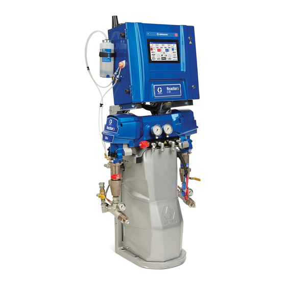
Reactor
Electric, heated, plural component proportioner for spraying polyurethane foam and
polyurea coatings. For indoor use only. Not approved for use in explosive atmospheres or
hazardous (classified) locations. Only use with Reactor 3 heated hoses. For professional
use only.
See pages 4 and 5 for model information, including
maximum working pressure and approvals.
Important Safety Instructions
Read all warnings and instructions in this
manual and in related manuals before
using the equipment. Save these
instructions.
3 Proportioning Systems
3A8501A
EN
Advertisement
Table of Contents

Related Manuals for Graco Reactor 3


Summary of Contents for Graco Reactor 3
- Page 1 Electric, heated, plural component proportioner for spraying polyurethane foam and polyurea coatings. For indoor use only. Not approved for use in explosive atmospheres or hazardous (classified) locations. Only use with Reactor 3 heated hoses. For professional use only. See pages 4 and 5 for model information, including maximum working pressure and approvals.
-
Page 2: Table Of Contents
Reactor E-XP2 ........80 ® Graco Extended Warranty for Reactor Components ..81... -
Page 3: Supplied Manuals
Fusion PC Spray Gun, Instructions 312666 Fusion CS Spray Gun, Instructions 309856 Fusion MP Spray Gun, Instructions-Parts 313213 ® Probler P2 Gun, Instructions Reactor Connect Manual 3A8504 Reactor Connect, Instructions Heated Hose Manual 3A7683 Reactor Heated Hose (Reactor 3), Instructions 3A8501A... -
Page 4: Models
Models Reactor E-20 and E-30 E-20 Standard E-20 Pro 7 E-20 Pro 10 E-20 Elite 10 E-30 Standard E-30 Pro 10 E-30 Pro 15 E-30 Elite 15 Model (Part Number) 7 kW (26R310) kW (26R311) kW (26R313) kW (26R312) 10 kW (26R330) kW (26R331) kW (26R333) kW (26R332) -
Page 5: Reactor E-Xp1 And E-Xp2
Reactor E-XP1 and E-XP2 E-XP1 Standard E-XP1 Pro 10 E-XP1 Elite 10 E-XP2 Standard E-XP2 Pro 15 E-XP2 Elite (15 Model (Part Number) 10 kW (26R320) kW (26R321) kW (26R322) 15 kW (26R340) kW (26R341) kW (26R342) Technical Maximum working 3000 psi (20.7 3000 psi (20.7 3000 psi (20.7... -
Page 6: Approvals
Approvals Approvals Accessories Intertek approvals apply to proportioners without Description hoses. Number 20A677 Engine CAN Kit Proportioner Approvals: 24M174 Drum Level Sticks 20A676 Light Tower Kit 18E191 Off-Ratio Kits 18E192 18E154 Air Manifold Kit 18E211 Cellular Mobile Remote Mounting Kit Conforms to ANSI/UL Std. -
Page 7: Warnings
Warnings Warnings The following warnings are for the setup, use, grounding, maintenance, and repair of this equipment. The exclamation point symbol alerts you to a general warning and the hazard symbols refer to procedure-specific risks. When these symbols appear in the body of this manual or on warning labels, refer back to these Warnings. Product-specific hazard symbols and warnings not covered in this section may appear throughout the body of this manual where applicable. - Page 8 Warnings WARNING SKIN INJECTION HAZARD High-pressure fluid from gun, hose leaks, or ruptured components will pierce skin. This may look like just a cut, but it is a serious injury that can result in amputation. Get immediate surgical treatment. • Do not spray without tip guard and trigger guard installed.
- Page 9 Warnings WARNING THERMAL EXPANSION HAZARD Fluids subjected to heat in confined spaces, including hoses, can create a rapid rise in pressure due to the thermal expansion. Over-pressurization can result in equipment rupture and serious injury. • Open a valve to relieve the fluid expansion during heating. •...
- Page 10 Warnings WARNING MOVING PARTS HAZARD Moving parts can pinch, cut or amputate fingers and other body parts. • Keep clear of moving parts. • Do not operate equipment with protective guards or covers removed. • Equipment can start without warning. Before checking, moving, or servicing equipment, follow the Pressure Relief Procedure and disconnect all power sources.
-
Page 11: Important Isocyanate Information
Important Isocyanate Information Important Isocyanate Information Isocyanate (ISO) are catalysts used in two component materials. Isocyanate Conditions Spraying or dispensing fluids that contain isocyanates creates potentially harmful mists, vapors, and atomized particulates. • Read and understand the fluid manufacturer’s warnings and Safety Data Sheets (SDSs) to know specific hazards and precautions related to isocyanates. -
Page 12: Material Self-Ignition
Important Isocyanate Information Material Self-Ignition Moisture Sensitivity of Isocyanates Exposure to moisture (such as humidity) will cause ISO to partially cure, forming small, hard, abrasive crystal that become suspended in the fluid. Eventually a film will Some materials may become self-igniting if applied form on the surface and the ISO will begin to gel, too thick. -
Page 13: Notes
Notes Notes 3A8501A... -
Page 14: Component Identification
Component Identification Component Identification Proportioner 3A8501A... - Page 15 Component Identification Ref. Description ISO Side Pressure Relief Outlet RES Side Pressure Relief Outlet ISO Side Inlet Pressure Gauge RES Side Inlet Pressure Gauge Advanced Display Module (ADM) Electrical Cord Strain Relief Electric Motor ISO Side Inlet Fitting RES Side Inlet Fitting Fluid Heaters ISO Side Pressure Gauge RES Side Pressure Gauge...
-
Page 16: Electrical Enclosure
Component Identification Electrical Enclosure Ref. Description Ref. Description AAN† Reactor Connect App Module Temperature Control Module (TCM) AAP† Cellular Antenna Motor Control Module (MCM) AAR† GPS Antenna Wiring Terminal Blocks Reactor Connect Module Cable Connection 24V Power Supply ADM USB Port Surge Protector ADM CAN Cable Connection Transformer Breaker... -
Page 17: Temperature Control Module (Tcm)
Component Identification Temperature Control Module Motor Control Module (MCM) (TCM) ti36982b ti36983b Ref. Description Ref. Description Main Power Input CAN Communication Connections Heater Over-Temperature Inputs A-side Pump Outlet Pressure CAN Communication Connections B-side Pump Outlet Pressure A-side Pump Inlet Pressure A/B Inlet Temperatures and 24 VDC Power B-side Pump Inlet Pressure Supply Input... -
Page 18: Advanced Display Module (Adm)
The ADM display shows graphical and text information Press to stop all proportioner processes. related to setup and spray operations. This is not a safety or emergency stop. NOTE: For complete description of the ADM icons and screens, refer to your Reactor 3 operation manual. ti40087a 3A8501A... -
Page 19: Pressure Relief Procedure
Pressure Relief Procedure Pressure Relief Procedure 5. Close the gun fluid manifold valves A and B. Follow the Pressure Relief Procedure whenever you see this symbol. This equipment stays pressurized until pressure is manually relieved. To help prevent serious injury from pressurized fluid, such as skin injection, splashing The Fusion AP gun is shown. -
Page 20: Shutdown
Shutdown Shutdown NOTE: Electric transfer pumps will automatically NOTICE park at the bottom of their stroke when the system Proper system setup, startup, and shutdown is in Park mode. procedures are critical to electrical equipment reliability. The following procedures ensure steady 7. -
Page 21: Flush The Equipment
Flush the Equipment Flush the Equipment 4. Use jog mode to circulate fluid. Reactor systems allow the entire system to be in jog mode, or A and B-side transfer pumps to be put into jog mode separately. Refer to the jog mode instructions in To help prevent fire and explosion: your operations manual. -
Page 22: Repair
Repair Repair Clean the A-side screen only during daily startup. This minimizes moisture contamination by immediately flushing out any isocyanate residue at the start of dispensing operations. Repairing this equipment requires access to parts that may cause electric shock or other serious injury 1. -
Page 23: Change Iso Pump Throat Seal Lubricant (Tsl) Fluid
Repair Change ISO Pump Throat Seal 5. When the TSL fluid system is flushed clean, fill it with fresh TSL fluid. Lubricant (TSL) Fluid 6. Thread the reservoir onto the cap (H) assembly and Check the condition of the TSL fluid daily. Change the place it in the bracket. -
Page 24: Remove Pump
Repair Remove Pump 6. Route fluid to waste containers or supply tanks. Turn pressure relief/spray valves (SA, SB) to pressure relief/circulation. Pump rod and connecting rod move during operation. Moving parts can cause serious injury such as pinching or amputation. Keep hands and fingers away from connecting rod during operation. - Page 25 Repair 7. Disconnect fittings at fluid inlet (C) and outlet (D). 8. Also disconnect steel outlet hose from heater inlet. NOTE: Step 9 only applies to pump A. Skip this step if removing pump B. 9. Disconnect hoses (T). Remove both hose fittings (U) from wet-cup.
-
Page 26: Install Pump
Repair Install Pump 4. Reconnect fluid inlet (C) and outlet (D). 5. Proceed to step 13. NOTE: Steps 1–5 apply to pump B. To reconnect pump NOTE: Steps 6–12 apply to pump A only. A, proceed to step 6. 6. Ensure locknut (G) is threaded onto the pump with 1. -
Page 27: Motor Replacement
Repair Motor Replacement 7. Use a 9/16 in. socket to remove bolts (24) and the top section of the lower cover (57). 8. Cut the zip ties inside and below the electrical enclosure (2). Cut the zip tie holding the hose wires to the outlet manifold (17). - Page 28 Repair 20. Use a 5/16 in. nut driver to remove screws (37), then remove the motor cover (5). NOTE: Before removing the motor from the motor plate, mark a line across the back of the motor plate where the motor rests. This will serve as a placement guide when installing the new motor.
- Page 29 Repair Motor Installation NOTE: Install both gear housing cranks in the bottom dead-center positions. This will make sure 1. Place the motor on the motor plate and align it with that both pumps change over at the same time. the marking indicating the location of the previous motor.
-
Page 30: Replace Circuit Breaker
Repair Replace Circuit Breaker c. Loosen the two screws connecting the wires and bus bar to the circuit breaker that will be replaced, then disconnect the wires. d. Pull the locking tab out 1/4 in. (6 mm) and pull the circuit breaker away from the din rail. Install the new circuit breaker. -
Page 31: Replace Inlet Pressure Transducer
Repair Replace Inlet Pressure Replace Inlet Temperature Transducer Sensor NOTE: For Elite models only. NOTE: For Elite models only. 1. Follow Shutdown on page 20. 1. Follow Shutdown on page 20. 2. Follow the Pressure Relief Procedure on page 19. 2. -
Page 32: Replace Outlet Pressure Transducers
Repair Replace Outlet Pressure Replace Fans Transducers Shutdown the system to avoid injury from electric shock. To avoid burns, do not perform maintenance on the fan until the system has reached ambient NOTE: For Elite models only. Replace Motor Fan 1. - Page 33 Repair Replace Transformer Fan 3. Disconnect the transformer fan cable and remove the wire tie. 4. Remove four screws (39), finger guard (36), and the fan (10). 5. Install the new fan in reverse order, then secure the 1. Follow Shutdown on page 20. fan and replace the covers.
-
Page 34: Replace Flow Meter
8. Enter the k-factor on the Pressure/Flow Setup screen in the ADM. Refer to Setup Screen in your 2. Follow Shutdown on page 20. Reactor 3 operation manual. NOTE: The K-factor is printed on the flow meter 3. Remove cover (57, 58). -
Page 35: Repair Primary Heater
Repair Repair Primary Heater 12. Disconnect the inlet and outlet hoses from the heater and from the outlet manifold. 13. Remove two bolts (24) and lift the heater over the transformer. 14. Place the heater block (201) in a vise. Use a wrench to remove the heater element (208). -
Page 36: Replace Over-Temperature Switch
Repair Replace Over-Temperature the TCM. Test from pin 1 to pin 2 and pin 3 to pin 4. See Electrical Schematics on page 69. Switch If resistance is not approximately 0 and switches are 0, replace the original cable with a new one. -
Page 37: Replace Rtd
Repair Replace RTD 7. Loosen ferrule nut (N). Remove RTD (212) from RTD housing (H), then remove RTD housing (H). Do not remove the adapter (206) unless necessary. If the adapter must be removed, make sure the mixer (210) does not interfere replacing the adapter. 8. -
Page 38: Troubleshoot Heated Hose
Repair Troubleshoot Heated Hose Check Hose RTD Cables and FTS 1. Follow Shutdown on page 20. 2. Disconnect RTD cable (212) at the Reactor. 3. Test with an ohmmeter between the pins of cable Refer to your heated hose manual for replacement hose connector. - Page 39 Repair RTD Test Kit Wire Reference 6. If the FTS reads properly at the Reactor but not at the end of the hose, check cable connections. Verify that connections are tight. Pins Wire Color Brown Bare Blue Black White RTD Resistance vs. Temperature RTD or FTS RTD or FTS Resistance Ohms...
-
Page 40: Repair Fluid Temperature Sensor (Fts)
Repair Repair Fluid Temperature Sensor (FTS) Installation The fluid temperature sensor (FTS) is an optional accessory. Install the FTS between two sections of hose. See your heated hose manual for details. Test / Removal 4. If the FTS is not reading properly at the end of the hose, see Check Hose RTD Cables and FTS on page 38. -
Page 41: Calibration Procedure
90 VAC (E-30 and E-XP2) or 60 VAC (E-20 and E-XP1) for 240 See your Reactor 3 operation manual for instructions VAC input. on how to perform the calibration procedure. -
Page 42: Replace Transformer
Repair Replace Transformer 3. Remove transformer cover (9). 4. Disconnect transformer connections from terminal blocks. Connections are labeled: 1, 2, 3, and 4. 5. Remove transformer (8). 1. Follow Shutdown on page 20. 6. Install transformer (8) in reverse order. 2. -
Page 43: Replace Power Supply
Repair Replace Power Supply Replace Surge Protector 1. Follow Shutdown on page 20. 1. Follow Shutdown on page 20. 2. Disconnect input and output cables from both 2. Loosen connections on terminals 1 and 3 on CB3. sides of the power supply. See Electrical See Electrical Schematics on page 69. -
Page 44: Replace Motor Control Module (Mcm)
Repair Replace Motor Control Module Replace Temperature Control (MCM) Module (TCM) 1. Follow Shutdown on page 20. 1. Follow Shutdown on page 20. 2. Disconnect connectors from MCM (505). 2. Disconnect all connectors from the TCM (503). See Disconnect two power cables. See Electrical Electrical Schematics on page 69. -
Page 45: Replace Advanced Display Module (Adm)
Repair Replace Advanced Display 5. Connect the CAN cable and cellular cable. See Electrical Schematics on page 69. Module (ADM) 6. If necessary, update the software by installing a USB drive with the latest software into the ADM. Follow the Software Update Procedure USB on page 46. -
Page 46: Software Update Procedure Usb
1. Download the latest software into the top directory of a USB drive. The software can be downloaded from help.graco.com. 5. Press the check mark and wait for the on-screen prompt to prepare the Reactor for the update on the next power cycle. -
Page 47: Over-The-Air Software Updates
Repair Over-the-Air Software Updates Pro and Elite models with cellular modules installed have the ability to perform software updates wirelessly. If this feature is desired, the Enable Cellular Software Update setting on the ADM must be selected. This setting is available on the Advanced >... -
Page 48: Replace Fluid Outlet Manifold
Repair Replace Fluid Outlet Manifold The fluid outlet manifold is the assembly where the heated hoses connect to the unit. The assembly contains pressure gauges as well as pressure transducers and dump valves on either side in order to circulate material back to the drums. 1. -
Page 49: Notes
Notes Notes 3A8501A... -
Page 50: Parts
Parts Parts Top Level Units 26R342 Parts ti39930a 3A8501A... - Page 51 Parts 26R342 Parts 44,56 ti39931a 40,51 40,51 3A8501A...
- Page 52 25R747 ENCLOSURE, elec, r3, no-app, 6-15 kW 25P164 ENCLOSURE, elec, r3, w/app, 6-15 kW 19Y700 BRACKET, proportioner, painted PROPORTIONER, module, E-20, 25P864 Reactor 3 PROPORTIONER, module, E-30, 25P865 Reactor 3 PROPORTIONER, module, E-XP2, 25P866 Reactor 3 25P794 COVER, motor, fan, assembly...
- Page 53 Parts Qty. Ref. Part Description 10 10 10 10 10 10 10 10 10 10 10 10 10 10 113796 SCREW, flanged, hex hd 111194 SCREW, cap flange hd 26† 125625 TIE, cable, fir tree 25T575 BRACKET, pivot, right, R3, painted 25T573 BRACKET, pivot, left, R3, painted 19Y569...
- Page 54 Parts Qty. Ref. Part Description 69† 132482 CABLE, reed switch 70† 132518 HARNESS, fan, transformer CONNECTOR, plug, 7.62 mm, 4-position 1 71† 133231 72† CONNECTOR, plug, 3.81 mm 132484 (8 position) 73† CONNECTOR, plug, 10.16 mm 132485 (8 position) 74† 17E439 SUPPRESSOR, ferrite, dia.
-
Page 55: Drivers
Parts Drivers 25P864, 25P865, and 25P866 Parts Apply lubricant to all gear teeth. Apply Lubricant to rectangular cavity or connecting link. Lubricate threads of pumps prior to assembly into housing (108). Reed switch mounts to housing (106) with wire leads facing up. Housing must be installed on motor with crankshafts aligned with each other. - Page 56 Parts 25P864, 25P865, and 25P866 Parts List Qty. Ref. Part Description 25P864 25P865 25P866 25P669 MOTOR, bldc, 2.5 hp, 2-end, 1-way 25P667 MOTOR, bldc, 1.75hp, 2-end, 1-way 114672 WASHER, thrust 243951 GEAR, combination,1595 243870 GEAR, combination 114699 WASHER, thrust 116192 WASHER, thrust, (1595) 116191 WASHER, thrust, (1095/795)
-
Page 57: Heaters
Parts Heaters 18E141, 18E142, 18E145, and 18E146 Parts Torque to 120 ft-lb (162.3 N•m). Torque to 23 ft-lb (31.2 N•m). Torque to 40 ft-lb (54.2 N•m). ti39924a Apply lubricant to o-rings before assembling. Apply thermal paste to base of switch. Apply sealant and tape to all non-swiveling and non-drying threads. - Page 58 Parts 18E141, 18E142, 18E145, and 18E146 Parts List Qty. Ref. Part Description 18E141 18E142 18E145 18E146 18C669 BLOCK, heater, machined, R3, dual 18C670 BLOCK, heater, machined, r3, single 15H305 FITTING, plug hollow hex 1-3/16 sae 203a 18C668 HEATER, immersion, 2400W, 230V ‡...
-
Page 59: Manifolds
Parts Manifolds 19C283 Parts Apply sealant to threads and torque Verify installation of o-ring before installing the fitting. to 372 +/- 24 in-lb (42 +/- 2.7 N•m). Apply sealant to threads. Apply lubricant to o-rings before assembly. Apply tape and sealant to all non-swiveling pipe threads. 19C283 Parts List Ref. - Page 60 Parts 25R471 Parts ti39927a Apply sealant to threads and torque Verify installation of o-ring before installing the fitting. to 250 +/- 10 in-lb (28 +/- 1.1 N•m). Apply lubricant to mating surfaces. Apply lubricant to o-rings before assembly. Apply tape and sealant to all non-swiveling pipe threads. 25R471 Parts List Ref.
-
Page 61: Electrical Enclosures
Parts Electrical Enclosures 25P164 and 25R747 Parts 502b 510 ti39922a 529,530 Assemble pump head to pump body so the outlet and inlet are angled 45 degrees to the back of the enclosure. Orient shaft with shaft pin in the vertical position. Assemble and orient knob with the off position to the front of the enclosure. - Page 62 Parts 25P164 and 25R747 Parts List Qty. Ref. Part Description 25R747 25P164 18C168 ENCLOSURE, weldment, R3, painted 247998 MODULE, din rail, circuit breakers 18A614 MODULE, gca, tcm 18D230 LABEL, installation 18B005 MODULE, gca, mcm2 117666 TERMINAL, ground 113505 NUT, keps, hex hd 115942 NUT, hex, flange head 18D015...
-
Page 63: Inlet Strainers Parts
Parts Inlet Strainers Parts 25T975 and 25T976 Parts ti39925a Apply sealant to all non-swivel pipe threads. Apply lubricant to o-rings. For Elite models only: remove and discard o-ring from temperature sensor (612) and replace with (613). Apply adhesive to mating surfaces. Do not apply adhesive to inside bores of insert (615) or housing (601). - Page 64 Parts 25T975, 25T976 Parts List Qty. Ref. Part Description 25T975 25T976 273273 STRAINER, housing, R3, machined 133172 CAP, strainer, R3 15E288 INSERT, manifold ‡ 132675 FILTER, fluid, 30 mesh 604* 132437 FITTING, elbow, orb-10 x 3/4 npsm 119992 FITTING, pipe, nipple, 3/4 x 3/4 npt 109077 VALVE, ball 3/4 npt 118459...
-
Page 65: Rail Module 247998 Parts
Parts Rail Module 247998 Parts Install din rail (701) to mounting bracket (702) before installing components. ti39928a Install cable ties (724) into mounting bracket (702). Torque to 14 in-lb (1.5 N•m). Torque to 45 in-lb (5.2 N•m). 3A8501A... - Page 66 Parts ti39929a 3A8501A...
- Page 67 Parts Rail Module Parts List (247998) Ref. Part Description Qty. 18D004 RAIL, mount, 18mm slot 18D005 BRACKET, din rail 116610 SCREW, mach, phil, pan, #10 113505 NUT, keps, hex hd 120838 BLOCK, clamp end 126453 POWER SUPPLY, 24V 17A314 CIRCUIT, breaker, 2p, 20a, ul489, ab 17A317 CIRCUIT, breaker, 2p, 40a, ul489, ab 17A319...
-
Page 68: Ship Loose Parts
Parts Ship Loose Parts 77,78 B-65 A-64 ti41038a Ref. Part Description Qty. 25T859 FLUID, TSL, 32 oz bottle 24K409 BAR, 55 gallon chemical measure, A side 24K411 BAR, 55 gallon chemical measure, B side 18C963 BRACKET, wall mount, left 18C964 BRACKET, wall mount, left 18D240 JACKET, scuff, R3, machine joint... -
Page 69: Electrical Schematics
Electrical Schematics Electrical Schematics AWG 10 / BLK AWG 10 / BLK AC Power In-Motor AWG 8 / BLU Earth Ground AWG 8 / RED AC Power In-Motor Earth Ground AC Power In-Hose Heat AWG 8 / BLK AC Power In-B Heat AWG 8 / BLK AC Power In-A Heat AWG 8 / BLK... - Page 70 Electrical Schematics 3A8501A...
- Page 71 Electrical Schematics 3A8501A...
- Page 72 Electrical Schematics 3A8501A...
- Page 73 Electrical Schematics 3A8501A...
- Page 74 Electrical Schematics 3A8501A...
- Page 75 Electrical Schematics 3A8501A...
-
Page 76: Recycling And Disposal
Recycling and Disposal Recycling and Disposal End of Product Life At the end of a product’s useful life, recycle it in a responsible manner. California Proposition 65 CALIFORNIA RESIDENTS WARNING: Cancer and reproductive harm – www.P65warnings.ca.gov. 3A8501A... -
Page 77: Technical Specifications
Technical Specifications Technical Specifications Reactor E-20 Reactor 3 Proportioning Systems, E-20 U.S. Metric 2000 psi 140 bar, 14 MPa Maximum Fluid Working Pressure 160 °F 71.1 °C Maximum Fluid Temperature 20 lb/min 9.07 kg/min. Maximum Flow Rate 220 ft 67 m Maximum Heated Hose Length 0.0104 gal... -
Page 78: Reactor E-Xp1
Technical Specifications Reactor E-XP1 Reactor 3 Proportioning Systems, E-XP1 U.S. Metric 3000 psi 207 bar, 20.7 MPa Maximum Fluid Working Pressure 180 °F 82.2 °C Maximum Fluid Temperature 2 gpm 7.6 lpm Maximum Flow Rate 220 ft 67 m Maximum Heated Hose Length 0.0104 gal... -
Page 79: Reactor E-30
Technical Specifications Reactor E-30 Reactor 3 Proportioning Systems, E-30 U.S. Metric 2000 psi 140 bar, 14 MPa Maximum Fluid Working Pressure 160 °F 71.1 °C Maximum Fluid Temperature 30 lb/min 13.5 kg/min. Maximum Flow Rate 320 ft 97.5 m Maximum Heated Hose Length 0.0273 gal... -
Page 80: Reactor E-Xp2
Technical Specifications Reactor E-XP2 Reactor 3 Proportioning Systems, E-XP2 U.S. Metric 3500 psi 241 bar, 24.1 MPa Maximum Fluid Working Pressure 180 °F 82.2 °C Maximum Fluid Temperature 2.1 gpm 7.9 lpm Maximum Flow Rate 320 ft 97.5 m Maximum Heated Hose Length 0.0203 gal... -
Page 81: Graco Extended Warranty For Reactor ® Components
PURPOSE. Graco’s sole obligation and buyer’s sole remedy for any breach of warranty shall be as set forth above. The buyer agrees that no other remedy (including, but not limited to, incidental or consequential damages for lost profits, lost sales, injury to person or property, or any other incidental or consequential loss) shall be available. - Page 82 For the latest information about Graco products, visit www.graco.com. For patent information, see www.graco.com/patents. TO PLACE AN ORDER, contact your Graco distributor or call to identify the nearest distributor. Phone: 612-623-6921 or Toll Free: 1-800-328-0211, Fax: 612-378-3505 All written and visual data contained in this document reflects the latest product information available at the time of publication.
Need help?
Do you have a question about the Reactor 3 and is the answer not in the manual?
Questions and answers