
Related Manuals for Intel Atom C2000


Summary of Contents for Intel Atom C2000
- Page 1 Intel® Atom® Processor C2000 Product Family for Communications Infrastructure Software for Linux* Getting Started Guide Revision 003 December 2021 Document Number: 333035-003...
- Page 2 © Intel Corporation. Intel, <Intel launch names, if mentioned in the slides below> the Intel logo, and other Intel marks are trademarks of Intel Corporation or its subsidiaries.
-
Page 3: Table Of Contents
About this Manual ............................10 Where to Find Current Software and Documentation ..............11 1.2.1 Accessing Content from the Open Source Technology Centre ......11 Accessing Additional Content from the Intel ® Business Portal ......11 1.2.2 1.2.3 Pre-boot Firmware ........................12 Related Software and Documentation .................... - Page 4 Running the SDK Image ......................... 48 Intel® QuickAssist Technology......................49 Intel® Data Plane Development Kit ....................49 libcrypto* (OpenSSL*) Sample Patch for Intel® QuickAssist Technology ....... 49 Linux* Kernel Cryptographic Framework Sample Driver for Intel® QuickAssist Technology ..............................49 Installing and Setting Up Fedora* ........................51 Acquiring Fedora* .............................
- Page 5 Executing the Acceleration Functional Sample Code in Kernel Space ..74 10.2.3 Executing the Acceleration Functional Sample Code in User Space ....74 Appendix A Intel® Atom® Processor C2000 Product Family BIOS Post/Error Codes ........76 Post Codes ..............................76 A.1.1 SEC Phase ..........................76 DXE Phase ..............................
- Page 6 Figure 36. DediProg Verify Flash .............................. 84 Tables Table 1. Software and Collateral Available via 01.org ...................... 11 Software and Collateral Available via the Intel ® Business Portal .............12 Table 2. Table 3. Customer Reference Board Documentation ....................12 Table 4.
- Page 7 Table 12. DXE Phase ..................................76 Table 13. MRC Post Codes ................................. 77 Table 14. MRC Error Codes ............................... 79 Getting Started Guide...
- Page 8 Number Number • Updated with new Intel® logo 333035 December 2021 • Updated content with Intel One text font • Updated old links (some Windriver links dead) Updated for software package version 2.6.0; changes include: 333035 March 2016 • Removed Section 8.1, “Setting a Grub Password”...
- Page 9 Document Revision Description Date Number Number • Added a note to step 1 in Section 10.1.1, “Compiling the Acceleration Sample Code” on page 67. Updates include • Updated Chapter 6.0, “Installing, Building, and Running 333035 1.01 November 2013 Yocto*”, plus added Section 6.4, “Running the SDK Image”...
-
Page 10: Introduction
• Development board, development kit and CRB are used as generic terms for the Mohon Peak Customer Reference Board (CRB). The full name is used where appropriate. • Software package is used as a generic term for the Intel® Atom® Processor C2000 Product Family for Communications Infrastructure Software for Linux* Software package. -
Page 11: Where To Find Current Software And Documentation
Introduction Where to Find Current Software and Documentation The software release and associated collateral are made available via two separate websites: • Intel’s Open Source Technology Centre (https://01.org); includes public software and documentation; see Section 1.2.1 • Intel Premier Support Access ( http://premiersupport.intel.com/... -
Page 12: Pre-Boot Firmware
Under the Performance Platforms heading, click Embedded Platform Code Named Rangeley for Communications and Embedded Applications. For the Intel® QuickAssist Technology software, under the Associated Collateral Lists heading, click Embedded Platforms: Rangeley Platform for Embedded Applications - Software. This collateral list contains product documentation and software listed in Table For Intel®... -
Page 13: Related Software And Documentation
1.5.1 Features Implemented The software provides the following features: • Access to the cryptographic services in the Intel® QuickAssist Technology hardware • Sample cryptographic applications • Intel® QuickAssist Technology Data Plane APIs (cpa_cy_sym_dp.h) Note: For feature details and limitations, if any, refer to the Release Notes. - Page 14 Depending on the devices detected on the platform, the installer script will build the appropriate driver(s) and, if more than one driver is then built, it will also build the qat_mux. The Intel® Atom® Processor C2000 Product Family for Communications Infrastructure is supported by the QAT1.5 driver.
-
Page 15: Deciding Your Development Path
Deciding Your Development Path Deciding Your Development Path This document details several ways to get up and running with Linux* and the Intel® Atom® Processor C2000 Product Family for Communications Infrastructure Software for Linux* Software. Select one of the following options: •... -
Page 16: Yocto* Project Compatibility
Commercial IP review and license disclosure None documentation Advanced simulation, compilation, debugging, None visualization, and analysis tools Prebuilt Wind River Linux* 5 images, and tutorials for the Mohon Peak CRB can be downloaded ® from Intel Premier Support Access. Getting Started Guide... -
Page 17: Wind River Intelligent Network Platform
As advanced multi-core technologies proliferate throughout the network, true performance capabilities can only be unlocked by optimizing intelligent software for the latest hardware platforms. Wind River Intelligent Network Platform takes full advantage of Intel multi-core communication platforms. Performance gains include the following: •... - Page 18 Deciding Your Development Path ® • Performance-optimized network acceleration functionality pre-integrated with Intel communications platform • Consolidation of multiple network applications into one system Prebuilt Wind River Intelligent Network Platform binaries, use cases, and tutorials for the Mohon ® Peak CRB can be downloaded from Intel Premier Support Access.
- Page 19 The following appendixes from the Mohon Peak CRB User’s Guide are also included in this document: • Appendix A, “Intel® Atom® Processor C2000 Product Family BIOS Post/Error Codes” • Appendix B, “BIOS Update Using an SPI Programmer” • Appendix C, “BIOS Update Using Bootable Software”...
-
Page 20: System Setup And Installation
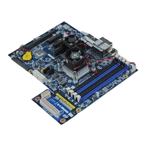
System Setup and Installation System Setup and Installation Power-On Kit Part Inventory 3.1.1 Customer Reference Board (CRB) Figure 2. Customer Reference Board 3.1.2 ATX Power Connector Figure 3. ATX Power Connector Getting Started Guide... -
Page 21: Chassis
System Setup and Installation 3.1.3 Chassis The provided Mohon Peak chassis. Figure 4. Chassis 3.1.4 Memory Two 2 GB UDIMMs will be included with every Mohon Peak Power-On Kit. Figure 5. 2 x 2 GB UDIMMs Getting Started Guide... -
Page 22: Mpi Socket
System Setup and Installation 3.1.5 MPI Socket Figure 6. MPI Socket Initial Board Setup 3.2.1 Building of MPI Socket Proper installation of the MPI socket and SoC processor are very important for the successful setup or upgrade of the Mohon Peak CRB. See step-by-step instructions below. 3.2.2 Tools and Supplies Required Figure 7. -
Page 23: Mpi Socket Handling Instructions
System Setup and Installation 3.2.3 MPI Socket handling Instructions Figure 8. MPI Socket handling instructions 3.2.4 MPI Socket Installation Assemble the C2xx0 or C2xx8 Bolster Plate on the secondary side of the PCB using four bolster plate screws. Align the pin on indicator on the bolster plate with pin one on the PCB. -
Page 24: Figure 10. Pcb Diagram
System Setup and Installation Place the C2xx0 or C2xx8 MPI socket on the PCB with pin one in the proper location and with the alignment pins in the alignment holes. Figure 10. PCB Diagram Figure 11. Pin-1 Alignment Diagrams Processor Package Placement Place the C2xx0 or C2xx8 package into the socket. -
Page 25: Figure 12. Processor Package Placement Diagrams
System Setup and Installation Figure 12. Processor Package Placement Diagrams Top Plate and CPU Fan Placement: Place the top Plate Assembly on top of the Package with the notch aligned with pin1. Lightly tighten each of the Barrel nuts until each Barrel nut has engaged with the plungers. -
Page 26: Placement Of The Board In The Chassis
System Setup and Installation 3.2.5 Placement of the Board in the Chassis Figure 15. Placement of Board in Chassis 3.2.6 Proper UDIMM Placement The UDIMM installation on the board is important for the BIOS and OS recognition of populated UDIMMs and proper functioning of the memory on the system. The first two UDIMMs to be installed on the CRB must properly terminate each memory channel on the CRB. -
Page 27: Correct Connection Of Atx Power Connector
System Setup and Installation 3.2.7 Correct Connection of ATX Power Connector The correct installation of the ATX Power connector is on the bottom right-side of the CRB. Do NOT connect the power connector to any other port on the board. Any other application of the power connector will OVER-LOAD the signal circuits permanently disabling the CRB. - Page 28 ® network ports on the board inoperable and may require return of the CRB to Intel for repair. Currently, the software tool used is called "eeupdate64E.EFI" and the process is as follows...
-
Page 29: Clearing Cmos
System Setup and Installation Once the steps above are complete, power the Mohon Peak system off, and remove the USB Flash drive. The system is now up to date and ready to use. Clearing CMOS Clearing the CMOS resets only the variables saved in the RTC registers. To clear the CMOS on a Mohon Peak CRB, the board must be powered off completely. -
Page 30: Customer Reference Board (Crb) Features
This document is intended as a guide for users of the Mohon Peak customer reference board (CRB). The Mohon Peak CRB is intended for customer reference and validation of the Intel® Atom® Processor C2000 Product Family for Microserver or the Intel® Atom® Processor C2000 Product Family for Communications Infrastructure System-on-a-Chip (SoC). -
Page 31: Cpu
Customer Reference Board (CRB) Features Figure 19. Mohon Peak CRB Component Diagram Figure 20. Mohon Peak Rear Panel Connectors 4.2.1 The SoC is based on the Silvermont, two-way superscalar, out-of-order IA core. The Silvermont is a 22 nm core used for ultra-low-power applications. The SoC can contain up to 8 Silvermont cores;... -
Page 32: Soc Sata Controllers
Customer Reference Board (CRB) Features • Various C-States (C0 through C6) The processor does not support Hyper-Threading (HT). 4.2.2 SoC SATA Controllers The SoC has two independent integrated SATA host controllers. The SATA2 controller supports Direct Memory Access (DMA) operation up to four ports and supports data transfer rates of 3.0 Gb/s (300 MB/s) and 1.5 Gb/s (150 MB/s). -
Page 33: Figure 21. Spi_Emul Header Pinout
Customer Reference Board (CRB) Features • BIOS1 (socketed) • BIOS2 (soldered onto the board) Two jumpers control the functioning of the BIOS Flash devices: • JP4 selects the active device (BIOS1 or BIOS2) • JP22 enables the SPI_EMUL header exclusive access to the selected Flash device for programming via the SPI bus. -
Page 34: Usb
Customer Reference Board (CRB) Features 4.2.4 Four USB 2.0 ports are supported on the Mohon Peak CRB. Two route to the back facing panel and two route either to a front-panel connector or to a MUXed Baseboard Management Connection (BMC). The F_USB front panel header is located adjacent to the SATA connectors, denoted by a nine pin header with a yellow base (see Figure 19). -
Page 35: Pcie* Slots
For more information on the use and function of this connector, please refer to page 53 in the Intel® Atom® Processor C2000 Product Family - Mohon Peak A2 Customer Reference Board Schematic, Revision 1.0 (CDI document number 506415). -
Page 36: Front Panel Connector
Customer Reference Board (CRB) Features Figure 23. Mohon Peak CRB Diagram - Trusted Platform Module Supported on LPC Bus 4.2.11 Front Panel Connector The Front Panel header allows for connection of chassis LEDs and buttons. This header is labeled "F_PANEL" and is in the lower left corner of the CRB. Figure 24. -
Page 37: Serial Port Drivers
Customer Reference Board (CRB) Features Serial Port Drivers From a Windows* client machine (for instance, a work laptop), install the serial port drivers, located at the following address: http://www.silabs.com/Support%20Documents/Software/ CP210x_VCP_Windows.zip Save and run the driver install file. Follow the on-screen prompts to install the driver. Obtain a mini-USB cable (USB Mini B). -
Page 38: Board Jumper Selection
Board Jumper Selection Board Jumper Selection Table 8 shows the Mohon Peak Jumpers. Table 8. Mohon Peak Jumpers Jumper MPK Usage Options Default HOST SMBus For Debug No Jumper Sensor SMBus For Debug No Jumper PECI SMBus For Debug No Jumper JP12 CMOS Clear [1-2]: Normal Operation... -
Page 39: Figure 25. Mohon Peak Jumper Selection Diagram (Upper Left Corner)
Board Jumper Selection Figure 25. Mohon Peak Jumper Selection Diagram (Upper Left Corner) Figure 26. Mohon Peak Jumper Selection Diagram (Lower Left Corner) Getting Started Guide... -
Page 40: Figure 27. Mohon Peak Jumper Selection Diagram (Lower Right Corner)
Board Jumper Selection Figure 27. Mohon Peak Jumper Selection Diagram (Lower Right Corner) Figure 28. Mohon Peak Jumper Selection Diagram (Upper Right Corner) § Getting Started Guide... - Page 41 Part 2: Yocto* This section contains the following chapter: Installing, Building, and Running Yocto* • § Document Number: 333035-003...
-
Page 42: Installing, Building, And Running Yocto
Consult the Intel® Atom® Processor C2000 Product Family for Communications Infrastructure Software for Linux* Release Notes (document 330683, “Board Support Package” section) to find the applicable package versions for Intel® QuickAssist Technology software, Intel® DPDK, Gigabit Ethernet driver, libcrypto*, netkey*, and Yocto* BSP packages. - Page 43 # git clone -b dylan http://git.yoctoproject.org/git/poky # cd poky Check out using the following poky/dylan commit ID: # git checkout d734ab491a30078d43dee5440c03acce2d251425 Extract the meta-intel tarball to the poky directory using the commands: # cd ~/poky # tar xjvf <path-to>/meta-mohonpeak-<version>.tar.bz2 # cd meta-mohonpeak-<version>...
- Page 44 This can shorten the build time when rerunning the bitbake command below. Edit the file ~/poky/build/conf/bblayers.conf to add meta-intel and meta- mohonpeak to the targets. Before the edit, the applicable lines will be the same as or similar to the following: BBLAYERS ?= "...
- Page 45 Remove all of the above packages added to MACHINE_EXTRA_RECOMMENDS MACHINE_EXTRA_RRECOMMENDS += "" In this way, it is ensured that the Yocto* build process will not try to locate and build Intel® DPDK or Intel® QuickAssist Technology related packages. Optional: To build the disk image with a newer version of the GbE driver (when available), modify the ~/poky/meta-intel/meta-mohonpeak/recipes-igb/igb/ igb.bb file to...
-
Page 46: Creating The Linux* Boot Disk
Installing, Building, and Running Yocto* Note: Please note the following: If there are build errors that appears to be script errors such as the one shown in the − following example, verify that is linked to as described in /bin/sh /bin/bash step [: 128: cmdline: unexpected operator |... -
Page 47: Creating A Sata Boot Disk
Installing, Building, and Running Yocto* Caution: The following commands assume that your flash drive is /dev/sdf. Modify the commands if necessary. Failure to use the correct path for the target drive may result in loss of data. Clone the image into the flash drive as follows: # sudo dd if=/dev/zero of=/dev/sdb bs=1M count=512 # sudo sync # sudo dd if=<path_to>/<image_name>.hddimg of=/dev/sdf... -
Page 48: Updating Eeprom Image
Installing, Building, and Running Yocto* Unmount the devices: # umount /tmp/Yocto-image # umount /tmp/Yocto-hdd Updating EEPROM Image The EEPROM image may need to be updated to the current version, which is available in the EDK (see document 516867). Section 7.5, “Updating EEPROM Image” includes instructions to update the EEPROM. -
Page 49: Intel® Quickassist Technology
Installing, Building, and Running Yocto* Prior to installing Intel® QuickAssist Technology software, the following steps are required. This step also ensures that SDK toolchain is properly installed. # cd /usr/src/kernel # make scripts # ln -s /usr/src/kernel /lib/modules/3.4.18-yocto-standard/build Note: See Section 1.2, “Where to Find Current Software and Documentation”... - Page 50 Part 3: Running on Fedora* This section contains the following chapters: • Installing and Setting Up Fedora* • Building and Installing the Software § Document Number: 333035-003...
-
Page 51: Installing And Setting Up Fedora
Installing and Setting Up Fedora* Acquiring Fedora* Fedora* 17 is a Linux* distribution built on free and open source software. The Intel® Atom® Processor C2000 Product Family for Communications Infrastructure Software for Linux* package does not include a distribution of Fedora* or any other Linux* variant. The package ®... - Page 52 On the Mohon Peak CRB system, use a different video card than the one provided by ® Intel ® Install the operating system using another Intel Architecture-based development system that supports the graphical installation, or Install the graphical desktop after the operating system has been installed. For details, Section 7.3.1, “Working Around Linux* Boot...
-
Page 53: Working Around Linux* Boot Errors
Note: If the system does not begin rebooting within 60 seconds, power cycle the board or press the reset button on the board and continue. ® Due to compatibility issues between the video card supplied by Intel and some recent Linux* distributions, the operating system may not load correctly. If this is the case, see Section 7.3.1... - Page 54 Installing and Setting Up Fedora* Note: The onboard GbE ports may not be functional until the steps in Section 7.6 have been completed. Install X-windows and the GNOME Desktop Environment: # yum -y groupinstall "X Window System" # yum -y groupinstall "GNOME Desktop Environment" # mv /etc/systemd/system/default.target /etc/systemd/system/default.target.org # ln -s /lib/systemd/system/graphical.target /etc/systemd/system/...
-
Page 55: Repairing The Monitor Configuration File
Installing and Setting Up Fedora* 7.3.1.3 Repairing the Monitor Configuration File Some versions of Linux* will crash or fail to boot when loading the default graphics driver with the graphical desktop. One workaround to this issue is to use the vesa driver instead of the ast driver. -
Page 56: Network Connectivity On Corporate Network
Extract the package. The EEPROM images are located in the \EEPROMS directory. Download the Intel® Network Connections Tools (formerly codenamed Quartzville) from the EDK, see document 348742. Extract the Intel® Network Connections Tool package and change to the correct directory: Getting Started Guide... -
Page 57: Installing The 4X 1Gbe Network Driver
Restart the system using the following command: # shutdown -r now Installing the 4x 1GbE Network Driver If required, install the 1 GbE Network driver; see "Intel® Ethernet Drivers and Utilities" in Section 1.2.1, “Accessing Content from the Open Source Technology Centre”. Following the instructions in Section 1.2, download the Networking Software Drivers for... - Page 58 Installing and Setting Up Fedora* # cd igb-<version> # cd src Build and install the driver: # make # make install Load the driver: # modprobe igb Restart network stack: # service NetworkManager restart Verify that the 4x 1GbE network ports are visible using ifconfig. Verify that these network ports can obtain an IP address and pass traffic.
-
Page 59: System Security Considerations
System Security Considerations System Security Considerations This section contains a high-level list of system security topics. Specific OS/filesystem topics are outside of the scope of this document. For more information, see the Rangeley Software Programmer’s Guide, specifically the Secure Architecture Considerations section. Securing your operating system is critical. -
Page 60: Building And Installing The Software
This chapter provides details on building and installing the software on the development kit. Unpacking the Software The software package comes in the form of a tarball. See If required, install the 1 GbE Network driver, see "Intel® QuickAssist Technology Drivers and Patches" in Section 1.2.1, “Accessing Content from the Open Source Technology Centre”. -
Page 61: Installerlog
Building and Installing the Software # ./installer.sh A welcome message is displayed, followed by Installation Options. The table below lists the available installation options. Note: If you have not unpacked the release package tarball as described in Section 9.1, errors will be returned. -
Page 62: Installation On A New Development Platform
• sriov_options: host / guest • service_options: build_sample / build_dc_only / gige • path: Location where you would like to build the Intel® QuickAssist Technology package Note: Do not combine action and service options, and be sure to start your path with / Example usage: •... -
Page 63: Cross-Compilation Capabilities For Intel® Quickassist Technology
Cross-Compilation Capabilities for Intel® QuickAssist Technology These capabilities enable users to compile the Intel® QuickAssist Technology driver on one system for the targeted architecture of another system. Note: The following instructions are valid for Fedora*. Steps for Yocto* will be included in a future revision. - Page 64 Here’s a sample output for a non-mux build (see Section 1.5.3 for file names in mux build cases): adf_ctl: ELF 32-bit LSB executable, Intel 80386, version 1 (SYSV), dynamically linked (uses shared libs), for GNU/Linux 2.6.32, not stripped c2xxx_qa_dev0.conf: ASCII English text dh89xxcc_qa_dev0.conf: ASCII English text...
-
Page 65: Starting/Stopping The Acceleration Software
Configuration Files When the Acceleration software loads, it is configured based on settings in the configuration file (c2xxx_qa_dev0.conf). The configuration file is placed in the /etc directory. For example, the configuration files for the Intel® Atom® Processor C2000 Getting Started Guide... -
Page 66: Minimizing Acceleration Software Compilation Time
Building and Installing the Software Product Family for Communications Infrastructure devices are: c2xxx_qa_dev0.conf and c2xxx_qa_dev0_single_ae.conf. The c2xxx_qa_dev0_single_ae.conf file is intended for use with SKUs that contain a single acceleration engine. The files are processed when the system boots. If changes are made to the configuration file, the Acceleration software must be restarted for the changes to take effect. - Page 67 Part 4: Running Sample Applications This section contains the following chapter: • Running Sample Applications § Document Number: 333035-003...
-
Page 68: Running Sample Applications
This section describes the sample code that can be executed on the target platform along with instructions on their usage for both Yocto* and Fedora*. 10.1 Intel® QuickAssist Technology Acceleration Sample Application The software package contains a set of sample tests that exercises the SoC acceleration functionality. -
Page 69: Loading The Sample Code
Running Sample Applications You may be prompted for a directory location to build the package and the Build Output Directory. Use the default value for the location to build the package. The Build Output Directory parameter is ignored. Note: In the case where both QAT1.5 and QAT1.6 drivers are loaded, the sample code from the QAT1.6 driver should be used. -
Page 70: Signoflife Tests
Running Sample Applications The lsmod command verifies the kernel driver is installed. The qat_service command reports the status of the device. Typical output is: There is 1 acceleration device(s) in the system: icp_dev0 - type=c2XXX, inst_id=0, bsf=00:0b:0, #accel=1, #engines=2, state=up Note: If the module is not returned from the first command, refer to Section 9.5, “Starting/Stopping the Acceleration Software”... -
Page 71: Wireless Tests
Running Sample Applications Note: If the signOfLife parameter is not specified, the full run of tests can take several hours to complete. In addition, for RSA 4096 and DH 4096 tests, there can be up to an hour with no perceived result activity. -
Page 72: Test Results
Running Sample Applications The software package includes a version of the firmware optimized for small cryptography packets. In order to run the sample code with this firmware, the following steps must be performed. An example configuration file is included in the package. # cp $ICP_ROOT/quickassist/config/c2xxx_qa_dev0.conf.v1.wireless /etc/ c2xxx_qa_dev0.conf Restart the acceleration service using the command:... -
Page 73: Unloading The Sample Code
Running Sample Applications A similar pattern is repeated for each of the tests. Note: The sample code will log the error messages shown below. They can be safely ignored, as the SoC does not support data compression. main():1041 Unable to Get Number of DC instances Sample Code Complete 10.1.4 Unloading the Sample Code... -
Page 74: Executing The Acceleration Functional Sample Code In Kernel Space
Executing the Acceleration Functional Sample Code in User Space To execute the acceleration functional sample code in User Space, the kernel memory driver qaeMemDrv.ko must be installed. See Section 10.1, “Intel® QuickAssist Technology Acceleration Sample Application” for information on compiling the performance sample code. - Page 75 Running Sample Applications Note: nrbg_sample is one of the functional user space applications. You can launch the other user space applications in a similar fashion. § Getting Started Guide...
-
Page 76: Appendix A Intel® Atom® Processor C2000 Product Family Bios Post/Error Codes
Intel® Atom® Processor C2000 Product Family BIOS Post/Error Codes Intel® Atom® Processor C2000 Product Family BIOS Post/Error Codes Post Codes A.1.1 SEC Phase Table 11. SEC Phase Post Code Description 0x01 BSP Protected Mode Start 0x02 Status_Code 0x03 Platform Initialization – Microcode Loaded... -
Page 77: Memory Reference Codes (Mrc) Post Codes
Intel® Atom® Processor C2000 Product Family BIOS Post/Error Codes Memory Reference Codes (MRC) Post Codes Table 13. MRC Post Codes Post Code Description 0x10 Enable HPET 0x11 Update Variables 0x12 Enable Clock Gating 0x13 Clear Self Refresh 0x14 Oem Track Init Complete... - Page 78 Intel® Atom® Processor C2000 Product Family BIOS Post/Error Codes Post Code Description 0x92 Set DDR Initialization Complete 0xB0 Handle Rank Overrides… Rank to rank switching enabled 0xB1 Enable Diffamp And Odt Overrides 0xB2 Early Set Write Vref… Vref Set: 0x40...
-
Page 79: Mrc Error Codes
Intel® Atom® Processor C2000 Product Family BIOS Post/Error Codes MRC Error Codes Table 14. MRC Error Codes Error Code Description 0xE7 Frequency requested by Dimm or user not supported 0xE8 No memory detected 0xE9 Risers from two different platform mixed, 2SPC\3SPC risers are mixed... -
Page 80: Appendix Bbios Update Using An Spi Programmer
BIOS Update Using an SPI Programmer BIOS Update Using an SPI Programmer This section provides details for programming the Flash memory containing the BIOS on the Mohon Peak CRB. The following example was performed using a laptop running Windows* 7 Enterprise* installed, using an in-circuit SPI Flash programmer (DediProg* SF600). -
Page 81: Software Required
BIOS Update Using an SPI Programmer Figure 29. DediProg SF600 Programmer and Adapter Software Required Download and install the SF600 installation software on the Windows* PC (this example uses SF6.0.4.04.zip). http://www.dediprog.com/download/ Setup Plug the programming cable into the SO connection adapter, making sure to align the striped edge of the cable with pin 1 of the connector. -
Page 82: Programming
BIOS Update Using an SPI Programmer Figure 30. DediProg SF600 Connected to the Mohon Peak CRB Programming With the SF600 programmer connected as described in Section B.3, plug the system (ATX) power supply in and turn the power supply on. Do not push the power button on the CRB, or the front panel of the chassis (SPI Flash must be programmed with standby power from the system power supply, but without the CRB actually running.) -
Page 83: Figure 32. Dediprog Memory Type Selection
BIOS Update Using an SPI Programmer Select M25P64 in the Memory Type pop-up window and then click OK. Figure 32. DediProg Memory Type Selection In the main DediProg Software window that appears, click the File icon in the tool bar at the top, and select the BIOS firmware file in the selector pop-up window. -
Page 84: Appendix Cbios Update Using Bootable Software
BIOS Update Using an SPI Programmer Click the Erase icon in the tool bar to reset the contents of Flash memory for programming. Figure 34. DediProg Erase Flash Click the Prog icon in the tool bar to actually put the BIOS into Flash. Figure 35. - Page 85 BIOS Update Using an SPI Programmer Turn the power to the Mohon Peak CRB off. Exit the DediProg software on the PC, disconnect the SF600 programmer from the Mohon Peak CRB, and change jumper JP22 to connect pins 1-2. Power the board on to configure and use the new BIOS. §...
- Page 86 7. Move JP4 to select the desired Flash part to program. Leave JP22 set to connect pins 1-2. ® Download the Flash Programming Tool from the Intel Business Portal.. Unzip the package and copy the files below to the root directory of a USB Flash drive.
Need help?
Do you have a question about the Atom C2000 and is the answer not in the manual?
Questions and answers