
Related Manuals for Thermo Scientific 700 Series


Summary of Contents for Thermo Scientific 700 Series
- Page 1 Model 700 Series Forma -86C ULT Freezer Operating and Maintenance Manual 7020702 Rev. 7...
- Page 2 23156 2/8/06 Changed 8656-90 refrigeration schematic 22930 2/8/06 WEEE directive 22962 10/28/05 Changed strain relief 22895 8/11/05 Removed rotalok valves from compressors 7/14/05 Release 3 HVRP door mounted ECR/ECN DATE DESCRIPTION Thermo Fisher Scientific Thermo Fisher Scientific Model 700 Series...
- Page 3 In no event shall Thermo be held liable for any damages, direct or incidental, arising out of or related to the use of this manual. ©2005 Thermo Fisher Scientific. All rights reserved. Model 700 Series Thermo Fisher Scientific Thermo Fisher Scientific...
- Page 4 Always use the proper protective equipment (clothing, gloves, goggles, etc.) ✔ Always dissipate extreme cold or heat and wear protective clothing. ✔ Always follow good hygiene practices. ✔ Each individual is responsible for his or her own safety. Thermo Fisher Scientific Thermo Fisher Scientific Model 700 Series...
- Page 5 If you wish to write, our mailing address is: Thermo Fisher Scientific Inc Controlled Environment Equipment 401 Millcreek Road, Box 649 Marietta, OH 45750 International customers, please contact your local Thermo distributor. Model 700 Series Thermo Fisher Scientific Thermo Fisher Scientific...
-
Page 6: Table Of Contents
Preventive Maintenance ........4-7 Thermo Fisher Scientific Model 700 Series... - Page 7 Electrical Schematics ........9-1 Section 9 Warranty Appendix Declarations of Conformity Model 700 Series Thermo Fisher Scientific...
-
Page 8: Installation And Start-Up
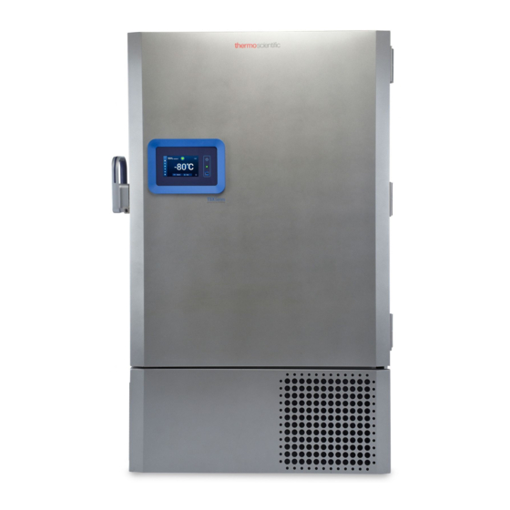
Figure 1-1. Front View Figure 1-2 • Remote alarm contacts. • Power Inlet for power cord connection. • Optional BUS connections for probe and solenoid. • Power Switch (mains disconnect). Figure 1-2. Rear View Thermo Fisher Scientific Model 700 Series... - Page 9 • Freezer filter location Figure 1-4. Vacuum Relief and Probe Cover Location Battery power switch remove filter Thermocouple receptacle Battery mounting bracket Freezer battery and optional BUS battery Figure 1-5. Battery(s) Location and Switch Model 700 Series Thermo Fisher Scientific...
-
Page 10: Control Panel Keys, Displays/Indicators
• Enter - Stores the value into memory. Keypad Operation The Model 700 Series freezer has five basic modes which allow freezer setup and operation. Press the Mode key to scroll through the mode selections. Up Arrow: Increases or toggles the parameter value. -
Page 11: Install Freezer
Cap Protector Install the bolts into the pre-tapped holes on the back of the compressor section. Install a neoprene cap on each bolt. Refer to Figure 1-2 for the locations of the pre-tapped holes. Model 700 Series Thermo Fisher Scientific... -
Page 12: Install The Shelves
Figure 1-8. Remote Alarm Contacts Attach the Power Cord Insert the power cord into the power inlet module. Place the retaining bracket (P/N 195763) over the connector. Tighten retaining screws to secure. Figure 1-9. Power Cord Connection Thermo Fisher Scientific Model 700 Series... -
Page 13: Connect The Unit To Electrical Power
Caution If the set point is changed and the low temperature and high temperature alarms are set 10° from the set point, the alarm set points will adjust automatically to maintain a distance of at least 10° from set point. ▲ Model 700 Series Thermo Fisher Scientific... -
Page 14: Set The Operating Temperature
Section 1 Installation and Start-Up Set the Operating All Model 700 Series freezers have an operating temperature range of - 50°C to -86°C, depending on ambient temperature. The freezer is shipped Temperature from the factory with a temperature set point of -80°C. To change the operating temperature set point: 1. -
Page 15: Set The Low Temperature Alarm
In addition, Run mode allows display of the high stage heat exchange temperature. This information is scrolled by pressing the up or down arrow keys. The display will return to the operating temperature in 10 seconds if no keys are pressed. Model 700 Series Thermo Fisher Scientific... -
Page 16: Calibrate
Note During calibration, the temperature display is not available. ▲ If no keys are pressed for approximately five minutes while in Calibrate mode, the system will reset to Run mode. Thermo Fisher Scientific Model 700 Series... -
Page 18: Alarms
Alarms Section 3 The Model 700 Series freezer alarms are displayed on the freezer control panel. When an alarm is active, the indicator next to the alarm description lights and an audible alarm sounds. Press the Silence key to disable the audible alarm for the ringback period. -
Page 19: High Stage System Failure
The audible alarm can be silenced and will ringback every 15 minutes. Probe Failure Alarm The microprocessor in Model 700 Series freezers continually scans all probes including the control probe, heat exchanger probe and condenser probe to ensure that they are operating properly. Should an error be detected, the "Probe Failure"... -
Page 20: Maintenance
Figure 1-5. (minimum yearly) 2. Using a vacuum cleaner and being very careful not to damage the condenser fins, clean the condenser. Depending upon environmental conditions, the condenser may need to be cleaned more frequently. Thermo Fisher Scientific Model 700 Series... -
Page 21: Clean Water-Cooled Condenser
8. Add and circulate a passivating liquid for corrosion inhibition of plate surfaces. 9. Drain this liquid. 10. Rinse with fresh water and drain. 11. Reconnect the water supply and fill the unit. 12. Return to service. Model 700 Series Thermo Fisher Scientific... -
Page 22: Defrost The Chamber
The unit is designed with a “vacuum relief port” that allows the pressure to be equalized. Thermo Fisher Scientific Model 700 Series... - Page 23 Caution Do not leave the freezer unattended while the door is unlatched. The vacuum could release, resulting in a door opening and the potential for product loss. ▲ Figure 4-2. Insert Tool Figure 4-3. Detail Model 700 Series Thermo Fisher Scientific...
-
Page 24: Replace The Battery(S)
Defrost the unit as described previously. This prepares the unit for storage. Turn off the battery power switch (O). Turn off the freezer power switch. Storage Disconnect power to the battery(s) and to the freezer. Thermo Fisher Scientific Model 700 Series... -
Page 25: Preventive Maintenance
PREVENTIVE MAINTENANCE Freezers Your equipment has been thoroughly tested and calibrated before shipment. Regular preventive maintenance is important to keep your unit functioning properly. The operator should perform routine cleaning and maintenance on a regular basis. For maximum performance and efficiency, it is recommended that the unit be checked and calibrated periodically by a qualified service technician. - Page 26 Preventive Maintenance for 700 Series Freezers Refer to Manual Section Action Monthly Yearly Every 2 Years Verify ambient temperature, <90°F * Adjust door handle for firm latching, as needed Figure 1-4 for probe location Check and clean probe cover, gaskets, hinges, inner doors...
-
Page 28: Factory Installed Options
1/8” NPT brass tee on the open end of the nipple. Place Permagum sealant between the brass tee and the interior top. 5. Remove the two Phillips head screws securing the metal bracket on the vent stack assembly. Thermo Fisher Scientific Model 700 Series... - Page 29 The solenoid mounting bracket is not required and may be discarded. Caution When selecting a CO supply cylinder, it must be equipped with a siphon tube. ▲ Figure 5-1. Injection Assembly Figure 5-2. Vent Stack Model 700 Series Thermo Fisher Scientific...
-
Page 30: Install The Temperature Probe
3. Tap #8-32 the two pre-punched holes located on the interior left wall of the freezer. Mount the bracket. Figure 5-4 shows the Back-Up probe mounted on the interior left side wall of the freezer. Figure 5-4. Probe Bracket Location Thermo Fisher Scientific Model 700 Series... -
Page 31: Connect The Probe/Solenoid Harness
5. Turn the battery switch to Standby mode ( ) to charge both batteries. Tie wrap anchor Probe wire Spade lug BUS connection connections to solenoid RS-232 or RS-485 Interface Power switch (mains disconnect) Remote alarm contacts and Power Inlet analog output Figure 5-5. Routing Model 700 Series Thermo Fisher Scientific... -
Page 32: Bus Operation And Maintenance
3. Press Enter to save the setting. 4. Press the Mode key until the Run indicator lights for Run mode. If no control keys are pressed, the freezer will automatically return to Run mode after 5 minutes. Thermo Fisher Scientific Model 700 Series... -
Page 33: Set The Optional Bus Set Point
2. Depress the test button on the BUS control box to remove the gas from the line. 3. Slowly disconnect the fitting assembly from the supply (in the event that any gas remains in the line). Model 700 Series Thermo Fisher Scientific... -
Page 34: Chart Recorder
5. When the desired program number is 50°C flashing, press button #3 to bring the pen 100°C arm back onto the chart. Recording will -100 200°C begin in the new program. -115 50°C 70°C Thermo Fisher Scientific Model 700 Series... -
Page 35: Calibrate The Chart Recorder
PC. A variety of statistical information is provided through calculations, analysis, graphs and printed reports. Refer to the ELPRO documentation for operating instructions for the datalogger. Model 700 Series Thermo Fisher Scientific... -
Page 36: Water-Cooled Condenser
The five inner door option (P/N 189405, 189406, 189407, 195642) is factory installed. The freezer is converted to accommodate four Option adjustable specimen shelves with the fifth “shelf ” as the bottom of the freezer chamber. Thermo Fisher Scientific Model 700 Series... -
Page 38: Specifications
Time Delay Breaker Time Delay Breaker Shipping Weight: 712 lbs. (323.0 kg) 712 lbs. (323.0 kg) 795 lbs. (360.6 kg) Motor *Compressors may not cycle off with cabinet running at -86C in a 32C ambient. Thermo Fisher Scientific Model 700 Series... - Page 39 Time Delay Breaker Time Delay Breaker Shipping Weight: 795 lbs. (360.6 kg) 900 lbs. (408.2 kg) 900 lbs. (408.2 kg) Motor *Compressors may not cycle off with cabinet running at -86C in a 32C ambient. Model 700 Series Thermo Fisher Scientific...
- Page 40 Pollution degree describes the amount of conductive pollution present in the operating environment. Pollution degree 2 assumes that normally only non-conductive pollution such as dust occurs with the exception of occasional conductivity caused by condensation. Thermo Fisher Scientific Model 700 Series...
- Page 42 Thermo Fisher Scientific Model 700 Series...
- Page 43 Model 700 Series Thermo Fisher Scientific...
- Page 44 Thermo Fisher Scientific Model 700 Series...
- Page 45 Door Assembly Model: 700 Series ULT Upright Freezer 702-201-1-B Rev. 3 Page 1 of 2 Model 700 Series Thermo Fisher Scientific...
- Page 46 Door Assembly Model: 700 Series ULT Upright Freezer 702-201-1-B Rev. 3 Page 2 of 2 Thermo Fisher Scientific Model 700 Series...
- Page 49 Part Number 230 Volt Relay Enclosure Assembly 8602-204-1-B Rev . 4 Quantity Page 1 of 2 Model 700 Series Thermo Fisher Scientific...
- Page 50 230 Volt Relay Enclosure Assembly 8602-204-1-B Rev . 4 Page 2 of 2 Thermo Fisher Scientific Model 700 Series...
- Page 51 Part Number 120 Volt Relay Enclosure Assembly 8602-204-2-B Rev . 4 Quantity Page 1 of 2 7-10 Model 700 Series Thermo Fisher Scientific...
- Page 52 120 Volt Relay Enclosure Assembly 8602-204-2-B Rev . 4 Page 2 of 2 Thermo Fisher Scientific Model 700 Series 7-11...
- Page 62 Thermo Fisher Scientific Model 700 Series...
- Page 63 Model 700 Series Thermo Fisher Scientific...
- Page 64 Thermo Fisher Scientific Model 700 Series...
- Page 66 Model 700 Series Thermo Fisher Scientific...
- Page 67 Thermo Fisher Scientific Model 700 Series...
- Page 68 Model 700 Series Thermo Fisher Scientific...
- Page 70 Thermo Fisher Scientific Model 700 Series 10-1...
- Page 71 10-2 Model 700 Series Thermo Fisher Scientific...
- Page 72 Be sure to follow instructions supplied with the withdrawal device. When liquid cylinders or other large storage con- tainers are used for filling, follow the instructions supplied with those units and their accessories. Thermo Fisher Scientific Model 700 Series...
- Page 73 Disposal of liquid nitrogen should be done outdoors in a safe place. Pour the liquid slowly on gravel or bare earth where it can evaporate without causing damage. Do not pour the liquid on pavement. Model 700 Series Thermo Fisher Scientific...
- Page 74 Disposal of liquid CO should be done outdoors in a safe place. Pour the liquid slowly on gravel or bare earth where it can evaporate without causing damage. Do not pour the liquid on pavement. Thermo Fisher Scientific Model 700 Series...
- Page 76 Model 700 Series Thermo Fisher Scientific...
- Page 77 Thermo Fisher Scientific Model 700 Series...
- Page 78 Thermo Fisher Scientific Controlled Environment Equipment 401 Millcreek Road Marietta, Ohio 45750 United States www.thermofisher.com...
Need help?
Do you have a question about the 700 Series and is the answer not in the manual?
Questions and answers