
Related Manuals for Emerson Rosemount CT4215


Summary of Contents for Emerson Rosemount CT4215
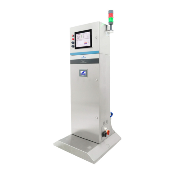
- Page 1 Reference Manual 00809-0100-4245, Rev AC July 2022 ™ Rosemount CT4215 Leak Detection System...
- Page 2 Preface Published by Emerson. All possible care has been taken in the preparation of this publication, but Emerson and its agents and distributors accept no liability for any inaccuracies that may be found. Emerson reserves the right to make changes without notice both to this publication and the products which it describes.
- Page 3 All users must read this page before proceeding! Emerson designs, manufactures, and tests its products to meet national and international standards. To ensure the product, continues to operate as designed and within normal specifications, it MUST be installed, used, and maintained correctly.
- Page 4 General safety notice/residual risk Installation, operation, and maintenance of the leak detection system must be in accordance with these instructions. Authorized personnel Personnel installing, operating, servicing, and maintaining the leak detection system must be instructed, trained and qualified with the operating company and the manufacturer. It is the operating company's responsibility to: •...
- Page 5 This product is designed and manufactured under an approved quality management system to ISO 9001: 2015. Emerson have satisfied the requirements for applying the CE and UKCA marking to this product. This equipment meets all requirements of the EMC and Low Voltage directives.
- Page 6 Hazard messages This document uses the following criteria for hazard messages based on ANSI standards Z535.6-2011 (R2017). DANGER Serious injury or death will occur if a hazardous situation is not avoided. WARNING Serious injury or death could occur if a hazardous situation is not avoided. CAUTION Minor or moderate injury will or could occur if a hazardous situation is not avoided.
- Page 7 WARNING HEAVY ITEM Serious injury or death could occur. The leak detection system weighs 119 kg (263 lb) and should only be moved by a minimum of two people using suitably rated lifting/moving equipment . To prevent crushing of hands, feet, or other body parts always wear suitable protective gloves and footwear when handling.
- Page 8 CAUTION LASER / OPTICAL PATH Minor or moderate injury will or could occur Operators do not have access to the internal laser or electrics during normal operation. Maintenance personnel must only access the internal laser or electrics after the analyzer has been turned off.
- Page 9 Safety and system labels and annotation Labels are applied to the analyzer in the positions shown below. Location Label Type Label fitted Identification label (including the Serial No. (S/N), Model No. and Date of Manufacture (DoM). AC Supply Voltage Chassis earth terminal location Laser radiation CAUTION label...
- Page 10 Location Label Type Label fitted Laser module identification label Fuse and circuit breaker identification label. Isolate before removing cover DANGER Label AC Supply Voltage Electrical safety label.
-
Page 11: Table Of Contents
Reference Manual Contents 00809-0100-4245 July 2022 Contents Chapter 1 Leak detection overview..................13 1.1 System overview........................13 Chapter 2 Equipment and accessories..................15 2.1 Upper and lower enclosures.......................15 2.2 Main operating controls and displays ..................16 2.3 Analysis cell and purge.......................17 2.4 Electrical back plate........................ - Page 12 Contents Reference Manual July 2022 00809-0100-4245 Rosemount CT4215...
-
Page 13: Leak Detection Overview
Reference Manual Leak detection overview 00809-0100-4245 July 2022 Leak detection overview The CT4215 Leak Detection System, hereafter referred to as CT4215 or the leak detector, is an electronic sensor that uses laser spectroscopy to identify gasses used in the food and beverage industries as product is carried along a conveyor belt at high speed. - Page 14 C. HMI touch screen. D. Status beacon. E. Product line direction. F. Input gate. G. Rejector. H. Sample head. I. Reject chute (Collection bin customer supplied). J. Circuit breakers. K. AC supply. L. Customer connections. M. Compressed air line connections. Rosemount CT4215...
-
Page 15: Equipment And Accessories
Reference Manual Equipment and accessories 00809-0100-4245 July 2022 Equipment and accessories Upper and lower enclosures A. Lower enclosure door with PLC control panel fitted. B. Upper enclosure door with HMI panel LED and reset buttons. C. Upper enclosure fitted with the analysis cell and cell purge. D. -
Page 16: Main Operating Controls And Displays
Equipment and accessories Reference Manual July 2022 00809-0100-4245 Main operating controls and displays A. USB port 2. B. USB port 1. C. Air fault indicator. D. Reset button. E. Main HMI display screen. F. PLC screen. Rosemount CT4215... -
Page 17: Analysis Cell And Purge
Reference Manual Equipment and accessories 00809-0100-4245 July 2022 Analysis cell and purge The assembly shown is mounted in the upper enclosure. A. Manual purge button. B. Gas sample inlet from the production line. C. Toggle clamp. D. Gas sample outlet connected to the blower motor. E. -
Page 18: Electrical Back Plate
Reference Manual July 2022 00809-0100-4245 Electrical back plate The assembly shown is mounted in the 1 compartment of the lower enclosure. A. Electronics panel. B. Electrical back plate upper DIN rail. C. Electrical back plate lower DIN rail. Rosemount CT4215... - Page 19 Reference Manual Equipment and accessories 00809-0100-4245 July 2022 Figure 2-1: Upper DIN rail components A. Earth terminal block. B. 6A MCB breaker. C. End stop. D. Terminals. E. 24V power supply. F. 12V power supply. G. PLC. Figure 2-2: Lower DIN rail components A.
-
Page 20: Air Preparation Plate
The assembly shown is A. Ethernet hub. B. Factory compressed air in. C. Shut off valve. D. Pressure regulator with 40 µm filter. E. 0.1 µm filter. F. Membrane dryer. G. Pressure switch (MPa). H. Filtered air out. I. Reject solenoid. Rosemount CT4215... -
Page 21: Blower And Electrical Shut Off
Reference Manual Equipment and accessories 00809-0100-4245 July 2022 Blower and electrical shut off The assembly shown is mounted in the 3 compartment of the lower enclosure. A. Sample gas blower motor. B. Cooling fans. C. Electrical shut off and isolation. D. -
Page 22: Leak Detector Interface Connections
D. Sample gas inlet connection to the cell. E. Sample gas outlet from the cell to the blower motor inlet. F. In line cartridge filter . G. Ø19mm inside diameter sample line connected to the sample head. Maximum tube length 5 metres. Rosemount CT4215... - Page 23 Reference Manual Equipment and accessories 00809-0100-4245 July 2022 Power, communication and compressed air connections. A. Mains On/Off isolator. B. Blower motor isolator. C. Blower status lamp indicating there is power to the blower motor. D. Mains electrical connection point. (Customer option, factory configured for 110VAC or 230VAC.
-
Page 24: Leak Detector Installed Examples
Examples of which are shown below. Further sampling or bespoke options can be discussed with your local Emerson distribution partners. Typical Beverage Production System Typical Food Production System A. -
Page 25: Sample Head Types
Reference Manual Equipment and accessories 00809-0100-4245 July 2022 Sample head types Sample heads are used in conjunction with the leak detector to identify packaged products that have a break in the seal integrity as they are carried along a conveyor belt at speed. - Page 26 The sample bar MUST be installed < 25 mm (1 inch) above the height of the keg/barrel being tested allowing the product to pass freely underneath the bar. If CO is leaking from around the valve on the keg/barrel it will be drawn into the sample bar and detected by the analyzer. Rosemount CT4215...
-
Page 27: Chapter 3 Installation
Reference Manual Installation 00809-0100-4245 July 2022 Installation Site selection Site selection for the leak detector MUST consider the following to ensure optimal performance. Environment The leak detector is for indoor use only. The leak detector MUST be installed in a dry location, protected from the elements, humidity, temperature variations and direct sunlight. - Page 28 Reference Manual July 2022 00809-0100-4245 All dimensions are in mm [inches]. A. Plan view showing floor area required for installation of the leak detector. B. Plan view showing floor area required for the leak detector with transportation wheels fitted. Rosemount CT4215...
-
Page 29: Unpacking
Reference Manual Installation 00809-0100-4245 July 2022 Unpacking WARNING HEAVY ITEM Serious injury or death could occur. The leak detection system weighs 119 kg (263 lb) and should only be moved by a minimum of two people using suitably rated lifting/moving equipment . To prevent crushing of hands, feet, or other body parts always wear suitable protective gloves and footwear when handling. - Page 30 The ramp can now be located at the front of the shipping container. Visually inspect the exterior of the analyzer for signs of damage and verify that all items shipped were received. Report anything found to the maintenance organization. Rosemount CT4215...
- Page 31 Reference Manual Installation 00809-0100-4245 July 2022 Remove the 4 x M10 nuts and washers securing the leak detector to the floor of the shipping container. Remove the threaded rod. from the container floor. Finally, remove any straps used to secure the leak detector upper sections from vibration during transit.
- Page 32 4 x Fork lift pockets are provided as part of the transportation trolleys. Care must be taken if a fork lift is used as there is limited head clearance between the shipping container and the top off the leak detector. Rosemount CT4215...
-
Page 33: Installing The Leak Detector
Reference Manual Installation 00809-0100-4245 July 2022 Installing the leak detector The location selected for the leak detector will be in accordance with the Site selection criteria. Free access to the connections on the rear of the leak detector will be required at all times. - Page 34 The location selected will need two holes drilled in the floor 636mm [25in] apart to suit M8 anchor bolts. This will secure the leak detector when installed. A Securing anchor bolt hole dimensions. B Leveling feet pads. C M8 Anchor bolt. D Additional oversized washer. Rosemount CT4215...
- Page 35 Reference Manual Installation 00809-0100-4245 July 2022 Once the leak detector has been moved into position the transportation wheels must be removed. Note There is limited clearance between the M8 bolt head and the floor as shown opposite. Remove the 8 off M8 bolts and washers securing the transportation wheels to the leak detector base.
- Page 36 The beacon has been fitted to the enclosure upside down for transportation. Using an 8mm AF hex allan key give a quarter turn to open the top enclosure door lock. Note Cables are connected to the inside of the door. Rosemount CT4215...
- Page 37 Reference Manual Installation 00809-0100-4245 July 2022 Remove the M4 fasteners used to the secure the beacon to the enclosure, rotate the beacon and refit the fasteners. Close and lock the enclosure door when complete. The hose from sample head can now be connected to the inlet filter fitted to the rear of the leak detector.
-
Page 38: Electrical, Signal, Compressed Air In And Sample Gas Connection Details
The voltage at the installation site must meet the rated voltage required. Procedure 1. All electrical /connections are fitted to the rear panel of the leak detector . 2. Power to the leak detector is connected through the Mains Power Inlet using the connector provided. Rosemount CT4215... - Page 39 Reference Manual Installation 00809-0100-4245 July 2022 A. Mains power connection. B. Power cable connector (supplied loose) C. Customer supplied power cable. (minimum required cable Specification will be defined by a competent Engineer or technician ensuring cable selection meets local standards for power demands for the cable length required. Item Designation Type...
- Page 40 Max rating Description Ethernet RJ45 Ethernet Communication with sensor. Status Bulgin 3P male 30Vdc, 1A Relay contacts to signal the system is running correctly. Status connection for customer telemetry output connection. Mating connector will be supplied with the unit. Rosemount CT4215...
- Page 41 Reference Manual Installation 00809-0100-4245 July 2022 Item Designation Type Max rating Description Reject Bulgin 3P female 24Vdc, 0.8A Signal to trigger the rejection solenoid when a defective pack is detected. Signal connection from the sample head reject gate. Mating connector will be supplied with the unit.
- Page 42 Factory compressed air in connected to the inlet on the air preparation plate. E. Optional compressed air out supplying an air reject system. 8mm outside diameter push fit plastic tubing. F. Sample gas exhaust from the blower motor. Rosemount CT4215...
-
Page 43: Start-Up Procedure
Reference Manual Start-up procedure 00809-0100-4245 July 2022 Start-up procedure WARNING HIGH PRESSURE AIR Serious injury or death could occur. The compressed air supply operate at pressures that can cause injury. CAUTION AIR SUPPLY Minor or moderate injury will or could occur Air provided must be connected from a pressure regulated clean, filtered and moisture free supply source. - Page 44 10. Switch on the factory compressed air supply. 11. Switch on the blower motor at the blower isolator switch mounted on the lower right panel, the blower status lamp should be on, if not report the fault to the maintenance organization. Rosemount CT4215...
- Page 45 Reference Manual Start-up procedure 00809-0100-4245 July 2022 It is recommended that the blower is switched off when the production line is not running. This will extend the lifetime of the sample air filter. 12. Press the Reset button and ensure there is a green light on the beacon to confirm the leak detector is now operational.
- Page 46 Start-up procedure Reference Manual July 2022 00809-0100-4245 Rosemount CT4215...
-
Page 47: Shut Down Procedure
Reference Manual Shut down procedure 00809-0100-4245 July 2022 Shut down procedure WARNING HIGH PRESSURE AIR Serious injury or death could occur. The compressed air supply operate at pressures that can cause injury. CAUTION AIR SUPPLY Minor or moderate injury will or could occur Air provided must be connected from a pressure regulated clean, filtered and moisture free supply source. - Page 48 5. Switch off the unit and blower isolators mounted on the side panel. 6. Mains voltage is still being applied to the leak detector. Turn off the mains power at the customer supplied circuit breaker or remove the plug. Rosemount CT4215...
-
Page 49: Software Interface Description
Reference Manual Software interface description 00809-0100-4245 July 2022 Software interface description The leak detector is designed to run with minimal user interaction required unless a fault is detected. Under normal operating conditions the green LED will be on to show everything is operating correctly, the red LED shows comes on when a fault has been detected. - Page 50 The plot shows all data points between the input and output gate and records the size of any rejection spike detected. 6.1.1 Setup Factory only configuration screen Rosemount CT4215...
- Page 51 Reference Manual Software interface description 00809-0100-4245 July 2022 6.1.2 View log Select View Log. This activates a log screen which shows various automated actions taken by the system software. Used in case of communications issue with the laser system. 6.1.3 Monitoring start/stop The leak detector automatically starts monitoring after startup has been...
- Page 52 6.1.4 Configure The configure button allows access for specialists during setup and password protected. is not required to be accessed by the operator. Operator access is not required, select cancel to return to the main screen. Rosemount CT4215...
- Page 53 Reference Manual Software interface description 00809-0100-4245 July 2022 6.1.5 Alarms The main display screen shows that the system has detected a fault. Having investigated or cleared the fault the operator can press the alarm button to cancel the alarm Select Yes to reset the alarm. Provided the fault has been cleared the main display screen will return showing a green healthy display.
- Page 54 Software interface description Reference Manual July 2022 00809-0100-4245 6.1.6 Counters Select the counters button to zero the product count being monitored on the production line. Confirm counters have to be reset. Counters reset. Rosemount CT4215...
- Page 55 Reference Manual Software interface description 00809-0100-4245 July 2022 6.1.7 Preferences Select Preferences. The Preferences display gives 3 options. If checked, system Full screen software will run in full screen mode. If checked, software Auto start will start monitoring monitoring on startup. If checked, software will display scaling Display scale...
- Page 56 Login with your user credentials Select the recipe name required from the list. Press Download. Select Yes. On the following pop ups, select Yes. After a few seconds delay press Restart Sensor and the recipe window will disappear. Rosemount CT4215...
- Page 57 Reference Manual Software interface description 00809-0100-4245 July 2022 Select Start Monitoring to restart the measurements using the new recipe selected. Upper and lower thresholds can be manually adjusted by selecting Set Thresholds. The upper and lower thresholds required can be entered. Pressing Send Values will update the system immediately.
- Page 58 July 2022 00809-0100-4245 Note Additional recipes can be added to the list. New recipes can only be added by an Emerson technician or under Emerson supervision . 6.1.9 Power down Select the power down button when shutting down the leak detector before switching off the main power supply.
-
Page 59: Data Logging And Reporting
Reference Manual Software interface description 00809-0100-4245 July 2022 Data logging and reporting The system can store production statistics, including number of packs processed and number of rejects detected. This can be transferred from the HMI display screen on a USB stick for analysis elsewhere. - Page 60 The file must be saved as <filename>.txt You can export the .txt report file to a USB stick and process it elsewhere. If you open the file using a spreadsheet application, it will look like the example below. Rosemount CT4215...
- Page 61 Reference Manual Software interface description 00809-0100-4245 July 2022 Client/Product/ These are entered during the creation of the log file. Batch Date/Time The time stamp for each unit; this is set by the PC. Leak (abs) The maximum concentration value for each unit. If this value is greater than the upper threshold, this package will be rejected.
-
Page 62: Status Lamps / Errors
C. AIR status bulb. Illuminates when blower or compressed air is off. D. Blower status: The bulb is on when power is supplied to the blower motor. If the power is interrupted, the bulb doesn't turn on, and the AIR status bulb on the enclosure door turns on. Rosemount CT4215... - Page 63 Reference Manual Software interface description 00809-0100-4245 July 2022 System Ready Shows when the system is ready for use. This is red during system start System Healthy The system can become unhealthy if the gate in/out count is different or if there have been n consecutive rejects (the default value is five consecutive rejects).
-
Page 64: Status
The system is designed to accommodate changes in pack size and line speed. There are five configurable parameters (A, B, E, F & H) highlighted in red in the following diagram. Rosemount CT4215... - Page 65 Reference Manual Software interface description 00809-0100-4245 July 2022 A. Measurement start. B. Measurement finish. C. Sensor count in. D. Sensor count out. E. Reject delay. F. Reject duration. G. Single product pack (One Shot) H. Product pack length. I. Sample head. J.
- Page 66 6.5.1 Setting the pack length Procedure 1. The production line MUST be running steadily at the required production rate to ensure accurate measurements. If the line speed is changed the measurement will need to be repeated and reset. Rosemount CT4215...
- Page 67 Reference Manual Software interface description 00809-0100-4245 July 2022 A. Product pack. B. Reject mechanism. C. Reject chute / bin. D. Second sample measurement bar. E. Typical pack handling device. F. First sample measurement bar. G. Input gate. 2. Divide the production line speed in m/s (or ft/s) by the maximum pack length in m or (ft) to determine the time it would take for the pack to pass through the input gate in msecs (milliseconds).
- Page 68 MUST be taken to ensure that all steps in the procedure below have been completed. Procedure 1. The production line MUST be running steadily at the required production rate to ensure accurate measurements. If the line speed is changed the measurement will need to be repeated and reset. Rosemount CT4215...
- Page 69 Reference Manual Software interface description 00809-0100-4245 July 2022 A. Product pack. B. Reject mechanism. C. Reject chute / bin. D. Second sample measurement bar. E. Typical pack handling device. F. First sample measurement bar. G. Input gate. 2. Using a stopwatch or video determine the time taken for a pack to pass between the input gate and the first sample measurement bar.
- Page 70 7. A test pack with a known leak situated at the far end of the pack will be sent along the product line to confirm the setup. 8. Leak detection is confirmed when a spike has been detected on the concentration screen as shown. Rosemount CT4215...
- Page 71 Reference Manual Software interface description 00809-0100-4245 July 2022 9. Select the tab marked UNIT. Confirm the location of the spike within the detection window. If a spike is not present, decrease the measurement start value by 100 msecs and increase the measurement end value by 100 msecs. (This adjustment is to account for the time taken for the sample to reach the analyzer in the leak detection unit.) Repeat the test until the spike is detected.
- Page 72 Record the settings for each pack and product line speed this will allow production runs for different pack sizes to be changed over quickly. 17. At the end of the above procedure leaks located anywhere on the pack length will appear on the unit tab. as shown. Rosemount CT4215...
- Page 73 Reference Manual Software interface description 00809-0100-4245 July 2022 A. Measurement start. B. Front leak detected. C. Middle leak detected. D. Back leak detected. E. Measurement end. 6.5.3 Setting the reject delay / duration The reject delay/duration is configured after the measurement start / stop has been configured.
- Page 74 11. Install the reject mechanism at the tape mark. 12. Retest a minimum of 10 times to confirm that the packs are being rejected cleanly. If required, adjust the reject delay in 50 msces steps to fine tune the operation. Rosemount CT4215...
- Page 75 Reference Manual Software interface description 00809-0100-4245 July 2022 13. If the reject mechanism is still operating after the pack has been rejected. Reduce the reject duration 10 msecs at a time. 14. Retest a minimum of 10 times to confirm that the packs are still being rejected cleanly.
- Page 76 Software interface description Reference Manual July 2022 00809-0100-4245 Rosemount CT4215...
-
Page 77: Maintaining The Leak Detector
Maintaining the leak detector There is no need for a customers to access components not covered in this document. For further assistance contact your local Emerson distribution partner for support. Scheduled maintenance The leak detection system is designed to run unattended. -
Page 78: Cleaning The Cell Mirrors
Opening the leak detection system and attempting to perform adjustments other than those specified in this manual may result in Class 3R optical radiation exposure. Do not look at the laser with any kind of magnifier or optical measuring device. Rosemount CT4215... - Page 79 Reference Manual Maintaining the leak detector 00809-0100-4245 July 2022 Cell mirrors are precision optical device essential to the continued accurate operation of the leak detector. Cleaning the mirrors should only be done if purging the cell mirrors does not the return system laser pulse to normal operating levels, due to the increased risk to them being damaged during this operation.
- Page 80 Note The cell mirror coating is delicate and highly reflective. Excessive force WILL permanently damage the mirror coating putting the leak detector out of operation. ONLY trained operators should perform this task. Rosemount CT4215...
- Page 81 Reference Manual Maintaining the leak detector 00809-0100-4245 July 2022 Mirror cleaning Hands MUST be cleaned thoroughly before starting. If in doubt wear disposable gloves. Fold a piece of lens tissue several times to produce an open soft loop of tissue as shown. in method A or as a strip in method B.
-
Page 82: Replace The Sample Gas Inlet Filter
Switch of the blower isolator to stop the sample gas being drawn from the production line sample head. Locate the sample gas inlet filter connected to the rear panel. Circlip retaining washer. Filter housing Replaceable filter module. Sample gas inlet connection Rosemount CT4215... -
Page 83: Replacing A Fuse
Note Filter replacement elements MUST be obtained from cascade.support@emerson.com Emerson distribution partners to ensure the leak detector performance is not compromised. Replacing a fuse Fuses are located on the electrical backplate located in the lower enclosure. Due to the risk, only a competent person can perform this task.. - Page 84 Cables are connected to the inside of the door. Care must be taken when opening and closing the door to prevent damage. The fuses are located on the lower DIN rail fitted to the electrical back plate. Locate the fuse required to be changed. Rosemount CT4215...
- Page 85 Reference Manual Maintaining the leak detector 00809-0100-4245 July 2022 Using an ohmmeter confirm the circuit is off before proceeding. Carefully open the hinged fuse cover as shown. Remove the fuse and test using an ohmmeter. If blown, replace the fuse. If okay, refit and go to the Troubleshooting and diagnostics...
- Page 86 Maintaining the leak detector Reference Manual July 2022 00809-0100-4245 Rosemount CT4215...
-
Page 87: Troubleshooting And Diagnostics
The leak detection system is designed to run unattended and to recover from system issues where possible. This section is designed to assist in the identification and solution of potential problems. If in doubt, contact cascade.support@emerson.com. Fault symptom Order of troubleshooting Action or item to be replaced HMI Display Screen not switching on. - Page 88 Check the MCB fitted to the isolator • Open the lower enclosure door. distribution box has not tripped. • If the circuit breaker has tripped. Switch off the blower isolator and contact maintenance to investigate why it has tripped. Rosemount CT4215...
- Page 89 Reference Manual Troubleshooting and diagnostics 00809-0100-4245 July 2022 Fault symptom Order of troubleshooting Action or item to be replaced Laser pulse is not displayed or the Check network switch hub for a concentration graph is not up dating. flashing LED. Check UDP addresses match in Default values for the UDP addresses Configuration screen and Setup screen.
- Page 90 Examine the connections at the leak detector and the customer supply to ensure they are not damaged. • Check the air line is not pinched or kinked stopping air flow. • Turn back on the customer air supply. Rosemount CT4215...
- Page 91 Reference Manual Troubleshooting and diagnostics 00809-0100-4245 July 2022 Fault symptom Order of troubleshooting Action or item to be replaced Check air pressure supply is within the The pressure switch should be green specified range for the pressure confirming the supply pressure is set switch.
- Page 92 Troubleshooting and diagnostics Reference Manual July 2022 00809-0100-4245 Rosemount CT4215...
-
Page 93: Appendix A Specification
Reference Manual Specification 00809-0100-4245 July 2022 Specification Item Measurement Notes Dimensions and Weights As Installed Dimensions 799 x 703 x 1907 mm Depth x width x height (top of (31.5 x 27.7 x 75.1 inch) beacon) As Installed Weight 119 kg (263 lb.) Dimensions with 849 x 1010 x 1939 mm Depth x width x height (top of... - Page 94 2022 Emerson. All rights reserved. Emerson Terms and Conditions of Sale are available upon request. The Emerson logo is a trademark and service mark of Emerson Electric Co. Rosemount is a mark of one of the Emerson family of companies. All other marks are the property...
Need help?
Do you have a question about the Rosemount CT4215 and is the answer not in the manual?
Questions and answers