Advertisement
Quick Links
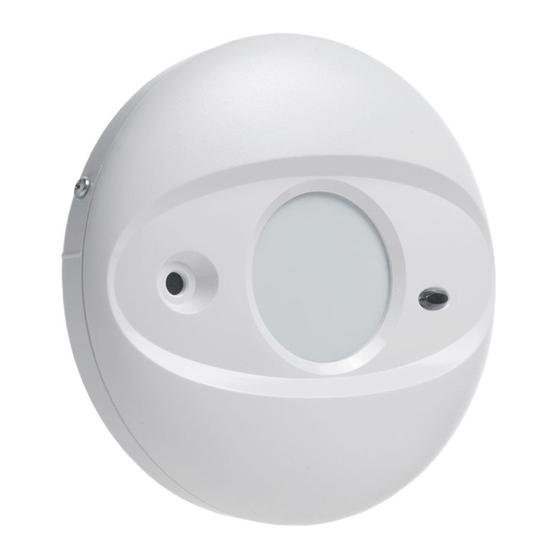
AC-500
Glassbreak Detector
Installation Instructions
The Acuity AC-500 is a glassbreak detector designed to
provide reliable protection for residential and commercial
applications.
The AC-500 is integrated with an advanced microprocessor
based glassbreak sensor, designed to detect the sounds
produced by the shattering of framed glass. The glassbreak
detection scheme used on the AC-500 is a result of an extensive
research program, which studies the properties of glass as well
as the properties of sounds produced by the shattering of
framed glass.
Features
• Omnidirectional microphone
• High level static and transient protection
• Excellent RF immunity
• Microcontroller-based digital signal processing
technology
• Dynamic Signal Processing* provides accurate detection of
plate, float, laminated, wired and tempered glass types,
while rejecting common "bell" or "ringing" type sounds
• White noise rejection mechanism
• Installer test mode for glassbreak sensor
• Alarm memory (latching LED) for glassbreak sensor
• 1 year warranty
Specifications
• Input Voltage .................................................. 9 - 14.5 V
• Current ...................... 24mA standby/32mA max.@12V
• Alarm Relay: Contact Rating ........................ 1.0A@24V
• Tamper Switch: Contact Rating ................... 0.1A@24V
• Microphone Type ....................... Omnidirectional Electret
• Size
(diameter x height) .......
4.6" x 1.4" / 117 mm x 36 mm
Glassbreak Detector Range
Glass
Sizes
Max. Range
Thickness
Type
L x W
Level 1 Detection
18"x18"/
1/8"/3.17mm
25ft./ 7.5m
Plate/Float/
0.45x0.45m and up
to
Tempered
12"x12"/ 0.3x0.3 m to
1/4"/6.35mm
15ft./ 4.6m
18"x18"/ 0.45x0.45m
18"x18"/
20ft./ 6m
Wired/
1/4"/
0.45x0.45m and up
Laminated
6.35mm
12"x12"/ 0.3x0.3 m to
10ft./3m
18"x18"/ 0.45x0.45m
Jumper Setting
• J1 Installer Test Mode
• J2 Alarm Memory
• J5 Glassbreak Detection Level*
Jumper
ON
J1
Glassbreak range test (AFT-100)
J2
LED latch for glassbreak
Level 2 detection with
J5 *
lower glassbreak sensitivity
* For UL Installations, only Level 1 detection must be used.
Environmental/Immunity
• RF Immunity (Not verified by UL/ULC) :
Radiated -10V/m +80% AM (@1KHz) from 80MHz to 1GHz
Conducted -10V +80% AM (@1KHz) from 150KHz to 80MHz
• Transients @ wiring terminal: 2.4KV @ 1.2joules
• Operating temperature: 32 -122°F / 0 - 50°C
• Humidity 5 - 95% RH non-condensing
Product Information
AC-500: Form 'A' alarm contact.
AC-501: Form 'A' alarm contact with tamper switch
AC-502: Form 'C' alarm contact with tamper switch
Locating the Detector
Acuity AC-500
NOTE: Maximum distance 'D' is limited by the range
(refer to the Glassbreak Detector Range chart)
* Patented
For optimum glassbreak protection, the detector should have a
clear view of the protected glass. Curtains, blinds, and other
window coverings will absorb sound energy from the shattering
DC
glass. In these cases, mount the detector as close as possible
DC
to the protected glass.
DC
OTE: : : : : Do not mount the detector on the same wall as the
N
DC
protected glass.
Avoid installation near noise sources, such as speakers or
other objects, which produce sounds continuously. Do not
install the detector beyond the maximum recommended range,
* Max. Range
even if the AFT-100 shows additional range - future changes
Level 2 Detection
in room acoustics could reduce that additional range.
15ft./ 4.6m
OTE: : : : : The AFT-100 Glassbreak Simulator will provide the
N
10ft./3m
most reliable and accurate indication of the correct mounting
location for the detector. Other simulators may trip the unit, but
Do not use
will not provide accurate indications.
Do not use
firealarmresources.com
Test for false alarm immunity by creating any sounds in the
room which will likely occur when the detector is armed.
Consider the following to reduce false alarms:
Noise Sources
Although the Acuity AC-500 is designed to be immune from
OFF
ringing, bell and white noise sounds, avoid mounting the
detector near such sources (e.g., telephones, doorbells,
Normal operation
Normal operation
alarm bells/sirens, air conditioner units, water pipes, etc.).
Level 1 detection with
NOTE: Application on 24 hr loops should be avoided unless
high glassbreak sensitivity
th premises are unoccupied.
Mounting
To open the case, gently twist the top cover counter-
clockwise and lift it up from the bottom cover. Use a small
screwdriver to remove the appropriate knockouts for wiring.
Mount the bottom cover using the screws supplied.
To close the case, use the locating line on the bottom cover
to align the tab on the top cover. Once the top cover is
engaged, twist the top cover clockwise to lock it in place.
Use the securing screw provided for Listed installations.
NOTE: Since no adjustment is necessary for the circuit
board, it is not recommended that the installer remove the
circuit board from the case. The microphone should NOT be
touched.
Wiring
Acuity AC-500
Refer to the following diagram for wiring instructions:
Minimum
6ft (1.8m)
Power
Contacts shown with power applied in the non-alarm state
NOTE: The unit must be connected to a Listed power supply
capable of providing 4 hours of standby power.
NOTE: After installation, the detector should be tested
annually by the installer.
Glassbreak
Tamper
Alarm
Contacts
Contacts
TAMP
Option
Option
Advertisement

Summary of Contents for DSC AC-500
- Page 1 Conducted -10V +80% AM (@1KHz) from 150KHz to 80MHz screwdriver to remove the appropriate knockouts for wiring. detection scheme used on the AC-500 is a result of an extensive Mount the bottom cover using the screws supplied. • Transients @ wiring terminal: 2.4KV @ 1.2joules...
- Page 2 FCC Compliance Statement CAUTION: Changes or modifications not expressly approved by Digital Security The Acuity AC-500 comes with a detection level jumper setting Controls Ltd. could void your authority to use this equipment. (Jumper J5), which allows the selection of one of 2 levels of...


Need help?
Do you have a question about the AC-500 and is the answer not in the manual?
Questions and answers