Table of Contents
Advertisement
Advertisement
Table of Contents
Troubleshooting

Related Manuals for Alpha ESS SMILE-G3-S5


Summary of Contents for Alpha ESS SMILE-G3-S5
- Page 1 SMILE-G3-S5 /SMILE-G3-S3.6/SMILE-G3-B5 INSTAL LE-G3-S5-INV...
- Page 2 Copyright Statement This manual is under the copyright of Alpha ESS Co., Ltd. with all rights reserved. Please keep the manual properly and operate in strict accordance with all safety and operating instructions in this manual. Please do not operate the product before reading through the...
-
Page 3: Table Of Contents
CONTENT INFORMATION ON THIS DOCUMENT 1.1 Information on this Document 1.2 Target Group 1.3 Levels of Warning Messages 1.4 Nomenclature SAFETY 2.1 Intended Use of the Inverter 2.2 Safety Precaution for Battery Pack 2.2.1 General safety precautions 2.2.2 Response to emergency situations Important Safety Instructions Symbols on the label PRODUCT INTRODUCTION AND APPLICATION SCENARIOS... - Page 4 7.2 Preparing Cables 7.3 Connecting Additional Grounding 7.4 AC Connection 7.5 Communication Connection 7.6 PV Connection 7.7 Battery Power Connection 7.8 Battery Pack Expansion Connection WIFI SETTING 8.1 Download and Install APP 8.2 Overview of Functions for Installer Account 8.3 WiFi Module Setting COMMISSIONING 9.1 Checking Before Power-On 9.2 Check the Running State...
-
Page 5: Information On This Document
Information on this Document 1.1 Content and Structure of this Document This document is valid for product of SMILE-G3 series which include inverter SMILE-G3-S5-INV, SMILE-G3-S3.6-INV, SMILE-G3-B5-INV, battery pack SMILE-G3-BAT- 10.1P. This document describes the mounting, installation, commissioning, configuration, operation, troubleshooting and decommissioning of the product as well as the operation of the product user interface. -
Page 6: Nomenclature
INFORMATION provides tips which are valuable for the optimal installation and operation of the product. 1.4 Nomenclature Complete designation Designation in this document SMILE-G3-S5-INV 5kW DC coupled hybrid inverter (Outdoor) SMILE-G3-S3.6-INV 3.6kW DC coupled hybrid inverter (Outdoor) SMILE-G3-B5-INV 5kW AC coupled hybrid inverter (Outdoor) SMILE-G3-BAT-10.1P... -
Page 7: Safety
SAFETY Safety 2.1 Intended Use of the Inverter The inverter, the battery pack, the energy meters make up a system for optimization of self-consumption in a household. The inverter is equipped with two MPP trackers (only for S5&S3.6, SMILE-G3-B5 does not have MPPT) and converts the direct current from the PV array into grid-compliant single-phase current and feeds it into the utility grid. -
Page 8: Response To Emergency Situations
SAFETY 2.2.2 Response to emergency situations The battery pack comprises multiple batteries that are designed to prevent hazards resulting from failures. However, AlphaESS cannot guarantee their absolute safety. • If a user happens to be exposed to internal materials of the battery cell due to damage on the outer casing, the following actions are recommended. -
Page 9: Important Safety Instructions
SAFETY 2.3 Important Safety Instructions This section contains safety precautions that must be observed at all times when working on or with the product. To prevent personal injury and property damage and to ensure long-term operation of the product, read this section carefully and follow all safety precautions at all times. DANGER Danger to life due to electric shock when live components or cables are touched. - Page 10 SAFETY DANGER Danger to life due to electric shock when touching live system components in case of a ground fault. If a ground fault occurs, parts of the system may still be live. Touching live parts and cables results in death or lethal injuries due to electric shock. Disconnect the product from voltage sources and make sure it cannot be reconnected before working on the device.
- Page 11 SAFETY CAUTION The heatsink and housing can get hot during operation. NOTICE Damage to the inverter due to electrostatic discharge Touching electronic components can cause damage to or destroy the inverter through electrostatic discharge. Ground yourself before touching any component. NOTICE Damage due to cleaning agents The use of cleaning agents may cause damage to the product and its components.
-
Page 12: Symbols On The Label
SAFETY 2.4 Symbols on the label Symbols on the type label of the inverter Symbol Explanation Beware of a danger zone This symbol indicates that the product must be additionally grounded if additional grounding or equipotential bonding is required at the installation site. - Page 13 SAFETY Symbols on the type label and warning label of the battery pack Symbol Explanation Beware of a danger zone This symbol indicates that the product must be additionally grounded if additional grounding or equipotential bonding is required at the installation site. Beware of electrical voltage The product operates at high voltages.
-
Page 14: Product Introduction And Application Scenarios
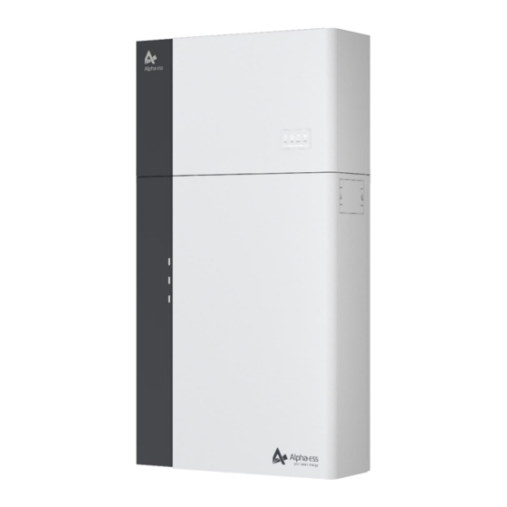
PRODUCT INTRODUCTION AND APPLICATION SCENARIOS Product Introduction and Application Scenarios 3.1 Inverter Description Inverter appearance and dimensions Inverter LED Signals Five LED indicators and one reset button are provided on the display panel. These LED indicators provide information about the operational status of the system. Status Explanation Status... - Page 15 PRODUCT INTRODUCTION AND APPLICATION SCENARIOS Status Explanation Status Explanation When White light When White light Meter communication works Disconnect to the server normally When no light When no light Meter lost Disconnect to the server...
-
Page 16: Battery Pack Description
3.2 Battery Pack Description Battery pack appearance and dimensions SMILE-G3-BAT-10.1P Battery pack appearance and dimensions Battery Pack Dimension (W*H*D) SMILE-G3-S5-INV (OUTDOOR) 610*780*212 mm SMILE-G3-S3.6-INV (OUTDOOR) 610*780*212 mm SMILE-G3-B5-INV (OUTDOOR) 610*780*212 mm Four LED indicators are provided on the display panel. -
Page 17: Application Scenarios
SOC is between 80% and 100%, the fourth line of the LED indicator will flash every 3s. 3.3 Application Scenarios AlphaESS SMILE-G3-S5 system (include SMILE-G3-S5-INV and SMILE-G3-BAT- 10.1P) can be applied in DC-coupled systems with PV strings, AC-coupled systems, hybrid-coupled systems, and Off-grid (with Generator) systems as... - Page 18 PRODUCT INTRODUCTION AND APPLICATION SCENARIOS Indicates a power cable Indicates a signal cable DC-coupled Storage System–Scheme Indicates a power cable Indicates a signal cable AC-coupled Storage System–Scheme Indicates a power cable Indicates a signal cable Hybrid-coupled Storage System–Scheme...
-
Page 19: Storage
STORAGE Storage 4.1 Inverter Storage The following requirements should be met if the inverter is not put into use directly: 1. Do not unpack the inverter. 2. Keep the storage temperature at -40~70° C and the humidity at 5%~95% RH. 3. -
Page 20: Unpacking
5.2 Scope of Delivery Check the scope of delivery for completeness and any externally visible damage. Contact your distributor if the scope of delivery is incomplete or damaged. * Items only for SMILE-G5-S5/S3.6-INV SMILE-G3-S5/S3.6/B5-INV Hybrid Inverter Left decorate Inverter TOP decorate plate... - Page 21 UNPACKING SMILE-G3-BAT-10.1P Battery Pack Floor Gasket Battery Positioning Battery Wall (X1) (X3) Paper Plate (X1) Bracket (X1) Wall Anchor Cardboard limit board Battery COM Cable Power Cable + (X 1) ST6*55 (X4) (X1) (X1) Power Cable - (X 1) Guide Foot Pad(X2) Screw M5*10(X8) Quick Installation...
- Page 22 Screw M5*12 (X3) Side Gasket (X1)
-
Page 23: Mounting
Do not mount the product in areas containing highly flammable materials or gases. Do not mount the product in potentially explosive atmospheres. Basic Requirements SMILE-G3-S5-INV, SMILE-G3-S3.6-INV, SMILE-G3-B5-INV, SMILE-G3-BAT-10.1P suitable for indoor and outdoor use. SMILE-G3 cannot use for multiple phase combinations Do not install the inverter in a place where a person can easily touch because its housing and heatsink are hot during operation. - Page 24 MOUNTING Mounting Angle and Stack Requirement SMILE-G3-BAT-10.1P should be floor-mounted. SMILE-G3-S5-INV should be wall-mounted. The installation angle requirement is as follow: • Do not mount the battery pack and inverter at forward tilted, back tilted, side tilted, horizontal, or upside down positions.
-
Page 25: Preparing Tools And Instruments
MOUNTING 6.2 Preparing Tools and Instruments Category Tools and Instruments Multimeter (DC voltage Hammer drill (with a Torque socket measurement range ≥ Ф10 mm drill bit) wrench SW10 1000 V DC) Phillips screwdriver, torque range: 0-2 N m) Diagonal pliers Wire stripper L≥140mm Rubber mallet... -
Page 26: Mounting The Smile-G3-Bat-10.1P And Inverter
MOUNTING 6.3 Mounting the SMILE-G3-BAT-10.1P and Inverter 6.3.1 Mounting the battery pack 1. Lift the battery pack by using the handles at the two sides, take it out from the package carton. Do not put the battery pack upside down on the ground. 2. - Page 27 MOUNTING 4. After cleaning the dust and other objects from the two holes, place 2 wall anchors into the holes, then attach the battery wall bracket to the wall by using the SW10 hexagon sleeve. Please use a level to ensure that the wall bracket is horizontal. 5.
- Page 28 MOUNTING 7. Tighten the wall bracket and the battery pack with screw M5*12 (X 2) (tool: T20 screwdriver, torque: 2.5Nm). If the floor of installation site is uneven, please use floor gaskets to level at the bottom of the battery pack gasket WARNING Risk of injury when lifting the battery pack, or if it is dropped...
- Page 29 MOUNTING 2) For battery stack, lock the screw M6*6 on top of the first battery pack. 3) Place the battery positioning paper plate against the wall and the bottom with notch against the first battery pack. Repeat steps 1-7. 4) The bottom limit holes of the second battery will match the top screws of the first battery.
- Page 30 MOUNTING 6.3.2 Mounting the inverter The steps to mount the inverter are listed below: 1. Fit the left and right side brackets onto the top of the battery. 2. Attach the inverter to the mounting bracket. Mount the supporting bracket at the bottom of the inverter.
- Page 31 1. Mounting more batteries You can install extra batteries up to 6 batteries in a system. 1) If the expansion batteries are installed downwards: Attach the positioning paper plate to the first wall bracket, and mark the wall through holes (A2 and A1) on the paper plate. Use a hammer drill (Φ10.0mm; length 20cm) to drill holes in A1 and A2 with a depth of about 7cm and fix the wall bracket tightly to the wall with expansion screws.
-
Page 32: Mounting The Wifi Module
MOUNTING 4) If the expansion batteries are installed by side: Position the positioning paper plate according to the installed batteries, and then repeat steps 3-9 to install the expansion batteries. 6.4 Mounting the Wi-Fi Module 1. Remove the Wi-Fi Silicone dust cover from the left of the inverter. 2. -
Page 33: Electrical Connection
ELECTRICAL CONNECTION Electrical Connection Precautions DANGER Before connecting cables, ensure that all switches and breakers of the inverter and the battery pack and all the switches connected to inverter and the battery pack are set to OFF. Otherwise, the high voltage of the product may result in electric shocks. - Page 34 ELECTRICAL CONNECTION Position Designation Grid connection port Backup connection port Positive BAT power connector Negative BAT power connector Battery breaker** Positive and Negative PV connectors, PV 1/ PV2 PV switch Connection port for the WiFi module Communication port(BMS, CAN/RS485, Meter/Grid-CT, DRM*, LAN, AUX )...
- Page 35 ELECTRICAL CONNECTION 7.1.2 Overview of the Battery Pack Connection Area The battery breaker is switched off before delivery a) SMILE-G3-BAT-10.1P (OUTDOOR) Battery Breaker BAT+ Connectors Communication Connectors BAT+ Connectors Battery Power Button BAT- Connectors...
-
Page 36: Preparing Cables
ELECTRICAL CONNECTION 7.2 Preparing Cables Outer Conductor Cross Cable Type Source Diameter Section Area Range Standard PV cable in the Delivered Battery 16 mm industry (recommended with the power cable type: PV1-F) battery pack Standard network cable in the Battery Delivered 0.12 ~... -
Page 37: Connecting Additional Grounding
ELECTRICAL CONNECTION 7.3 Connecting Additional Grounding An external grounding connection is provided at the left side of the inverter. Prepare M5 OT terminals, strip the grounding cable insulation, insert the stripped part of the grounding cable into the ring terminal lug and crimp using a crimping tool. Connect the OT terminal with ground point using the torque is 2.5 Nm with T20 screwdriver. -
Page 38: Ac Connection
ELECTRICAL CONNECTION 7.4 AC Connection 7.4.1 Conditions for the AC Connection AC breakers must be installed on the AC side of the inverter to ensure that the inverters can be safely disconnected from the power grid and the load. DANGER Danger to life due to fire! You must protect each inverter with an individual AC circuit breaker in order to ensure that the inverter can be disconnected safely. - Page 39 ELECTRICAL CONNECTION 7.4.2 Grid and Backup Connection Grid Connection Unscrew the swivel nut and take out the Seal ring from the threaded sleeve, Insert the crimped conductors L, N and PE into the corresponding terminals and tighten the screw with torque 2.0Nm Assemble the socket element, adapter and swivel nut together.
- Page 40 NOTICE For Australia and New Zealand installation site, the neutral cable of the grid side and backup side must be connected together at the neutral bar, otherwise the backup output function will not work. Please refer to Appendix 3 for more details. 2.
- Page 41 For AC-coupled systems and Hybrid-coupled systems, another PV-CT is required . Buckle the PV-CT on the live wire of the PV inverter connecting point and insert the registered jack of the PV-CT cable into the PV-CT port on the SMILE-G3-S5-INV. NOTE: The arrow of the CT should point to the grid port of the inverter from the grid or the PV inverter.
- Page 42 ELECTRICAL CONNECTION PV Inverter LOAD 7.4.5 Meter Connection The system supports the following two different metering schemes in order to record the feed-in power and consumption from grid: DTSU666-3*230V 5A: Three/single-phase meter (without CT) DTSU666-100/40mA: Three/single-phase meter (with 3 or 6 CT) Meter wiring introduction NOTICE If the extra PV inverter are not used, the system is suitable for DC mode.
- Page 43 ELECTRICAL CONNECTION Wiring at three-phase home 2. DTSU666-100/40mA: Three-phase meter (with 3 or 6 CTs) connection PV CT Optional SMILE-S6-HV-INV PV Inverter LOAD Wiring at single-phase home 39 36 33 37 34 31 SMILE-S6-HV PV Inverter LOAD Wiring at three-phase home...
- Page 44 ELECTRICAL CONNECTION Grid CT PV CT 1 ---------IC (White) 31 -------- IC (White) 3 -------- IC (Blue) 33 -------- IC (Blue) 4 ---------IB (White) 34 -------- IB (White) 6 -------- IB (Blue) 36 -------- IB (Blue) 7 --------- IA (White) 37 -------- IA (White) 9 -------- IA (Blue) 39 -------- IA (Blue)
- Page 45 ELECTRICAL CONNECTION *1 ( Step1) *2 ( Step2) 2. DTSU666-100/40mA: Three-phase meter (with CT) When the meter is used as Grid meter, please follow the steps below to complete the address setting by pressing the corresponding button and the number of times. →...
-
Page 46: Communication Connection
ELECTRICAL CONNECTION Meter Setting on AlphaAPP When the system work mode is selected as DC, only tick the “Meter” on the right of the “Grid Meter”. When the system work mode is selected as AC or Hybrid, both tick the “Meter” on the right of the “Grid Meter”... - Page 47 Response Enabling Device (DRED). This ensures that the system implements the commands from the grid operator for active power limitation at all times. The system and the Demand Response Enabling Device (DRED) must be connected in the same network. Only DRM0 is available for SMILE-G3-S5-INV/ SMILE-G3-S3.6-INV/ SMILE-G3-B5-INV.
- Page 48 ELECTRICAL CONNECTION 3) Take out 10 pin terminal block for AUX connection. AUX contains Channel1 and Channel2.Channel1 contains Do1_NO (normally open), Do1_COM and Do1_NC (normally closed), corresponding to 1, 2 and 3 respectively. Channel2 contains Do2_NO, Do2_COM and Do2_NC, corresponding to 4, 5 and 6 respectively. Channel 1 Do1_NO Do1_COM...
-
Page 49: Pv Connection
ELECTRICAL CONNECTION 7.6 PV Connection Please ensure the follows before connecting PV strings to the inverter: Make sure the voltage of the PV string will not exceed the max. DC input voltage (600Vdc). Violating this condition will void the warranty. Make sure the polarity of the PV connectors is correct. -
Page 50: Battery Pack Expansion Connection
ELECTRICAL CONNECTION 7.8 Battery Pack Expansion Connection You can install extra batteries up to 6 batteries in a system. Please install extra SMILE-G3-BAT-10.1P batteries by side, also batteries can be stacked up to two batteries per column. Connect the power cables from battery 2 to battery 1. Connect the BMS communication cables from battery 2 to battery 1. - Page 51 ELECTRICAL CONNECTION Install extra SMILE-BAT-5PH batteries Take out the terminal resistor provided by the inverter, insert it to the unused communication port of the last battery. SMILE-G3-BAT-10.1P (OUTDOOR)
- Page 52 WIFI SETTING 7.9 Install decorative cover Install the top decorative cover Install the Right decorative cover...
- Page 53 Install the Left plastic decorative cover...
- Page 54 WiFi Setting 8.1 Download and Install APP Android device users can download the APP through major Android application markets such as Google Play. IOS device users can search for “AlphaESS” in App Store and download the APP. AlphaESS-APP...
-
Page 55: Wifi Setting
WIFI SETTING 8.2 Overview of Functions for Installer Account... -
Page 56: Wifi Module Setting
WIFI SETTING 8.3 Wi-Fi Module Setting This section is for users who have a system with a Wi-Fi module. AlphaESS App supports network configuration, setting of the system basic parameter, and the viewing of system operation and configuration information. After that please check Open AlphaESS APP, click whether your mobile phone has the “Wi-Fi Configuration”... - Page 57 WIFI SETTING Select the Wi-Fi of your home you are using, enter the password, complete the Wi-Fi configuration and submit. If there is no network currently, you can click Jump over to skip the Wi-Fi configuration step and directly set the system parameters. NOTE: The system will not be able to connect to the Internet without Wi-Fi configur...
- Page 58 COMMISSIONING The max feed-in can be set after chosen the safety regulation in the same page. After finishing the WIFI setting, all the status can be found on the main page. The firmware version also can be checked in the ‘Firmware information’. * The end user can contact the installer or service center for updating service...
-
Page 59: Commissioning
Commissioning 9.1 Checking Before Power-On Check Item Acceptance Criteria The mounting space is proper, and the mounting Mounting environment environment is clean and tidy, without foreign object. The battery pack and inverter are mounted Battery pack and correctly, securely, and reliably. inverter mounting The Wi-Fi module is mounted correctly, Wi-Fi mounting... -
Page 60: Check The Running State
COMMISSIONING 9.3 Check the Running State Prerequisites Before switching on the AC breaker between the inverter and the grid, check that the AC voltage on the power grid side of the AC breaker is within the specified range. Please select the acceptance of installation on site when the light intensity is strong. Procedure 1. -
Page 61: Powering Off The Product
9.4 Powering Off the Product WARNING After the inverter and battery pack is powered off, the remaining electricity and heat may still cause electric shocks and body burns. Therefore, put on protective gloves and operate the product 5 minutes after the power-off. Procedure 1. -
Page 62: Maintenance And Troubleshooting
MAINTENANCE AND TROUBLESHOOTING Maintenance and Troubleshooting 10.1 Routine Maintenance Normally, the inverter and battery pack need no maintenance or calibration. However, in order to maintain the accuracy of the SOC, it is recommended to perform a full charge calibration for SOC (charging battery until the charging power is 0) on the battery at regular intervals (such as two weeks). -
Page 63: Troubleshooting
MAINTENANCE AND TROUBLESHOOTING 10.2 Troubleshooting 10.2.1 Inverter Error Troubleshooting Error No. Error description Solution Grid_OVP 100000 1. Check whether Grid is abnormal. Grid_UVP 100001 2. Confirm whether the grid cable connection is Grid_OFP 100002 normal. 3. Restart inverter and ensure whether the fault Grid_UFP 100003 is existing. - Page 64 MAINTENANCE AND TROUBLESHOOTING Error No. Error description Solution Check the PV1 voltage. If it exceeds 585VDC, MPPT1_OVP 100017 reduce the number of PV modules. 1. Try to reduce the PV power. MPPT1_SW_OCP 100018 2. Restart the inverter to see if the fault still exists. MPPT1_HW_OCP 100019 If it still exists, please call the service center.
- Page 65 MAINTENANCE AND TROUBLESHOOTING Error No. Error description Solution 1. Try to lower the ambient temperature. 2. Make sure that the inverter is installed according to the manual and there is no shelter around the INV_OTP inverter. 100035 3. After the inverter is powered off and waiting for 30 minutes, then restart it.
- Page 66 MAINTENANCE AND TROUBLESHOOTING Error No. Error description Solution 1. If the battery is not connected, use a multimeter to measure whether there is voltage at the battery battery_stops_ terminal. 110005 running_alarm 2. Restart the inverter to see if the fault still exists. If it still exists, please call the service center.
- Page 67 MAINTENANCE AND TROUBLESHOOTING 10.2.3 Battery Error Description LED Indictor Description Troubleshooting Error Code Display Hardware error Error 01 Hardware error Error 02 Wait for automatical recovery. If the problem is not be solved yet, please call the service Hardware error Error 03 center.
-
Page 68: Uninstallation & Return
UNINSTALLATION & RETURN Uninstallation & Return 11.1 Removing the Product Procedure Step 1 Power off the product by following instructions in chapter 9.3 Powering Off the Product. Step 2 Disconnect all cables from the product, including communication cables, PV power cables, battery power cables, AC cables, and PE cables. Step 3 Remove the WiFi module from the inverter. -
Page 69: Specification
SPECIFICATION Specification 12.1 Datasheet of SMILE-G3 Item SMILE-G3-S5-INV SMILE-G3-S3.6-INV SMILE-G3-B5-INV Input DC (PV side) Recommended max. 7500 5400 PV power Max. PV input voltage 580 V Rated voltage 360 V Start-up voltage 100 V MPPT voltage range 90 ~ 550 V Max. - Page 70 SPECIFICATION L/N/PE, 230 V Rated Output Current 50/60 Hz Rated Frequency 10 kW Rated Input Power 43.5 A Max. input current Output AC(Grid side) 5 kW 3.6 kW 5 kW Rated output power 5 kVA 3.6 kVA 5 kVA Max. Apparent Output Power Operation Phase Single phase...
-
Page 71: Datasheet Of Battery Pack Smile-G3-Bat-10.1P
General data 580*440*230 mm Dimensions(W*H*D) Weight 25 kg Topology Transformerless Operation Temperature -25 ~ +60 ° C Range Ingress Protection IP65 Noise Emission <30 dB(A) @1m Cooling Concept Natural convection Max. Operation Altitude 3000 m G98/G99, VDE-AR-N 4105, EN 50549-1, VDE 0126, RD 1699, Grid Connection Standard CEI 0-21, C10/11, NRS 097-2-1, Tor Erzeuger, MEA, PEA, AS/NZW 4777.2, IEEE1547... - Page 72 SPECIFICATION Internal Resistance ≤90 mΩ Max. Charging/ 0.5C (52.2 A) Discharging Current** Operating Temperature Charge:0<T<50° C / Discharge:-10<T<50° C Range Relative Humidity 0% ~ 95% System voltage, current, cell voltage, Monitoring Parameters cell temperature, PCBA temperature Communication CAN and RS485 compatible Safety IEC62619(Cell), IEC 62619(Pack) Transportation...
-
Page 73: Appendix 1:Communication Connection Figure
COMMUNICATION CONNECTION FIGURE Appendix 1:Communication Connection Figure SMILE-G3-S5-INV for example SMILE-G3-S5-INV Other SMILE SMILE Indicates a signal cable Optional Connect the CT SMILE-G3-S5-INV Other SMILE PV Meter Grid Meter SMILE Connect the meter NOTICE If the extra PV inverter is not used, the system is suitable for DC mode. -
Page 74: Appendix 2: Regional Application Standard
Volt-Watt will run automatically. (Only for Australia) For compliance with AS/NZS 4777.2:2020 please select from Australia A/B/C. Please contact your local electricity grid operator for which region to select. For changes to default settings please contact the installer or Alpha ESS ... - Page 75 Appendix 3: System Connection Diagrams Example for application that Neutral connects together with PE in distribution box, such as Australia, New Zealand, South Africa, etc. (Please follow local wiring regulations!) Example for grid systems without special requirements on electrical wiring connection.
- Page 76 @AlphaEnergyStorageSystem @AlphaESS @alpha_ess @AlphaESS www.alpha-ess.com Alpha ESS Co., Ltd. Alpha ESS Suzhou Co., Ltd. +86 513 8060 6891 +86 512 6828 7609 info@alpha-ess.com info@alpha-ess.com www.alpha-ess.com www.alpha-ess.com Building 10-A, Canal Town Industrial Park, JiuHua Road 888, High-Tech Industrial Development 99 Taihu E Rd, Wuzhong District, Suzhou 215000...
Need help?
Do you have a question about the SMILE-G3-S5 and is the answer not in the manual?
Questions and answers