Table of Contents
Advertisement
Quick Links
Advertisement
Table of Contents

Related Manuals for Miele CS 1011


Summary of Contents for Miele CS 1011
- Page 1 Operating and installation instructions Gas cooktops CS 1011 en - AU, NZ To avoid the risk of accidents or damage to the appliance it is essential to read these instructions before it is installed and used for the first time.
- Page 2 WO This appliance can be used in countries other than those specified on the appliance. It is, however, set up for connection to the gas and electricity supplies in the countries specified. For use in other countries please contact the Miele Spare Parts Department or Miele Customer Contact Centre in your country.
-
Page 3: Table Of Contents
Contents Guide to the appliance ..........5 Cooktop . - Page 4 Contents Installation of several appliances........32 Fixing the spring clamps and spacer bars .
-
Page 5: Guide To The Appliance
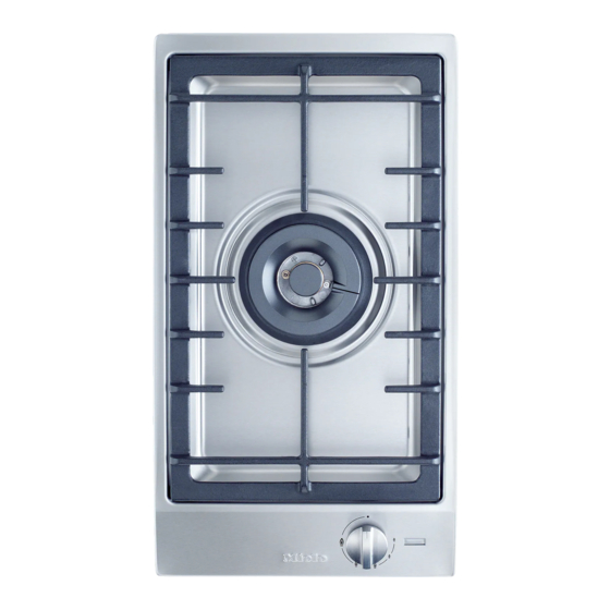
Guide to the appliance Cooktop a Wok burner b Pan support c Control knob d Display Display e In-operation indicator f Residual heat indicator... - Page 6 Guide to the appliance Burner g Inner burner cap h Outer burner cap i Burner ring j Burner head k Ignition safety device l Ignitor m Burner base...
-
Page 7: Accessories Supplied
Guide to the appliance Accessories supplied The accessories supplied with your CombiSet appliance as well as a range of optional ones are available to order (see "Optional accessories"). Wok ring The Wok ring supplied with your appliance can be used in instances where extra stability is required. -
Page 8: Warning And Safety Instructions
Warning and safety instructions Correct use This appliance complies with all This appliance is intended for relevant local and national safety domestic use only and must be used as requirements. Improper use of the described in these instructions. appliance can, however, present a Any other usage is not permitted and risk of both personal injury and could be dangerous. - Page 9 Warning and safety instructions Safety with children Packaging, e.g. cling film, polystyrene and plastic wrappings, Children should be supervised to must be kept out of the reach of babies ensure that they do not play with the and young children. Danger of appliance.
- Page 10 H 05 V V-F earthing system (e.g. electric shock). (pvc insulated), available from Miele. Before connecting the appliance to Never open the outer casing of the the mains supply, make sure that the appliance.
- Page 11 This could result in injury and scalding or damage. Faulty components must only be replaced by genuine Miele original Do not use the appliance to heat up spare parts. The manufacturer can only the room. Due to the high temperatures...
- Page 12 Warning and safety instructions Pans must be the correct size for the Do not cover the appliance, e.g. burner they are used on (see "Pans"). A with a cloth, kitchen foil, etc. This could pan which is too small will be unstable be a fire hazard if the appliance is on the pan support.
- Page 13 Warning and safety instructions Replace the pan supports carefully Spray canisters, aerosols and other to avoid scratching the surface of the inflammable substances must not be cooktop. stored in a drawer under the cooktop. Cutlery inserts must be heat-resistant. Using the gas cooktop will cause a build-up of heat and moisture in the Do not spray aerosols in the vicinity room in which it is installed.
-
Page 14: Caring For The Environment
Caring for the environment Disposal of the packing Disposal of your old appliance material or machine The transport and protective packing Electrical and electronic appliances / has been selected from materials which machines often contain materials are environmentally friendly for disposal which, if handled or disposed of and can normally be recycled. -
Page 15: Before Using For The First Time
Before using for the first time Please adhere the extra data plate for the appliance supplied with this documentation in the space provided in the "After sales service" section of this booklet. Cleaning for the first time ^ Remove any protective foil and adhesive labels. -
Page 16: Operation
Operation Rapid ignition system The burner can only be switched on The appliance is supplied with a rapid by pushing in the control and turning ignition system with the following it anti-clockwise,. It is switched off features: by turning the control clockwise. The –... - Page 17 Operation Switching on Regulating the flame Control the flame so that it does not Do not leave the appliance spread out beyond the sides of the unattended whilst it is being used. pan. As the outer part of the flame is much hotter than the centre, the tips of the flames should stay beneath the pan base.
-
Page 18: In-Operation Indicator And Residual Heat Indicator
Operation In-operation indicator and Residual heat indicator When the gas cooktop is switched on, the in-operation indicator lights up. Once it has reached a certain temperature, the residual heat indicator also lights up. The in-operation indicator goes out when the gas cooktop is switched off. -
Page 19: Pans
Pans – Use the correct sized pans for your Min. base diameter appliance. A pan which is too small Pots / pans = 15 cm will be unstable on the pan support. If the pan diameter is too large, Max. rim diameter flames can spread out to the sides Pots / pans = 24 cm and damage or burn the worktop,... -
Page 20: Safety Features
Safety features Thermo-electric ignition Safety cut-out This appliance has a thermo-electric If a burner has been used for an ignition safety device. If the flame goes unusually long period (approx. 4 out, for example if food has boiled over hours), it will switch off automatically. or if there is a sudden draught, and To use the burner again, turn the automatic re-ignition has been... -
Page 21: Cleaning And Care
Cleaning and care General notes To avoid damaging the surface or your cooktop, do not use: Under no circumstances use a – cleaning agents containing soda, steam cleaning appliance to clean alkaline, ammonia, acids or this appliance. The steam could chlorides, attack the electrical components and cause a short circuit. -
Page 22: Stainless Steel Surfaces
Cleaning and care Stainless steel surfaces Pan support, control knob Clean stainless steel surfaces using a Remove the pan support. Clean the solution of warm water and a small pan support and the control knob with a amount of washing-up liquid applied solution of warm water and a small with a soft sponge. -
Page 23: Burner
Cleaning and care Burner Reassemble the burner Do not clean any parts of the burner in a dishwasher. The burner should be dismantled and then cleaned by hand using a solution of warm water and a small amount of washing-up liquid applied with a soft sponge. -
Page 24: Problem Solving Guide
Problem solving guide ... the in-operation indicator is Repairs to the gas and electrical flashing. components of this appliance must There is no supply of gas. only be carried out by a suitably qualified and competent person to Turn all the controls clockwise to ensure safety. - Page 25 Check whether – the mains fuse has tripped. If it has, contact a qualified electrician or the Miele Customer Contact Centre. – food deposits have lodged themselves between the ignitor and the burner cap. Remove any food deposits carefully (see "Cleaning and care").
-
Page 26: Optional Accessories
Optional accessories Miele branded cleaning and conditioning products are available for your appliance. These can be ordered via the internet at www.miele-shop.com (depending on country) or from the Miele Spare Parts Department (see back cover). Ceramic and stainless steel cooktop cleaner 250 ml... -
Page 27: Safety Instructions For Installation
Safety instructions for installation It can be installed above an oven. Fit wall units and rangehood before The worktop must be at least 40 mm fitting the cooktop to avoid thick. damaging the surface. Ensure that the gas pipe and electrical cable are installed in such a This appliance must not be way that they do not touch any parts of... -
Page 28: Safety Clearances
Safety clearances Safety clearance above the cooktop Side / rear clearances to the cooktop Ideally the cooktop should be installed with plenty of space on either side. There may be a wall at the rear and a tall unit or wall at one side. On the other side, however, no unit or divider should stand higher than the cooktop (see illustrations). - Page 29 Safety clearances Before installing the appliance check If the clearance between the periphery that the location provides the required of any gas burner and clearances from combustible material - the side wall is less than 300 mm and if necessary provide protection to - the rear wall is less than 200 mm, adjacent surfaces as required by the walls must be protected with a non...
-
Page 30: Appliance And Building-In Dimensions
Appliance and building-in dimensions a Spring clamps b Front c Building-in depth d Mains connection box with mains connection cable, L = 2,000 mm e Gas connection R 1/2 - ISO 7-1... -
Page 31: Preparing The Worktop
Preparing the worktop ^ Make the worktop cut-out following the dimensions applicable. Remember to maintain a minimum safety clearance from the back wall, as well as from any tall unit or side wall to the right or left of the appliance. -
Page 32: Installation Of Several Appliances
Installation of several appliances When installing two or more appliances next to each other a spacer bar b must be used between each one. See "Fitting the spacer bars and support brackets". Worktop cut-out Worktop cut-out - two appliances - three appliances When installing three appliances the When installing two appliances, the width of the cut-out required (D) is... - Page 33 Installation of several appliances Worktop cut-out calculation example for three appliances Appliance width Appliance Appliance width Worktop less 8 width less 8 cut-out 1032 1424 1124 1516 1136 1320 1136 All dimensions are given in mm...
- Page 34 Installation of several appliances 2 5 - 3 0 5 0 5 0 2 5 - 3 0 5 6 8 3 7 2 / 2 8 0 / 5 7 6 3 8 0 / 2 8 8 / 5 6 8 3 7 2 / 2 8 0 /...
-
Page 35: Fixing The Spring Clamps And Spacer Bars
Fixing the spring clamps and spacer bars Wooden worktops Granite and marble worktops The screws are not required for 2 5 - 3 0 granite or marble worktops. 2 5 - 3 0 ^ Position the spring clamps supplied a and spacer bars b on the top edge of the cut-out in the positions ^ Position and secure the spring marked. - Page 36 Fixing the spring clamps and spacer bars ^ Coat the side edges and the lower edges of the spring clamps with silicone. ^ Then fill gap d between the spacer bars and the worktop with silicone from the tube supplied.
-
Page 37: Installing / Removing The Appliance
Installing / removing the appliance Installing the appliance Removing the appliance ^ Feed the connection cable down If the appliance is accessible from through the cut-out. below, it can be pushed up and out of the cut-out. It must be pushed up from ^ Then drop the front edge of the the back first. -
Page 38: General Installation Tips
General installation tips Tiled worktop The grouting a and the shaded area underneath the appliance frame must Do not use sealant between the be smooth and even so that the frame frame of the top part of the sits evenly and the sealing strip appliance and the worktop. -
Page 39: Electrical Connection
As the colours of the wires in the mains connection cable of type H 05 V V-F lead of this appliance may not (pvc insulated), available from the Miele correspond with the coloured markings Spare Parts Department. identifying the terminals in your plug... -
Page 40: Gas Connection
Gas connection This appliance is set up for connection Connection to the gas supply, or to natural gas. conversion from one type of gas to See adhesive label on the appliance: another should only be undertaken G = NG (natural gas) by an approved gas fitter, who is LP = ULPG (Propane/Butane) responsible for correct functioning of... - Page 41 Gas connection Gas pressure must be set by the The gas connection must be in approved gas fitter as shown on the accordance with national and local data plate: regulations. Natural gas 1.0 kPa The relevant building regulations must also be observed. ULPG (Propane/Butane) 2.75 kPa ^ Disconnect gauge and screw in the...
-
Page 42: Conversion To Another Type Of Gas
Conversion to another type of gas Screw in the new jets according to the Connection to the gas supply, or following table. conversion from one type of gas to another, should only be undertaken Jet table by an approved and registered gas Main jet Small jet installer in strict accordance with... -
Page 43: Changing The Jets
Conversion to another type of gas Changing the jets Disconnect the gas cooktop from the electricity supply by switching off at the socket and withdrawing the plug or by disconnecting the mains fuse. Turn off the gas supply. To change the jets, the burner securing screws must first be loosened and the upper section of the appliance removed. - Page 44 Conversion to another type of gas ^ Whilst counterholding it in place with To change the jet for the inner burner an SW 12 spanner, remove screw c from fitting b using an SW 8 spanner. ^ Whilst counterholding it in place with an SW 12 spanner, remove screw fitting b from fitting a with another SW 12 spanner.
-
Page 45: To Check The First Intake Of Air
Conversion to another type of gas To check the first intake of air If it doesn't: ^ Loosen the retaining screw, adjust the air intake sleeve, and tighten the retaining screw again. ^ Finally secure the jets against inadvertent loosening with sealing wax. -
Page 46: To Change The Small Jets
Conversion to another type of gas ^ Using a small screwdriver, unscrew To change the small jets the two small jets a and b in the gas fitting. ^ Pull out the jets with a pair of pliers. ^ Fit the correct jets securely (see jet table). -
Page 47: After Changing The Jets
Conversion to another type of gas After changing the jets The flame must not go out on the lowest setting, or when the control is turned ^ Reassemble the burner parts in the quickly from a high to a low setting. reverse order. -
Page 48: After Sales Service, Data Plate
After sales service, data plate The address of the nearest Miele Customer Contact Centre is given on the back page. The voltage and rated load are given on the data plate. Please quote these data, together with the model description and serial number when contacting the Miele Customer Contact Centre. - Page 52 Alteration rights reserved/ 5108 M.-Nr. 07 235 550 / 02...