
Related Manuals for MDC XT12HR


Summary of Contents for MDC XT12HR
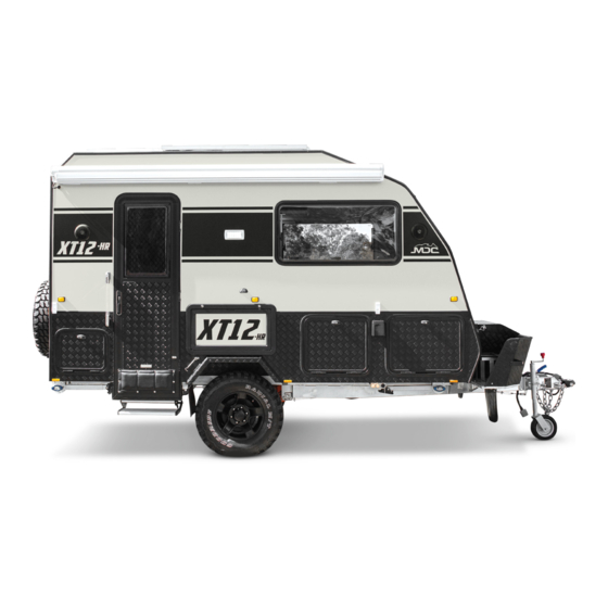
- Page 1 XT12HR OVERLAND Travel Trailer OWNER’S MANUAL U.S.A. EDITION: 2021 - Version 1 www.mdcusa.com Phone: 833 632 8721 Copyright © MDC Caravans and Campers INC 2021 All Rights Reserved...
- Page 2 Your use of this Owner’s Manual does not constitute any right or license for you to use MDC’s or any other party’s service marks or trademarks, without the prior written permission of MDC or the applicable party.
- Page 3 TIRE SIZE: DEALER PH: DISCLAIMER: By receiving this handbook, you confirm there you have read and agree to all the terms and conditions and understood the use and maintenance care of MDC Campers and Caravans Inc. www.mdcusa.com Ph: 833 632 8721...
-
Page 4: Table Of Contents
Tire Safety Information ..............11 Dangerous Gases ..............23 Steps for Determining Correct Load Limit - Trailer ..11 MDC Contract Details and Stores ........23 Trailers 10,000 Pounds GVWR or Less ......11 Specifications .................24 Steps for Determining Load Limit - TOW VEHICLE ...11 Using Your Trailer .................25... - Page 5 Protection of Finishes ............40 Access door ..............52 Corrosion Protection ............40 Removing the access door ........53 Solar Panels ................41 Closing the access door ..........53 Sealants ...................41 Starting the Appliance ..........54 Trailer Body Maintenance ............41 Inspections before each use ........54 Winterizing the Trailer ............41 Operating Procedures .............
-
Page 6: General Safety Information
MDC trailers are manufactured using many third party supplied products which have separate manuals. These manual must be read in conjunction with this document and all instructions followed. If your trailer does not have additional... -
Page 7: Reporting Safety Defects
If you believe that your vehicle has a defect that could cause a crash or could cause injury or death, you should immediately inform the National Highway Traffic Safety Administration (NHTSA) in addition to notifying MDC Caravans and Campers INC. -
Page 8: Terminology & Abbreviations
Terminology & Abbreviations Dry Weight: The total weight of the trailer (load on tires plus coupling load) with all options and fittings as supplied by the manufacturer, with empty water tanks, excluding fluids not essential for operation on public roads, and without luggage or personal effects. -
Page 9: Secondary Escape
Positive toe, or toe in, is the front of the wheel pointing towards the centerline of the vehicle. Toe can be measured in linear units, at the front or rear of the tire, or as an angular deflection. In the case of MDC products, the “toe in”... -
Page 10: Warning
Caravan to sway and/or roll excessively left and right. The industry optimum ball weight on a caravan is between 9 and 11% of the total trailer weight. MDC trailers fit into this category and 10% should be used as the starting point. -
Page 11: Tire Safety Information
Tire Safety Information This section of the User Manual contains tire safety information as required by 49 CFR 575.6. Steps for Determining Correct Load Limit - Trailer Trailers 10,000 Pounds GVWR or Less Locate the statement “The weight of cargo should never exceed XXX kg or XXX lbs” on your vehicles placard. -
Page 12: Tire Safety - Everything Rides On It
Tire Safety - Everything Rides on it The National Traffic Safety Administration (NHTSA) has published a brochure (DOT HS 809 361) that discusses all aspects of Tire Safety, as required by CFR 575.6. This brochure is reproduced in part below. It can be obtained and downloaded from NHTSA, free of charge, from the following web site: http://www.nhtsa.dot.gov/cars/rules/ TireSafety/ridesonit/tires_index.html Studies of tire safety show that maintaining proper tire pressure, observing tire and vehicle load limits (not... -
Page 13: Checking Tire Pressure
Checking Tire Pressure It is important to check your vehicle’s tire pressure at least once a month for the following reasons: • Most tires may naturally lose air over time. • Tires can lose air suddenly if you drive over a pothole or other object or if you strike the curb when parking. -
Page 14: Tire Repair
Tire Repair The proper repair of a punctured tire requires a plug for the hole and a patch for the area inside the tire that surrounds the puncture hole. Punctures through the tread can be repaired if they are not too large, but punctures to the sidewall should not be repaired. -
Page 15: Treadwear Number Utqgs Information
The “M+S” or “M/S” indicates that the tire has some mud and snow capability. Most radial tires have these markings; hence, they have some mud and snow capability. U.S DOT Tire Identification Number This begins with the letters “DOT” and indicates that the tire meets all federal standards. The next two numbers or letters are the plant code where it was manufactured, and the last four numbers represent the week and year the tire was built. -
Page 16: Additional Information On Light Truck Tires
Additional Information on Light Truck Tires Please refer to the following diagram. Tires for light trucks have other markings besides those found on the sidewalls of passenger tires. The “LT” indicates the tire is for light trucks or trailers. An “ST” is an indication the tire is for trailer use only. Max. -
Page 17: Propane Safety
Propane Safety Appliances in your trailer are fueled with propane. Propane is heavier than air which will allow it to pool in some areas creating an explosion risk. It is mandatory to follow all manufacturer guidelines in the use of propane appliances. DANGER •... -
Page 18: Propane Cylinder Safety
Propane Cylinder Safety WARNING DO NOT place propane cylinders inside the vehicle. Propane cylinders are equipped with safety devices that relieve excessive pressure by discharging propane to the atmosphere. Propane gas is highly flammable and can lead to a fire or explosion and result in death or serious injury. -
Page 19: Gas Appliance Safety
Gas Appliance Safety DANGER DO NOT use gas cooking appliances for comfort heating. This can lead to carbon monoxide poisoning, which can lead to death or serious injury WARNING Gas cooking appliances need fresh air for safe operation. Before operation: Open vents or windows slightly or turn on exhaust fan prior to using cooking appliance. -
Page 20: Electrical Safety
Electrical Safety WARNING Failure To Follow These Instructions May Result In Death Or Serious Injury! • When working with electrical equipment or lead acid batteries, have someone nearby in case of an emergency. • Study and follow all the manufacturer’s specific precautions when using and servicing the battery and connected appliances. -
Page 21: General Safety
General Safety Brakes WARNING Your trailer brakes must be maintained and adjusted to operate correctly at all times. Failure to maintain and adjust brakes as outlined in the maintenance schedule may result in a failure causing death or serious injury. Brake Controller Your trailer is fitted with drum type electric brakes. -
Page 22: Jacking Your Trailer
Jacking Your Trailer Your trailer is fitted with purpose built jacking points and from January 2021 supplied with a suitable jack. An appropriately rated bottle jack is an acceptable alternative, however when using the jacking point beneath the trailing arm ensure the jack is of a retracted height that will fit under the jacking point when the tire is deflated. A suitably rated “High Lift”... -
Page 23: Dangerous Gases
• Never cover permanent vents in the roof or pop top skirt or annex. • When using a generator, the generator must be placed where carbon monoxide fumes cannot enter the trailer. Carbon Monoxide Detector MDC USA Contact Details and Stores CALIFORNIA ARIZONA Los Angeles 3908 East Broadway Rd. -
Page 24: Specifications
SPECIFICATIONS BERTH SIZE 18’4” x 7’6” x 9’10” STYLE 16’ hybrid overland caravan DRY HITCH WEIGHT 375 lbs DRY WEIGHT 4034 lbs GVWR 6172 lbs FRAME Hot Dipped Galvanized Steel BODY CONSTRUCTION Aluminum composite panel STONE PROTECTION Included with stone tamer mudflaps SUSPENSION Independent trailing arm with 4x shock absorbers and coil springs WHEELS &... -
Page 25: Using Your Trailer
Using Your Trailer NOTICE Instructions below are for your safety and the avoidance of accidental damage to the trailer through misuse. Follow all directions given in this manual and the manuals for third party products installed. The manufacturer has produced product specific video content for tutorial purposes, to assist in the correct setup and use. -
Page 26: Connecting The Hitch
Connecting the Hitch Here is a short guide on how to safely use your coupling to couple and uncouple the trailer from the towing vehicle. Make sure the handbrake is applied prior to coupling and uncoupling. www.mdcusa.com Ph: 833 632 8721... - Page 27 Make sure the dust cap is securely connected to the bump cover. This is done by locating the rear lip on the dust cap onto the groove of the bump cover and then pushing it in a downward motion until the dust cover is secure (there should be a slight click when it has been assembled correctly) Test if the dust cover is connected to the bump cover by applying a slight upward force to the dust cover, it shouldn’t separate.
- Page 28 Coupling STEP 1 Push down the button (1) and push the locking mechanism back (2). When the locking mechanism (2) is all the way back, release the button (1) locking the plate in place STEP 2 Offer up the tow pin to the coupling making sure the tow pin cover is removed and there is no visible debris on it. Locking plate should be in unlocked position as shown.
- Page 29 STEP 3 Make sure the tow pin is seated inside the universal and the tow pin top is sticking out of the locking mechanism (see below). Press the button (1) to release the locking mechanism there will be an audible locking noise at which point the mechanism will return to the initial position as shown in step 1.
- Page 30 Uncoupling STEP 1 Push down the button 1 and push the locking mechanism back 2. When the locking mechanism is all the way back release the button while holding the mechanism to ensure it does not spring back to the locked position. STEP 2 Lift the coupling up off the tow pin.
-
Page 31: Connecting Wiring
Connecting Wiring When connecting ensure the electric cables to your tow vehicle cannot drag on the road or foul the coupling. If necessary, use zip ties or like keep them neat and safe from damage. Connecting the Safety Chains Chains should be crossed over and connected with suitable rated shackles. Ensure they are connected in a way to prevent them dragging on the road but not too tight as to restrict the articulation of the vehicle and trailer combination. -
Page 32: Connecting The Breakaway
Connecting the Breakaway The breakaway lanyard is connected to a simple switch on the drawbar. When connecting the lanyard to the tow vehicle it should be connected to a solid part of the vehicle. Do not incorporate its connection with the safety chains Breakaway Switch Lanyard Connection WARNING... -
Page 33: Loading Your Trailer
Loading Your Trailer Loading your trailer can have an effect on the overall handling of the trailer and tow vehicle combination. Loading affects tongue weight and balance which must be taken into consideration. • DO NOT exceed the Gross Vehicle Weight Rating (GVWR) or the stated cargo capacity which can be found on the trailers tire placard or load carrying capacity label. -
Page 34: Operating Trailer Features
Operating Trailer Features This sections covers details on using the common features on your trailer correctly. Stabilizer Legs The stabilizer legs are fitted to make the trailer stable when occupied. Important things to not are: • Always try to set the stabilizers up in a vertical position, 90 degrees to the chassis as shown in figure below. - Page 35 When kitchen is extended fit the support leg into its receiver (Fig: 3) Extend support leg and secure locking screw (Fig: 3a) Fig: 3 Fig: 3a Once you connect your gas bottle you can connect the kitchen gas hose to the bayonet connection provided. (Fig:5) Fig: 5 www.mdcusa.com Ph: 833 632 8721...
-
Page 36: 12 Volt Electrical System
12 Volt Electrical System Control Panel Control Panel Main Rotary Switch: This is used to switch on or isolate the entire 12 volt system. Circuit Breakers: The round rubber capped Circuit breakers are resettable. To reset the circuit push in the rubber cap. -
Page 37: Towing Your Trailer
Towing Your Trailer Driving dynamics change considerably when towing a trailer. Many facets of driving need to be modified when towing for your safety and that of other road users. Important points you must know, understand, and adhere to are: •... -
Page 38: Correct Wiring Of Tow Vehicle
Correct Wiring of Tow Vehicle Vehicle with or without smart alternator: The Anderson plug can be connected to the tow vehicle start battery on the vehicle and should include the following to protect the start battery. 50 amp relay to stop power supply when vehicle is not running. 50 amp fuse or circuit breaker at the battery www.mdcusa.com Ph: 833 632 8721... -
Page 39: Choosing A Camp Site
Choosing a Camp Site When choosing a campsite always consider the following: • Choose a flat even area when possible. • Never camp under trees with a risk of branches falling. • Camping in shade will reduce the performance of solar power charging. •... -
Page 40: Care And Maintenance Of The Trailer
Care and Maintenance of the Trailer Protection of Finishes Paint The paint coatings on your trailer are no different to that of your car in that they need regular care and maintenance. Rubber seals and applied sealants on trailers can shed polymers and pigments that can stain paint finishes if your trailer isn’t washed regularly. -
Page 41: Solar Panels
Solar Panels Accumulated dirt and soiling can affect the performance of the solar panels. Panels should be cleaned as necessary to prevent this. Sealants around solar panel mounts should be checked annually to ensure they are in good condition. Sealants Roof sealants should be inspected every 6 months for condition. -
Page 42: Mechanical Maintenance
Mechanical Maintenance WARNING WARNING – Failing to maintain your trailer adequately COULD result in severe personal injury or death if the warning is ignored. Maintain according to the maintenance schedule as a minimum requirement. Wheels and Tires Tires should be checked for damage prior to each trip. Inspect for adequate tread depth and any damage particularly to sidewalls. -
Page 43: Magnets
It is important to replace both shoes on each brake and both brakes of the same axle. This is necessary to retain the “balance” of your brakes. Be sure to replace your shoes only with genuine MDC parts available from our outlets. -
Page 44: Suspension
Suspension Suspension maintenance should be done as per the schedule contained in this booklet. Regular lubrication and inspection are critical, and the grease points are indicated below. Regular checks of the torque on the trailing arm bolts indicated will prolong correct wheel alignment. Trailing arm suspension should not be reversed up gutters and obstructions in a heavy matter. -
Page 45: Hitch
Adjuster Early Models To adjust the handbrake cable tension release locknuts A, B and C in the diagram Handbrake Adjuster 1 below. To tighten the handbrake cable, turn the adjuster wheel D in a clockwise direction. Once adjusted re-tighten lock nuts and test. -
Page 46: Plumbing And Toilet
Aqua Kem Blue or Aqua Kem Green for better environmental performance. Cleaning Cassette Tank: “Cassette Tank Cleaner” is the recommended product for this application. Flush Water Tank: Only suitable for MDC models that have a toilet flush tank. Thetford recommended “Aqua Rinse” ***Do not add to main water tank! *** Grey Water Tank: Tank Freshener www.mdcusa.com... -
Page 47: Truma Aquago Hot Water System
Truma AquaGo Hot Water System The Manufacturers Operation Manual States: Safety symbols and signal words This is the safety alert symbol. This symbol alerts you to potential hazards that can kill or hurt you and others. DANGER! indicates a hazardous situation which, if not avoided, will result in death or serious injury. WARNING! indicates a hazardous situation which, if not avoided, could result in death or serious injury. -
Page 48: Safe Operation
Safe operation • Use with LP gas (propane) only. Butane or any mixtures containing more than 10% butane must not be used. LP tanks must be filled by a qualified gas supplier only. • The nominal gas system pressure must be 10.5 in. wc. •... -
Page 49: Safe Handling Of Malfunctions
Safe handling of malfunctions • Switch OFF the gas supply and the appliance: if anything seems to be out of the ordinary. if you smell gas. DANGER! • Fire / explosion if you attempt to use an appliance that has been damaged by flooding or if the vehicle has been involved in an accident. -
Page 50: Operating Instructions
Operating Instructions Read and follow the “Consumer Safety Information” before operating the appliance. WARNING Scalding injuries caused by hot water! Water temperatures over 127ºF (52ºC) can cause severe burns or scalding and in extreme cases even death. • Before using the hot water faucet or using the shower, allow the hot water to run until the water temperature no longer increases. -
Page 51: Pressure Relief Valve
Pressure relief valve WARNING Scalding injury from hot water and/or tampering with the pressure relief valve! • Never actuate the pressure relief valve as long as the appliance is still hot. • Do not place a plug or reducing coupling on the outlet part of the valve. •... -
Page 52: Access Door
Access door Opening the access door Turn the turn lock counter-clockwise into the vertical position. • The access door can be opened in two different positions: Position ‘1’ is the maximum opening width for switching the appliance on or off. Position ‘2’... -
Page 53: Removing The Access Door
Removing the access door Open the access door to Position ‘2’. Move the access door upwards to remove it. Closing the access door NOTICE Damage to the access door and the RV if the access door is not closed properly! •... -
Page 54: Starting The Appliance
Starting The Appliance WARNING Danger of over-temperature and toxic exhaust gases! • Use with LP gas (propane) only. Butane or any mixtures containing more than 10 % butane must not be used. • Keep the air inlet and exhaust gas outlet free of obstructions. Do not lean any objects against the water heater’s access door or place any foreign objects within 2 feet (61 cm) of the access door. -
Page 55: Operating Procedures
Operating Procedures NOTICE Risk of damage in frost conditions. In frost conditions, ambient temperatures below 39 °F (4 °C), there is a risk that water in pipes, faucets and appliances could freeze. This can cause considerable damage. • Before you fill water into appliances and parts that transport water, you must heat the installation area sufficiently so that the water cannot freeze. - Page 56 • There may be a variation between the temperature delivered from the appliance and the temperature at the faucet due to water conditions or the length of pipe from the appliance. • The presence of a flow restricter in the hot water line may Limit the water flow. How to use hot water: •...
-
Page 57: Operating Modes (Control Panel)
Operating modes (control panel) AquaGo comfort / AquaGo comfort plus A control panel to select the operating mode (included with the delivery from serial number DLE60X(X)27100000). With the rotary switch (Fig. 9) you can choose between the following operating modes: Sign Operating mode/ Description The appliance is now running in energy-saving mode. -
Page 58: Operation In Frost Conditions
Switching OFF the appliance 1. AquaGo comfort / AquaGo comfort plus Set the control panel to “Off”. 2. Open the access door (refer to “Opening the access door” on page 52). 3. Switch off the appliance at the POWER switch (Fig. 8). - The green Power-ON LED 1 (Fig. -
Page 59: Winterizing
While driving (or if there is no gas supply), to -4 °F (-20 °C) NOTICE! • Gas must not be used for heating while the vehicle is in motion. Ask your dealer / vehicle manufacturer about options for heating your RV while driving. •... -
Page 60: Winterizing The Rv With A Winterizing Fluid
Winterizing the RV with a winterizing fluid • Winterizing the RV with a winterizing fluid is only possible with an installed bypass kit (not in scope of delivery) • Refer to “Connection diagrams” in manufacturers booklet for all letters referred to in the following description. -
Page 61: Draining The Water And Cleaning The Water Inlet Filter
Maintenance Repairs must be performed by a certified service technician. Truma recommends that the appliance be serviced annually by a certified service technician. Verify proper operation after servicing. WARNING High temperatures or repair attempts while the gas supply is turned on may result in scalding injuries! •... - Page 62 CAUTION Injuries caused by the Easy Drain Lever! When the Easy Drain Lever is folded out, it protrudes beyond the side wall of the vehicle. • When walking past or stooping down, make sure that you and others have sufficient distance. 7.
-
Page 63: Decalcification
Decalcification NOTICE Risk of damage in frost conditions. In frost conditions, ambient temperatures below 39 °F (4 °C), there is a risk that water in pipes, faucets and appliances could freeze. This can cause considerable damage. • Do not decalcify the appliance in frost conditions. Decalcification Frequency Lime scale occurs especially as a result of precipitation from “hard”... - Page 64 Decalcification (models with control panel) AquaGo comfort / AquaGo comfort plus with control panel (included with delivery). An integrated water consumption meter recognizes (after hot water consumption of approx. 1585 gallons / 6000 l) that decalcification is necessary. The assumed water hardness is “hard” and cannot be changed. The yellow status LED 3 (Fig.
- Page 65 a) Preparing for decalcification For safety reasons, once the decalcification process has started it must not be stopped until the system has been rinsed (see process f). All operating modes of the appliance are blocked until decalcification has been completed. Tasks within the RV •...
- Page 66 c) Introducing the decalcification agent Tasks outside the RV WARNING Irritation of skin and eyes in case of contact with decalcification agent. Wear protective gloves, eye protection and face protection to avoid contact. • Fill the water inlet filter with 6 AquaGo decalcification tablets (content of one blister pack). •...
- Page 67 e) Starting decalcification Tasks within the RV • Set the control panel to “Clean”. If decalcification does not start, switch the appliance on at the POWER switch. • Decalcification takes about 3 hours (during this time, you do not have to do anything). •...
- Page 68 g) Filling the water system Tasks within the RV • Turn on fresh water supply or switch on water pump. Fill the water system. Open all water-release points, e.g., hot water faucets, showers, toilets . Once water flows evenly, the water system is vented. Close the water-release points.
- Page 69 Troubleshooting Problem Potential Cause Resolution No hot water at Gas supply is turned off or Check and/or turn on gas supply. the faucet interrupted. Gas tank is empty Refill/replace the gas tank. The appliance is switched off. Switch on the appliance according to instructions (refer to “Operating procedures”...
- Page 70 AquaGo comfort / AquaGo comfort plus Problem Potential Cause Resolution The yellow status Power swtich is OFF Switch ON the appliance at the POWER switch. LED 3 is off al- Power supply to the appliance is Switch on the power supply to the appliance. though an oper- switched off ating mode was...
-
Page 71: Water Pump
Water Pump The pump when switched on is activated by the release of pressure at the tap and will pump water continuously until the tap is turned off and pressure restored. Should the pumps activate while the taps is turned off this could indicate a leak and require investigation and rectification. -
Page 72: Furnace
Furnace Not standard on this model Dometic DFSD 12111 Furnace Introduction: The following instructions are an extract from the Operation Manual published by the manufacturer Dometic Corporation. These instructions are a guide to operation of the furnace only. The manufacturers Operation Manual included with the product MUST be read in its entirety before operating this appliance. - Page 73 WARNING ELECTRICAL SHOCK HAZARD Failure to obey the following warnings could result in property damage, serious injury or death: • Furnaces with 12 VDC connection are for low-voltage battery or direct current only. Do NOT connect to 120 or 240 VAC. This Furnace is designed for negative ground 12 VDC only.
-
Page 74: Operation
Operation WARNING FIRE OR EXPLOSIVE HAZARD Failure to obey the following warnings could result in property damage, serious injury or death: • This Furnace does not have a pilot. It is equipped with an ignition device that automatically lights the burner. Do NOT try to light the burner by hand. -
Page 75: Turning Off The Furnace
NOTICE If the Furnace will not operate, follow the instructions for “B. Turning Off The Furnace” and call a qualified service technician. B. Turning Off The Furnace • Set the thermostat to the lowest setting, then turn to the OFF position. •... -
Page 76: Schematics & Part Numbers
MJFCX003 14mm Wheels Stud YHJL110 14mm Wheel Nut YZCQ029 M38 Castle Nut M38 Metric LGPJ002 90mm Bearing Dust Cap (3 35 /64”) MDC Specific CSWH001 Wheel Bearing (Timken) 25590 Bearing Race 25590 Bearing Seal Metric 55 x 85 x 12mm 2 ¹¹/64”... -
Page 77: Electrical Diagram
Electrical Diagram www.mdcusa.com Ph: 833 632 8721... -
Page 78: Battery Care
Battery Care Your trailer is fitted with 100Ah AGM Batteries. Storage type batteries require periodical maintenance to perform at their peak and extend their service life. The following is an outline on how to gain the best performance and lifecycle from the battery fitted in your camper: •... -
Page 79: Charging System - Bm Pro
Charging System - BM Pro Your trailer is fitted with a BM PRO Battery Plus 35SR management unit. This unit controls all power input to the trailer. The unit is a multi-stage charger for solar, vehicle and shore power input. Warning Failure To Follow These Instructions May Result In Death Or Serious Injury! Batteries are electrically live and must be treated with extreme caution. -
Page 80: Batteryplus Trouble Shooting
Batteryplus Trouble Shooting BATTERYPLUS35-II OPERATIONAL STATUS INDICATOR Table displays the operational status of the BatteryPlus35-II, as shown by the colored flash of the LED Status Indicator on the BatteryPlus35-II LED FLASH KEY AC Charging Solid Color Low Battery Voltage Flash Color LFG Mode No Battery SI Solar Charging LED Off... -
Page 81: Hub Assembly
Hub Assembly www.mdcusa.com Ph: 833 632 8721... -
Page 82: Trailing Arms And Bushes
Trailing Arms and Bushes www.mdcusa.com Ph: 833 632 8721... -
Page 83: Service Record And Schedule
Service Record and Schedule 300 miles FIRST SERVICE CHECKED • Check hitch bolts to 90Nm/66ft lb. Hitch • Lubricate. Handbrake • Inspect and adjust handbrake. • Inspect and adjust brakes. Check bearings are well greased and crown Brakes & Bearings nut is correctly tightened. - Page 84 Every 6 MONTHS / 3,000 miles SERVICE CHECKED • Check hitch bolts to 90Nm/66ft lb. Hitch .• Lubricate. Handbrake • Check cable and adjust if necessary. Hand winch • Check brake function and webbing. • Torque bolts to 190Nm/140ft lb. •...
- Page 85 12 MONTHS / 6,000 miles SERVICE CHECKED Chassis and Suspension • Check hitch bolts to 90Nm/66ft lb. Hitch • Lubricate. Jockey Wheel • Inspect for condition and operation. • Check for correct operation. Breakaway • Inspect lanyard and clip. Drawbar •...
- Page 86 Caravan Body Hatches & Doors • Check and lubricate locks. • Check condition and correct latch/lock adjustment for correct Seals 30-50% compression. • Inspect joint sealants inside and out. Body • Ensuite joints checked for damage and adhesion. • Inspect for soft spots on floor. General fixings •...
- Page 87 18 MONTHS / 9,000 miles SERVICE CHECKED • Check hitch bolts to 90Nm/66ft lb. Hitch • Lubricate. Handbrake • Check cable and adjust if necessary. Hand winch • Check brake function and webbing. • Lubricate and check bushes for excess movement. Suspension •...
- Page 88 24 MONTHS / 12,000 miles SERVICE CHECKED Chassis and Suspension • Check hitch bolts to 90Nm/66ft lb. Hitch • Lubricate. Jockey Wheel • Inspect for condition and operation. • Check for correct operation. Breakaway • Inspect lanyard and clip. Drawbar •...
- Page 89 Caravan Body Hatches & Doors • Check and lubricate locks. • Check condition and correct latch/lock adjustment for correct Seals 30-50% compression. • Inspect joint sealants inside and out. Body • Ensuite joints checked for damage and adhesion. • Inspect for soft spots on floor. General fixings •...
- Page 90 30 MONTHS / 15,000 miles SERVICE CHECKED • Check hitch bolts to 90Nm/66ft lb Hitch • Lubricate Handbrake • Check cable and adjust if necessary. Hand winch • Check brake function and webbing. • Lubricate and check bushes for excess movement. Suspension •...
- Page 91 36 MONTHS / 18,000 miles SERVICE CHECKED Chassis and Suspension • Check hitch bolts to 90Nm/66ft lb. Hitch • Lubricate. Jockey Wheel • Inspect for condition and operation. • Check for correct operation. Breakaway • Inspect lanyard and clip. Drawbar •...
- Page 92 Caravan Body Hatches & Doors • Check and lubricate locks. • Check condition and correct latch/lock adjustment for correct Seals 30-50% compression. • Inspect joint sealants inside and out. Body • Ensuite joints checked for damage and adhesion. • Inspect for soft spots on floor. General fixings •...
- Page 93 42 MONTHS / 21,000 miles SERVICE CHECKED • Check hitch bolts to 90Nm/66ft lb Hitch • Lubricate Handbrake • Check cable and adjust if necessary. Hand winch • Check brake function and webbing. • Lubricate and check bushes for excess movement. Suspension •...
- Page 94 48 MONTHS / 24,000 miles SERVICE CHECKED Chassis and Suspension • Check hitch bolts to 90Nm/66ft lb. Hitch • Lubricate. Jockey Wheel • Inspect for condition and operation. • Check for correct operation. Breakaway • Inspect lanyard and clip. Drawbar •...
- Page 95 Caravan Body Hatches & Doors • Check and lubricate locks. • Check condition and correct latch/lock adjustment for correct Seals 30-50% compression. • Inspect joint sealants inside and out. Body • Ensuite joints checked for damage and adhesion. • Inspect for soft spots on floor. General fixings •...
- Page 96 54 MONTHS / 27,000 miles SERVICE CHECKED • Check hitch bolts to 90Nm/66ft lb Hitch • Lubricate Handbrake • Check cable and adjust if necessary. Hand winch • Check brake function and webbing. • Lubricate and check bushes for excess movement. Suspension •...
- Page 97 60 MONTHS / 30,000 miles SERVICE CHECKED Chassis and Suspension • Check hitch bolts to 90Nm/66ft lb. Hitch • Lubricate. Jockey Wheel • Inspect for condition and operation. • Check for correct operation. Breakaway • Inspect lanyard and clip. Drawbar •...
- Page 98 Caravan Body Hatches & Doors • Check and lubricate locks. • Check condition and correct latch/lock adjustment for correct Seals 30-50% compression. • Inspect joint sealants inside and out. Body • Ensuite joints checked for damage and adhesion. • Inspect for soft spots on floor. General fixings •...
- Page 99 66 MONTHS / 33,000 mile SERVICE CHECKED • Check hitch bolts to 90Nm/66ft lb Hitch • Lubricate Handbrake • Check cable and adjust if necessary. Hand winch • Check brake function and webbing. • Lubricate and check bushes for excess movement. Suspension •...
- Page 100 72 MONTHS / 36,000 miles SERVICE CHECKED Chassis and Suspension • Check hitch bolts to 90Nm/66ft lb. Hitch • Lubricate. Jockey Wheel • Inspect for condition and operation. • Check for correct operation. Breakaway • Inspect lanyard and clip. Drawbar •...
- Page 101 Caravan Body Hatches & Doors • Check and lubricate locks. • Check condition and correct latch/lock adjustment for correct Seals 30-50% compression. • Inspect joint sealants inside and out. Body • Ensuite joints checked for damage and adhesion. • Inspect for soft spots on floor. General fixings •...
- Page 102 78 MONTHS / 39,000 mile SERVICE CHECKED • Check hitch bolts to 90Nm/66ft lb Hitch • Lubricate Handbrake • Check cable and adjust if necessary. Hand winch • Check brake function and webbing. • Lubricate and check bushes for excess movement. Suspension •...
- Page 103 84 MONTHS / 42,000 miles SERVICE CHECKED Chassis and Suspension • Check hitch bolts to 90Nm/66ft lb. Hitch • Lubricate. Jockey Wheel • Inspect for condition and operation. • Check for correct operation. Breakaway • Inspect lanyard and clip. Drawbar •...
- Page 104 Caravan Body Hatches & Doors • Check and lubricate locks. • Check condition and correct latch/lock adjustment for correct Seals 30-50% compression. • Inspect joint sealants inside and out. Body • Ensuite joints checked for damage and adhesion. • Inspect for soft spots on floor. General fixings •...
-
Page 105: Travel Record
Travel Record Your caravan service record booklet and logbook will help you keep track of miles travels and service records. Trip Name Date Miles Start Miles Finish Cumulative Miles www.mdcusa.com Ph: 833 632 8721... - Page 106 Trip Name Date Miles Start Miles Finish Cumulative Miles www.mdcusa.com Ph: 833 632 8721...
-
Page 107: Warranty Policy
Notwithstanding the foregoing or anything herein to the contrary, you are advised that certain states may provide you with different or additional rights OR REMEDIES with respect to your purchase of any Product from MDC. As such, these Limited Warranties, and any disclaimer or limitation stated herein, are subject to ANY APPLICABLE STATE OR FEDERAL LAW AND SHALL APPLY ONLY TO the maximum extent permitted by applicable law. - Page 108 LIMITED WARRANTY FOR TENTS Tents are guaranteed by MDC to be in new condition and without flaws or defects at the time of purchase by you, general wear and tear excepted and excluding any other Limited Warranty exclusion as set forth herein.
- Page 109 FACTORY SECONDS, EX-DEMONSTRATION AND DAMAGED GOODS From time to time, MDC may offer for sale items deemed to be “factory seconds”, “ex-demonstration”, “used” or “damaged”. Products sold as “factory seconds”, “ex-demonstration” or “damaged” items are sold on an “as is” basis without any warranty of any kind.
- Page 110 To the maximum extent permitted by applicable law and unless specifically stated in writing at the time of auction, any Products sold at auction by or on behalf of MDC shall carry no warranty, whether express, implied or statutory, and shall be sold “as is.”...
-
Page 111: Guide To Video Tutorials
Guide to Video Library Walkthrough Setup Tutorial View this video for an overall instruction on operating View this video for correct setup procedure Scan code of go to the product Scan code of go to https://youtu.be/8iqrYW1xQ-M https://youtu.be/s8YAiMb9aIw Pack Down Video Tutorial View this video to pack down your caravan Scan code of go to https://youtu.be/R3iK6jz_2Vg...
Need help?
Do you have a question about the XT12HR and is the answer not in the manual?
Questions and answers