Table of Contents
Advertisement
Available languages
Available languages
Quick Links
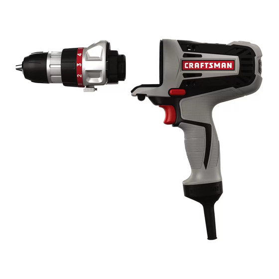
Operator's Manual
Corded Power Unit &
Drill Attachment
Model: 35592
cautiOn: Read, understand and follow
all Safety Rules and Operating Instructions
in this manual before using this product.
Sears Brands Management Corporation,
Hoffman Estates, IL 60179 U.S.A.
See the full line of Craftsman
at craftsman.com
Part No. 90597924
products
®
• Safety
• OperatiOn
• Maintenance
• trOubleShOOting
• eSpañOl pg. 9
May 13
Advertisement
Table of Contents

Related Manuals for Craftsman Bolt-On 35592


Summary of Contents for Craftsman Bolt-On 35592
- Page 1 • Safety • OperatiOn Sears Brands Management Corporation, Hoffman Estates, IL 60179 U.S.A. • Maintenance • trOubleShOOting See the full line of Craftsman products • eSpañOl pg. 9 ® at craftsman.com Part No. 90597924 May 13...
-
Page 2: Safety Alert Symbol
CRAfTSMAN ONe yeAR lIMITeD WARRANTy fOR ONe yeAR from the date of purchase, this power tool is warranted against defects in material or workmanship. With proof of purchase, a defective product will be replaced free of charge. for warranty coverage details to obtain free replacement, visit the web site: www.craftsman.com... -
Page 3: Electrical Safety
2) eleCTRICAl SAfeTy a) Power tool plugs must match the outlet. Never modify the plug in any way. Do not use any adapter plugs with earthed (grounded) power tools. Unmodified plugs and matching outlets will reduce risk of electric shock. b) Avoid body contact with earthed or grounded surfaces such as pipes, radiators, ranges and refrigerators. -
Page 4: Safety Equipment
g) Use the power tool, accessories and tool bits, etc. in accordance with these instructions, taking into account the working conditions and the work to be performed. Use of the power tool for operations different from those intended could result in a hazardous situation. 5) SeRvICe a) have your power tool serviced by a qualified repair person using only identical replacement parts. -
Page 5: Parts And Features
When using an extension cord, be sure to Minimum Gauge for Cord Sets use one heavy enough to carry the current volts Total length of Cord in feet 120V 0-25 26-50 51-100 101-150 your product will draw. An undersized (0-7,6m) (7,6-15,2m) (15,2-30,4m) (30,4-45,7m) cord will cause a drop in line voltage 240V 0-50 51-100 101-200 201-300 resulting in loss of power and overheating. (0-15,2m) (15,2-30,4m) (30,4-60,9m) (60,9-91,4m) The following table shows the correct Ampere Rating More Not more American Wire Gauge size to use depending on cord length and Than Than... - Page 6 • To select reverse, depress the forward/reverse control button to the right (as viewed from rear of tool). NOTe: When changing the position of the control button, be sure the trigger is released. INSTAllING AND ReMOvING TOOl ATTAChMeNTS - fIGURe A WARNING Shock hazard. Under no circumstances should this product be used near water. WARNING: Burn hazard. Moving parts within the Power Unit become hot during use. Avoid contact with moving parts within Power Unit when removing and installing accessories.
- Page 7 SCReW DRIvING • Always use the correct type and size of screwdriver bit. • If screws are difficult to tighten, try applying a small amount of washing liquid or soap as a lubricant. • Always hold the tool and screwdriver bit in a straight line with the screw. • For driving fasteners, the reversing button should be pushed to the left (as viewed from rear of tool). Use reverse (button pushed to the right) for removing fasteners. When moving from forward to reverse, or vice versa, always release the trigger switch first.
-
Page 8: Troubleshooting
DRIllING IN WOOD Holes in wood can be made with the same twist drill bits used for metal or with spade bits. These bits should be sharp and should be pulled out frequently when drilling to clear chips from the flutes. DRIllING IN MeTAl Use a cutting lubricant when drilling metals. The exceptions are cast iron and brass which should be drilled dry. The cutting lubricants that work best are sulfurized cutting oil or lard oil. MAINTeNANCe Use only mild soap and damp cloth to clean the tool. Never let any liquid get inside the tool; never immerse any part of the tool into a liquid. iMpOrtant: To assure product SAFETY and RELIABILITY, repairs, maintenance, and adjustment a qualified service dealer or other (other than those listed in this manual) should be performed by qualified service personnel ACCeSSORIeS WARNING:... - Page 9 UN AÑO De GARANTÍA lIMITADA PARA lOS PRODUCTOS CRAfTSMAN este producto está garantizado contra defectos de material o mano de obra DURANTe UN AÑO a partir de la fecha de compra. Se reemplazará un producto defectuoso sin cargo al presentar el comprobante de compra.
- Page 10 b) No opere herramientas eléctricas en atmósferas explosivas, como ambientes donde se encuentran líquidos, gases o polvo inflamables. Las herramientas eléctricas originan chispas que pueden encender el polvo o los vapores. c) Mantenga a los niños y espectadores alejados de la herramienta eléctrica en funcionamiento.
-
Page 11: Normas De Seguridad Específicas
herramienta eléctrica antes de realizar ajustes, cambiar accesorios o almacenar herramientas eléctricas. Estas medidas de seguridad preventivas reducen el riesgo de encender la herramienta eléctrica en forma accidental. d) Guarde las herramientas eléctricas que no están en uso fuera del alcance de los niños y no permite que otras personas no familiarizadas con ella o con estas instrucciones operen la herramienta. -
Page 12: Lea Todas Las Instrucciones
SÍMBOlOS • La etiqueta de su herramienta puede incluir los siguientes símbolos. Los símbolos y sus definiciones son los siguientes: V ....voltios A ....amperios Hz ....hertz W ....vatios min ....minutos ....corriente alterna n o ....no velocidad sin carga .... corriente directa ....Construcción Clase I ....terminal a tierra (mis à la terre) ....Construcción de clase II .....simbolo de alerta .../min .. - Page 13 INSTRUCCIONeS De OPeRACIÓN: UNIDAD MOTRIZ INTeRRUPTOR De GATIllO INTeRRUPTOR DeSlIZANTe De AvANCe/ReveRSA El interruptor deslizante de avance/reversa (2) de la unidad motriz (1) se utiliza para controlar la dirección de giro del mandril (6): avance para instalar tornillos y reversa para quitar tornillos. Este se encuentra encima del gatillo de velocidad variable (3). Para revertir el motor, PRIMERO suelte el gatillo, luego empuje el interruptor deslizante hacia el lado derecho de la herramienta (visto desde atrás). Después de cualquier operación en reversa, devuelva la palanca a la posición de avance. Nunca cambie la dirección de rotación con el motor en funcionamiento. • El taladro se ENCIENDE y APAGA tirando y liberando el interruptor disparador. Cuanto más se oprima al disparador, mayor será la velocidad del taladro. • El botón de control de avance/reversa determina la dirección de la herramienta y también sirve como botón de bloqueo. • Para seleccionar la rotación de avance, libere el interruptor disparador y oprima el botón de control de avance/reversa a la izquierda. • Para seleccionar reversa, oprima el botón de control avance/reversa en la dirección opuesta. NOTA: la posición central del botón de control bloquea la herramienta en la posición de apagado. Al cambiar la posición del botón de control, asegúrese de que el disparador esté liberado. INSTAlACIÓN y eXTRACCIÓN De ADITAMeNTOS - fIGURA A PReCAUCIÓN Riesgo de descarga eléctrica.
- Page 14 ADveRTeNCIA: Antes de perforar en las paredes, los pisos o los techos, comprueban para saber si hay la localización del cableado y de las pipas. ADveRTeNCIA Para reducir el riesgo de lesiones,Cuando acople o retire accesorios del taladro, desenchúfelo siempre. COlOCACIÓN y eXTRACCIÓN De UNA BROCA O UNA PUNTA El aditamento de taladro/destornillador (5) cuenta con un mandril sin llave (6) que permite cambiar las brocas/puntas fácilmente. • Desenchufe la unidad motriz antes de instalar o quitar aditamentos. • Abra el mandril girando la parte delantera en sentido de las agujas del reloj con una mano, mientras sostiene la parte trasera con la otra. • Inserte el eje de la broca/punta en el mandril.
-
Page 15: Detección De Problemas
• El interruptor automático • Reinicie el interruptor automático. (Si está activado. repetidamente el producto hace que el fusible del circuito se active, deje de utilizarlo inmediatamente y haga que le realicen mantenimiento en un centro de mantenimiento Craftsman o en un centro de servicio • El interruptor o el cable • Haga que reemplacen el cable o el interruptor está dañado. en un centro de mantenimiento Craftsman o en un centro de mantenimiento autorizado. • El accesorio no está • Asegúrese de empujar por completo el asegurado.
Need help?
Do you have a question about the Bolt-On 35592 and is the answer not in the manual?
Questions and answers