Table of Contents
Advertisement
BCS Switchgear Inc.
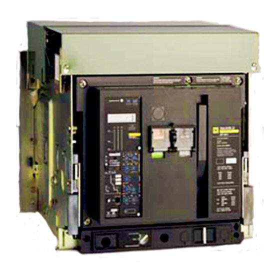
Masterpact ™ MP ci rcu it breaker
table of contents
bcsswitchgear.com | 888.599.0486
MERLIN GERIN
Switchgear | Circuit Breakers | Parts | Tech Support
universal power breaker
other perfonnances
ST 2080
for general application
ST 308S - ST 318S
for selective application
ST 408S - ST 4 1 8S
for selective application and generator protection
load monitoring, fault and alarm indicators
mini test kit, portable test kLt
closing coil
shunt trip
instantaneous undervoltage trip device
time delayed undervoltage trip device
heavy duty auxiliary switches
standard auxiliary switches
24
overcurrent trip switch
"ready to close" switch
connected position switches
disconnected position switches
test position indication
operating diagrams
disconnected position locking
safety shutters, shutters lock
accessory wiring diagrams
Need Help? 888.599.0486
page
2
2
2
2
2
2
2
5
6
6
7
8
9
1 0
1 1
1 1
1 2
1 2
1 2
1 3
13
13
1 3
1 4
1 4
1 4
1 5
1 5
1 5
1 5
1 5
1 6
1 6
1 6
1 7
1 8
1 8
1 8
1 8
1 8
1 8
1 9
20
20
20
20
21
28
30
35
36
37
38
Advertisement
Chapters
Table of Contents

Related Manuals for Merlin Gerin Masterpact MP

Summary of Contents for Merlin Gerin Masterpact MP
-
Page 1: Table Of Contents
| 888.599.0486 Need Help? 888.599.0486 MERLIN GERIN... -
Page 2: Introduction
100% rated MasterpactT M circuit breakers are designed for continuous operation at 1 00% of their current rating as permitted by the N EC. (UL listing applies up to 3000 A ) bcsswitchgear.com | 888.599.0486 Need Help? 888.599.0486 MERLIN GERIN... -
Page 3: Advantages
All accessory terminals are located on a connecting block which is accessible from the front even with the breaker in the test or disconnected position. This is particularly useful for field inspection and modification. disconnected position bcsswitchgear.com | 888.599.0486 Need Help? 888.599.0486 MERLIN GERIN... - Page 4 • • • • additional functions • • • • ground fault • • • • load monitoring • type. • • • • fault indicators not available MP 63 <D built-in ammeter MERLIN GERIN...
-
Page 5: Description
(Kirk key lock) disconnected position padlocking drawout position indicator showing that the circuit breaker is in the connected, test or disconnected position racking crank housing door escutcheon fault indicator and reset button open position locking (Kirk key lock) MERLIN GERIN... -
Page 6: Control Units
I control voltage 1 20 to 240V ± accuracy 1 ,5 %CD fault indicators local by mechanical pop-out type indicator remote by overcurrent trip switch-see page 1 5 total indudinQ current accu r acy sensors:± 4,5% <D MERLIN GERIN... -
Page 8: Ground Fault Protection
F - see page 1 0 built-in ammeter option I control voltage 1 20 to 240V 50-60H z display phase 1 , phase 2, phase 3, phase max. accuracy ± 1 ,5 % ® MERLIN GERIN... - Page 9 ST 418S with option Z and W may be also interlocked with Compact CK type molded case circuit breakers with Z SI ground fault • option. no. 18 to 14 AWG cables, twisted in pairs (approx. one turn per 4"). Max. length feet not ground. MERLIN GERIN...
-
Page 11: Built-In Ammeter 1
ST 2 08 0 - ST 308S - ST 318S 150 sec. 2 0 sec. ST 408S - ST 4 18S 4 0 sec. IN T 180 sec. 5 00 sec. MERLIN GERIN... -
Page 12: Accessories 1
: accessory terminals are of connection scewless type and may connected by standard copper wires A WG. cable strip length approximate. 3/8" MERLIN GERIN... -
Page 13: Spring Charging Motor 1
The breaker re-closedonly if closing coil is momentarily de�nergized. note: this anti-pumping function disabled by series connecting a "ready to close" switch (P F). MERLIN GERIN... - Page 14 60Hz If required, this time delay can be overridden by connecting an external switch on an 4 80 additional circuit (wired by the user). Field installable. (inrush and sealed) : consumption 20VA 20VA 15W 15W MERLIN GERIN...
-
Page 15: Additional Auxiliary Switches
• locked nor padlocked, the breaker is in the fully connected = - - - t position. This contact can series connected to the closing release (XF) to disable the anti pumping function. Field installable. MERLIN GERIN... - Page 16 • drawout. page for operating diagrams test position indication By series connection of CD and CE contacts the test position may be discriminated. current ratings (A) 0. 5 0. 2 5 MERLIN GERIN...
- Page 17 1112" -<< >>- • ronnect � secondary disconnect position • connected position switches (CE) closed • disconnected position switches (CD) note: position switches are shown with the breaker in the connected position MERLIN GERIN...
-
Page 18: Pushbutton Locking Device 1
® funct1on this anti-pumping function can be note disabled by series connecting •ready to close" switch (PF) with the closing coil (XF). same anti-pumping function with undervoltage trip device MERLIN GERIN... -
Page 19: Interlocking Rods 1
2 current transformers. )-------}-------) 1 uses power supplied by 1 group of transfonners N N2 or N3 or of generators, forbidding any connection in parallel. MERLIN GERIN... -
Page 20: Rejection Feature
Hinged-mounted and locked with a milled head, this cover is designed to be installed on the door escutcheon. It provides a higher degree of protection and is suitable for fixed or drawout mounted breakers. MERLIN GERIN... -
Page 21: Time Current Curves
.5 .6 7 B .9 1 1.2 1.5 5 6 7 B910 Jo 40 so so 300 400 «t CD,.._ multiple of current setting (lr) -- -- -- -- -- -- -- -- -- -- -- -- -. MERLIN GERIN... - Page 22 · -+ so R g g g (lr)---- -- -- --• 8 9 1 7 8 9 1 1 2 1 5 9 1 0 m ultiple-of current setting multiple o f instantaneous pickup ---- --1• •--- -- MERLIN GERIN...
- Page 23 7 .8 9 1 1 2 1 5 40 so 60 "' 0 0 000 6 7 8 9 1 0 300 400 l.() t0 f'... GO Ol 0 <t tO I'-- current setting ( l r) multiple MERLIN GERIN...
- Page 24 8 .9 1 1 2 6 7 8 9 10 .5 .6 � 9 1 0 ---- --1� multiple o f current aeHing (lr) ---- -- -- -. multiple of Instantaneous pickup •--- -- -- - •--- - MERLIN GERIN...
- Page 25 � .. 10 current sett1ng short time pickup: 1 .6 (lr) so sa f'- <Xl C'l s 0 0 0 0 0 0 300 400 6 7 .8 9 1 1 2 6 7 8 9 1 0 MERLIN GERIN...
- Page 26 Masterpact™ MP ci rcu it breaker ti me cu rrent cu rves ground fault protection ST 308ST - ST 31 8ST - ST 408ST - ST 418ST � 0: --: tO t-- CO C'l ° 6 7 .8 . 9 1 1 2 1 .
- Page 27 6 7 .8 .9 1 6 7 8 9 1 0 5 .6 .7 .8 9 1 1 .2 1 . 5 6 7 8 9 1 0 - -- multiple of current setting multiple of current setting (lr MERLIN GERIN...
- Page 28 1 1 2 2 1 2 3 1 1 1 2l �1 41 - - ?o- 1 - �l-1 2 5 1 I B 1 ..- +-- - _j_ - - -L � - - �- - --l. _ _ _ ._ _ - MERLIN GERIN...
-
Page 30: Dimensions
1 . 1 8/30 MP40 · r:15 1:75 � 6.3o 6.30 � 2.36 2.36 3.94 1 175 � 4 � � J . fL ·7 . . 78 +-L- 19 8 45, 7 74, 3 45, 7 1 14,3 4.72 - 120 MERLIN GERIN... - Page 31 (4) mounti n g hol e s . 4 4 di a 2 . 17 12. 8 2. 17 -3. 9 4 6. 8 9 3 . 3 5 ___(- 4.21 13. 8 o - 100 ' 1 75 350,5 MERLIN GERIN...
- Page 32 7 -"di s connected" posi t i o n 14.21 o § � �o (4) mounti n g hol e s . 4 4 di a 2 . 17 12.8 2. 17 ¢ 1 1 17 . 14 MERLIN GERIN...
- Page 33 · o § ��A 1 7 . 2 0 10. 2 4 (4) mounti n g hol e s . 4 4 di a I ( I O I Q 12.8 fJ 1 1 2.17 - 2.1 17.14 MERLIN GERIN...
- Page 34 "wi t hdrawn" posi t i o n 19 . 56 1 4�r-"di s connected" posi t i o n 14.21 24 3 o§��a 6 ) mounti n g hol e s . 4 4 ¢ 1 1 ---- -1 - -------- - MERLIN GERIN...
-
Page 35: Switch
M P circuit breaker, except that it is not accessories equipped with a control unit. wiring diagrams dimensions Caution : switch does not provide overcurrent protection. Switch can be protected by a MasterpactTM circuit breaker. <D ® not UL listed control un� not required MERLIN GERIN... -
Page 36: Appendix
Remove the dust and dirt that may have accumulated on the circuit breaker surface and terminals. mechanical checks For long periods circuit breakers may not be required to operate on overload or short circuit conditions. Therefore it is essential to operate the breaker periodically. MERLIN GERIN... -
Page 37: Endurances
(electricalat 480V). Endurance may be increased by simple maintenance (changing arc chutes and some visual inspections) every 1 ,000 operations, and on site by our after sales service every 3,000 electrical operations and at 1 0,000 mechanical operations. MERLIN GERIN... -
Page 38: International Standards
For further information, please contact In addition to UL 489, MasterpactT M circuit rated voltage (V) your Merlin Gerin representative. breakers comply with IEC 1 57-1 standard as UL 489 listed IEC 1 57-1 per table below:... - Page 41 Masterpact ® c i rc u it b reaker table of contents page universal power circuit breaker introduction interrupting ratings ratings tropicalization standard compliance other performances advantages description control units STR 280 for general application STR 38S for selective application STR 58U for universal application neutral protection, zone-selective interlocking fault and alarm indicators...
-
Page 42: Introduction
Masterpact ® c i rc u i t b reaker i ntrod uction i nterrupting ratings UL489/NEMA AB1 UL1 066/ANSI C37-1 3/NEMA SG3 type rating 480V 600V short type rating 480V short 600V · N� time time MC08 N1 50kA 50kA 42kA MP08 H 1... -
Page 43: Advantages
Masterpact ® c i rc u it b reaker advantages true 2-step stored energy designed for no drawout circuit breaker mechan ism maintenance ... • design The closing time is less than 5 cycles. The circuit breaker has fewer parts (by a the drawout assembly mechanism allows The circuit breaker is operated via a stored factor of at least 5) than conventional circuit... - Page 44 Masterpact ® ci rcu it b reaker advantages • improved features segregated compartment Once the front cover has been removed, giving access to the auxiliary compartment, the main contacts remain fully isolated. Furthermore, interphase partitioning allows full insulation between each pole even if the •...
-
Page 45: Description
Masterpact ® circu it breaker description description control terminal covers 2 accessories and control unit front connecting block 3 position carriage switches 4 arc chute 5 opening coils 6 spring charging motor 7 front cover 8 control unit 9 racking crank 1 0 handling handgrip 1 1 retractable rails 12 pull-out handgrip... -
Page 46: Control Units
STR 280 Masterpact ® c i rc u i t b reaker for general appl ication control u n its mechanical pop-out type fault indicator • and reset button • indicates that a fault trip has occurred prevents reclosure of the circuit breaker after fault until reset 2 ammeter (LCD digital display) •... - Page 47 Masterpact ® circ u i t b reaker STR 385 for selective appl ication contro l u n its mechanical pop-out type fault indicator • and reset button • indicates that a fault trip has occurred prevents reclosure of the circuit breaker after fault until reset 2 ammeter (LCD digital display) •...
- Page 48 STR 58U Masterpact ® c i rc u it b reaker for u niversal appl ication control u n its 1 mechanical pop-out type fault indicator • and reset button • indicates that a fault trip has occurred prevents reclosure of the circuit breaker after fault until reset 2 switch selector for the type of fault to be remotely indicated and reset flat push...
- Page 49 STR 58U Masterpact ® c i rc u it b reaker for universal application control u n its 4 to 6 rating plugs available per sensor rating: see STR 280 control unit rating plug current setting 0.8 to 1 x rating plug (pick up at 1 . 1 x current setting) long-time delay bands 0.94 - 1 .88 - 3.75 - 7.50 - 1 5 - 30s at 6 x current setting...
- Page 50 neutral sensor Masterpact ® ci rcu it b reaker zone-selective i nterlocking contro l u n its neutral sensor main circuit breaker G round-fault protection may be applied on 304W or 303W circuits. On 304W circuits an external neutral sensor must be used. This neutral current sensor must have the same ampere rating as the circuit breaker.
-
Page 51: Fault And Alarm Indicators 1
Masterpact ® circ u i t b reaker fau lt and alarm indicators control u n its fau lt indicator (option F) configuration with configuration with interruptible In addition to the mechanical fault indicator, reliable control voltage control voltage " " "... -
Page 52: Load Monitoring 1
load monitoring Masterpact ® c i rc u it b reaker m i n i test kit contro l u n its portable test kit load monitoring (option R) The option R provides two independent static contacts which operate when the •... -
Page 53: Accessories 1
secondary disconnects Masterpact ® circ u i t b reaker accessories secondary discon nects location Electrical accessories are UL Listed for field installation per UL file E1 1 3554. disconnected They are provided with terminals. They are position located on secondary disconnecting blocks •... -
Page 54: Spring-Charging Motor 1
spring charging motor Masterpact ® c i rcu it b reaker closing coil accessories The Masterpact circuit breaker i s equipped -----r- - --,--- - - - - - with a true two-step stored energy mechanism which insures fast opening and spring closing operations and complete open-close... -
Page 55: Shunt Trip 1
Masterpact ® c i rc u it breaker open ing coils accessories Three types of voltage releases can be used Release combinations • for remote opening of the circuit breakers: Each Masterpact circuit breaker can be • • shunt trip (MX) equipped with: •... -
Page 56: Standard Auxiliary Switches 1
Masterpact ® c i rc u it breaker auxil iary switches accessories - � � - - - - - - - � � heavy usage auxiliary : M-- --r:CZ switches (OF) tH-- � closed 4 SPOT switches with double break 32 34 I open - - construction. -
Page 57: Connected Position Switches 1
connected and disconnected Masterpact ® c i rcu it brea ker position switches accessories connected position switches (CE) A block of four SPOT switches operated close to the connected position. The switch block is field-installable. disconnected position switches (CD) A block of two SPOT switches operated close to the fully-disconnected position. - Page 58 operating diagrams Masterpact ® c i rcu it b reaker accessories auxiliary switches tully tully closed open closed 13/s in. main contact position o--G: between contacts (9.5 3/8 in. between contacts heavy usage (OF) in open position � standard closed .
-
Page 59: Push Button Locking Device 1
locking devices Masterpact ® circu i t b reaker summary of i nterlockings accessories p ush button locking device (VBP) This device prevents local manual operation of the circuit breaker by covering the opening and/or closing the push buttons. This locking device can be locked by a padlock or a sealing lead. -
Page 60: Interlocking Rods
interlocking rods Masterpact ® c i rc u it b reaker accessories Two or three Masterpact circuit breakers can possible mounting arrangements between be mechanically interlocked by means of three stacked circuit breakers rods or cables. This accessory is mountable on the right side of the circuit breaker. -
Page 61: Safety Shutters, Shutters Lock
safety shutters Masterpact ® c i rc u it b reaker rejection feature accessories interphase barrier transparent cover safety shutters shutters lock (VVC) Comprising two independent parts, line and A movable and lockable slide (padlock not • load side, the safety shutters automatically supplied) is used to: block access to the main disconnects when lock the line or load shutters in the closed... - Page 62 Masterpact ® switch rati ngs MP08 NA 50,000 50,000 M P 1 2 NA 1 200 50,000 1 200 50,000 50,000 M P 1 6 NA 1 600 1 600 50,000 MP20 NA 2000 50,000 2000 50,000 MP25 NA 2500 50,000 2500 50,000...
-
Page 63: Time Current Curves
Masterpact ® circ u i t b reaker t i m e cu rrent cu rves overcurrent protection STR 280 eo \2 /6 ° 0 g 8 § 8 8 88 8 § § § § § §§§ 5 6 7 8 9 1 0 40 50 5 6 7 8 9 1 1 2 1 5 1 000... - Page 64 Masterpact ® c i rc u it b reaker t i m e cu rrent cu rves overcurrent protection STR 38S so so R &l g � so so re an�� ; .6 .7 .8 .9 1 1 2 1.5 6 7 8 9 1 0 5 6 7 8 9 1 0 ����...
- Page 65 Masterpact ® c i rc u it b reaker t i m e cu rrent c u rves overcu rrent protection STR 58U 1 0000 .5 .6 .7 . 8 .9 1 1.2 1.5 2 40 so so f2 � g s 4 5 6 7 8 9 1 0 30 40 so so R: g g �...
- Page 66 Masterpact ® c i rc u i t breaker t i m e c u rrent c u rves ground-fault protection STR 38S - STR 58U § g g g g g 1'-- 0 0 0 40 50 60 ° o.n 0:0 c:o 0) 1'-- <:0 ()) .-...
- Page 67 Masterpact ® c i rc u it b reaker load mon itoring STR 58U g g g g g § ° 0 0 0 40 50 60 1 1 2 15 5 6 7 8 9 1 1 2 1 5 5 6 7 8 9 1 0 o �...
- Page 68 diagram n o . 689 889 Masterpact ® c i rc u i t breaker w i r i n g d i ag rams connected disconnected test standard heavy undervoltage shunt ready motor or trip duty trip device to close operator ,--1- -, ,--1- -, ,--- -t- -- -,...
- Page 69 diagram n o . 689 889 Masterpact ® c i rc u it b reaker w i r i n g d iag rams -�----�--------------------------------�-------- ----1-1 ¢ _ _ _ _ _ _ _ _ _ _ _ _ _ _ _ fault overload selected...
-
Page 70: Dimensions 3
door escutcheon Masterpact ® c i rc u it b reaker door interlock d i mensions rear cutout in./mm external neutral sensor door escutcheon (drawout mounting) door cutout drilling of the door � basi s : MP08 to MP30 - � - - - MC08 to MC32 14 9... - Page 71 M P08 - MP1 2 - M P1 6 Masterpact ® c i rc u it b reaker MC08 - MC1 6 d i mensions in./mm (M P only) Note: fixed mounting suitable for continuous operation at 1 00% 4 53 0.
- Page 72 M P20 - MC20 Masterpact ® c i rc u it b reaker d i mensions in ./mm (MP only) fixed mounting Note: suitable for continuous operation at 1 00% rating in a minimum cubicle space 1 7.5 (445 mm) 0.56 by 21 in.
- Page 73 M P25 - M P30 Masterpact ® c i rc u it breaker d i mensions in./mm (MP only) Note: fixed mounting suitable for continuous operation at 1 00% rating in a minimum cubicle space 26 in. (660 mm) h. by 21 in. (533 mm) w. by 1 6 in. (406 mm) d. with a ventilation of 30 sq.
- Page 74 MC32 Masterpact ® c i rc u i t breaker d i mensions in./mm drawout mounting Note: suitable for continuous operation at 1 00% rating in a minimum cubicle space 22 in. (559 mm) by 25 in. (635 mm) w. by 16 in. (406 mm) d. with a ventilation of 30 sq.
- Page 75 M P40 - M P50 Masterpact ® c i rc u i t b reaker MC40 - MC50 d i mensions in./mm (MP only) MP40 Note: suitable for continuous operation fixed mounting MP40 248 m142 at 1 00% rating in a minimum cubicle 9 .
- Page 76 M P63 Masterpact ® c i rc u it b reaker d i mensions in ./mm Refer to shop drawings for verification. drawout mounti ng withdrawn position 24 3 � 45 r- -- d " 1sconnec e pos1t1on 14.21 � cell (insulati n not required) 1 .75...
-
Page 77: Routine Maintenance Guidelines
If there is discoloration malfunction, repairs must be made at a resistance test may be performed as due to overheating, the joint should be Merlin Gerin factory or by an authorized indicated in NEMA standard publication dissassembled and the surface cleaned representative. -
Page 78: Endurances
. 500 ' 500 1 400 , 400 · 1 See tables 1 and 3. ANSI Service maintenance by a Merlin Gerin ,500 mechanical 1 1 2,500 4,000 . 4,000 ; NS 1 ,500 representative will extend the endurance... -
Page 79: International Standards
international standards Masterpact ® c i rc u it b reaker append ix molded case circuit breaker A 4-pole version complements the product line. For further information, please contact In addition to UL 489 and ANSI C37-1 3 a sales representative. Masterpact circuit breakers comply with IEC 947-2 standard as per the table below: type... -
Page 80: Thermal Memory
thermal memory Masterpact ® c i rc u it b reaker appen d i x purpose MP1 008A.O MP1 008A.O The thermal memory function allows an temp. optimization of cables or bus bar protection in case of low amplitude repetitive faults. Such faults can be due to repetitive motor starlings, fluctuating load or subsequent reclosing after a fault.
Need help?
Do you have a question about the Masterpact MP and is the answer not in the manual?
Questions and answers