Table of Contents
Advertisement
Quick Links
Advertisement
Chapters
Table of Contents

Related Manuals for Sony HDC-F950


Summary of Contents for Sony HDC-F950
- Page 1 HD COLOR VIDEO CAMERA HDC-F950 電気製品は、安全のための注意事項を守らないと、火災 や人身事故になることがあります。 このオペレーションマニュアルには、 事故を防ぐための重要な注意事項と製 品の取り扱いかたを示してあります。 このオペレーションマニュアルをよく お読みのうえ、 製品を安全にお使いください。 お読みになったあとは、 いつ でも見られるところに必ず保管してください。 OPERATION MANUAL 1st Edition (Revised 1) [Japanese/English]...
- Page 2 安全のために ソニー製品は安全に十分に配慮して設計されています。 しかし、 電気製品は まちがった使い方をすると、 火災や感電などにより死亡や大けがなど人身事 故につながることがあり、危険です。 事故を防ぐために次のことを必ずお守りください。 安全のための注意事項を守る 3(J)∼6(J)ページの注意事項をよくお読みください。 定期点検を実施する 長期間安全に使用していただくために、 定期点検を実施することをおすすめ します。 点検の内容や費用については、 ソニーのサービス担当者または営業 担当者にご相談ください。 故障したら使用を中止する ソニーのサービス担当者または営業担当者にご連絡ください。 万一、異常が起きたら 1 電源供給側の電源を切る。 • 異常な音、 2 光電気複合ケーブルや DC 電源コードを抜く。 におい、煙 3 ソニーのサービス担当者または営業担当者に修 が出たら 理を依頼する。 • 落下させた ら すぐに電源供給側の電源を切り、消火する。 炎が出たら 警告表示の意味 このオペレーションマニュアル および製品では、次のような表...
-
Page 3: Table Of Contents
目次 第1章 概要 第2章 各部の名称と働き 第3章 準備 第4章 記録のための調整と設定 警告 ... 注意 ... 電池についての安全上のご注意 ... 特長 ... システム構成 ... アクセサリー取り付け部 ... コントロール部 ... 使用上のご注意 ... 接続と電源 ... 3-2-1 接続 ... 3-2(J) 3-2-2 電源の供給 ... 3-3(J) レンズの取り付け ... フランジバックの調整 ... ビューファインダーの位置調整 ... 三脚への取り付け ... ショルダーベルトの取り付け... - Page 4 目次 第4章 記録のための調整と設定 (続き) 第5章 撮影 付録 2(J) 目 次 4-6-8 その他の設定 ... 4-21(J) 4-6-9 オペレーターフ ァイ ルを操作する ... 4-22(J) 4-6-10 レンズフ ァイ ルを表示する ... 4-22(J) PAINT メニュー ... 撮影操作 ... 仕様 ... 撮影前の点検 ... 用語解説 ... 4-23(J) 5-1(J) A-1(J) A-3(J) A-4(J)
- Page 5 下記の注意を守らないと、 火災 感電 死亡 大けが や により や につながることがあります。 光電気複合ケーブルや 電源コードを傷つけない 光電気複合ケーブルやDC電源コードを傷つけると、 火災や感電の原因とな ります。 ・ ケーブルを加工したり、傷つけたりしない。 ・ 重いものをのせたり、引っ張ったりしない。 ・ 熱器具に近づけたり、加熱したりしない。 ・ ケーブルを抜くときは、必ずプラグを持って抜く。 万一、ケーブルが傷んだら、ソニーのサービス担当者に交換をご依頼くだ さい。 3(J)
- Page 6 下記の注意を守らないと、 けが をしたり周辺の物品に 4(J) 損害 を与えることがあります。 分解しない、改造しない 分解したり、改造したりすると、感電の原因となります。 内部に水や異物を入れない 水や異物が入ると火災や感電の原因となります。 万一、 水や異物が入ったときは、 すぐに電源供給側の電源を切り、 光電気複 合ケーブルや接続コードを抜いて、 ソニーのサービス担当者または営業担当 者にご相談ください。 油煙、湯気、湿気、ほこりの多い場所では設置 上記のような場所で設置・使用すると、火災や感電の原因となります。 指定された (カメラコントロールユニット)を使用する 指定以外の CCU を使用すると、火災や感電の原因となります。 側板をあけるときは、高温部分に触れない 機器を使用中または使用直後に側板を開けると、 電源部が高温になっている ため、やけどすることがあります。側板を開けて点検や調整を行うときは、 電源を切ってから少なくとも 10 分間放置してください。 回転式マルチコネクターは慎重に扱う 回転式マルチコネクターを乱暴に扱うと、 コネクター部が回転して指を挟む ことがあります。 ケーブルの接続および取り外しは無理な力をかけずに慎重 に行ってください。 使用中、放熱口をふさがない 内部温度が上昇して、筐体でやけどするおそれがあります。 • 使用しない...
- Page 7 機器や部品の取り付けは正しく行う 別売りの機器や部品の取り付け方法を誤ると、 機器が落下して怪我をするこ とがあります。 下記の機器や部品を取り付けるときは、 マニュアルをよく読 んだうえ、確実に取り付けてください。 • レンズ •ショルダーベルト •三脚アタッチメント • バッテリー 5(J)
-
Page 8: 電池についての安全上のご注意
電池についての安全上のご注意 6(J) こ こでは、 本機での使用が可能なリ チウムイ オン電池およびバッ クアップ用マンガン リチウ ム電池についての注意事項を記載しています。 万一、異常が起きたら • 煙が出たら 1 機器の電源スイ ッチを切るか、バッテリ ーチャージャーの電源プラグを抜く 。 2 ソニーのサービス担当者に連絡する。 • 電池の液が目に入ったら すぐきれいな水で洗い、ただちに医師の治療を受ける。 • 電池の液が皮膚や衣服に付いたら すぐにきれいな水で洗い流す。 • バッテリー収納部内で液が漏れたら よ く ふき取ってから、新しい電池を入れる。 下記の注意事項を守らないと、破裂・発火・発熱・液漏れにより、 死亡や大けがになることがあります。 • 充電には、 ソニーの専用バッテ リ ーチャージャーを使用する。 充電のしかたについては、バッテ リ ーチャージャーの取扱説明書をよく お読みく ださい。 •... -
Page 9: 特長
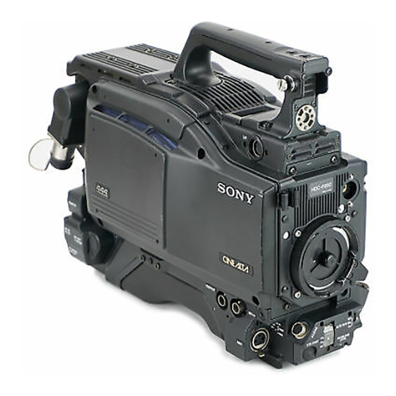
特長 HDC-F950は、 HD-SDI 4:4:4 (RGB)出力を有するポータブルカ ラービデオカメ ラです。 HDカメ ラコン ト ロールユニッ トHDCU-F950やVTRと接続する こ と によ り 、主に映画制作用カメ ラ と して機能します。 高画質・高性能 新開発の 220 万画素、 型 1080 Phase II FIT-CCDと、独自の CCD出力信号プロセス回路および12ビッ トA/Dコンバーターの採 用によ り 、高画質・高性能を実現しま した。 また、 HD-SDI 4:4:4 (Dual Link)対応によ り、 さ らに高画質での出... - Page 10 の状態を容易に確認する こ とができます。 光デジタル伝送 光電気複合ケーブルを用い、カメ ラ-カメ ラコン ト ロールユニッ ト間 で 3 ギガビッ ト デジタル光伝送を行います。 高解像度 型液晶マルチフォーマットカラー ビューファインダー HDC-F950の開発に伴い、 新たにマルチフォーマッ ト対応の3型液 晶カラービューフ ァイ ンダーHDVF-C30Wを用意しま した。 感電防止機能 接続が不完全なと き、 HDCU (カメ ラコ ン ト ロールユニッ ト) からの高 電圧供給が停止します。 ゼブラパターン ビューフ ァイ ンダー画面上に現れる映像レベルが約70%および100%以...
-
Page 11: システム構成
システム構成 本機の関連機器およびアクセサリ ーを下図に示します。 エレクトロニック ビューファインダー HDVF-C750W ビューファインダー HDVF-20A ビューファインダー BKW-401 回転機構 ズームレンズ カラービデオカメラ HDC-F950 HD CCD ブロックアダプター 三脚アタッチメント VCT-14 リターンビデオ エレクトロニック セレクター CAC-6 エレクトロニック ビューファインダー HDVF-C30W バッテリーアダプター BKP-L551 光ファイバーケーブル FC2-PD50/PD250 CCA-5 ケーブル HKC-T950 バッテリーパック BP-L60/L80 カメラ コントロールユニット HDCU-F950 リモート コントロール... -
Page 13: アクセサリー取り付け部
アクセサリー取り付け部 ショルダーパッド 1 ショルダーベルト取り付け金具 シ ョルダーベル トの一端をこの取り付け金具に取り付け、 も う一端を 右側面のシ ョルダーベル ト取り付け金具 (2-8(J)ページ参照) に取 り付けます。 2 ビューファインダー前後位置固定レバーとロックつまみ ビューフ ァイ ンダーの位置を前後方向に調整する とき、 このレバー とつまみをゆるめます。 3 ビューファインダー左右位置固定リング ビューフ ァイ ンダーの位置を左右方向に調整する と き、 このリ ングを ゆるめます。 4 レンズ用ケーブルクランプ レンズのケーブルを固定します。 5 レンズ固定レバー レンズ(別売り)をレンズマウン ト に固定します。 取っ手... -
Page 14: コントロール部
コントロール部 コントロール部 前部(右) INCOM ボタン RET 1 ボタン Y/RGB スイッチ R/G/B スイッチ ASSIGNABLE スイッチ FILTER つまみ AUTO W/B BAL スイッチ INCOM (インターカム )ボタン 押している間、 イ ンターカム1 のマイ クが ONになり ます。 RET 1 (リターンビデオ )ボタン 押している間、 カメ ラコン ト ロールユニッ ト からのリ ターンビデオ1信 号をビューフ... - Page 15 AUTO W/B BAL (ホワイトバランス 自動調整)スイッチ ホワイ トバラ ンス とブラ ックバラ ンスを自動調整します。 :ホワイ トバラ ンスを自動調整する。 :ブラ ッ クバラ ンスを自動調整する。 CAMERA/VTR スイッチ 本機と接続したVTRへのコン ト ロール信号を切り換えます。 設定に よ り 、 VTRによる記録開始の機能が次のよ う に変わり ます。 CAMERA 機能 SAVE カメ ラの電源 OFF。 SAVE カメ ラの電源 ON。 VTR STARTボタ ンを押すと、 数秒後に記録が始まる。...
- Page 16 コントロール部 前部(左) TEST OUT 端子 現在は使用しません MIC 1 IN 端子 RET 1 ボタン MIC IN スイッチ TEST OUT (テスト出力)端子 ( 必要に応じてモニターに接続します。 Y/RGBスイ ッチとR/G/Bスイ ッチで選択した信号を出力します。 MIC 1 IN (マイク 入力) 端子( マイ クを接続します。 MIC INスイ ッチによって、後面の AUDIO IN CH-1 端子と切り換 えます。 RET 1 (リターンビデオ...
- Page 17 SHUTTER (シャッター) スイッチ OFF: 電子シャ ッ ターは働かない。 電子シャ ッ ターを使用する。 SEL: スイ ッチをこの位置にすると、シャ ッタースピー ドおよび シャ ッ ターモー ドの設定が切り換わる。 ◆詳しく は「4-2 電子シャ ッ ターの設定」 (4-4(J)ページ)をご覧く ださい。 INCOM/EAR LEVEL (インターカム まみ イ ンカムおよびイ ヤホンの音声レベルを調整します。 イ ンカムレベルの調整は後面(右)パネルの INCOM LEVELス イ ッチが F 側に設定されている と きに有効です。 VTR START (記録開始...
- Page 18 コントロール部 後面(左) 1 タリーランプとタリースイッチ 端子 INCOM1 、 端子 EARPHONE ジャック TRACKER 端子 GENLOCK IN/RET IN/ PROMPTER OUT 端子と 切り換えスイッチ AUDIO IN 1 、 端子 スイッチ 1 タリーランプとタリースイッチ :外部からのタ リ ーボタ ンやCALLボタ ンなどによる呼び出し 時にタ リ ーラ ンプが点灯する。 : タ リ ーラ ンプを点灯禁止にする。 (カメラコントロールユニット)端子...
- Page 19 AUDIO IN (オーディオ入力)1、 ン) スイッチ オーディ オ信号を入力します。 チャ ンネル1、 2それぞれに対して入 力選択スイ ッチ、マイ ク電源スイ ッチが用意されています。 入力選択スイッチ マイク電源スイッチ LINE MIC OFF+48V LINE MIC OFF+48V AUDIO CH-1 CH-1 入力選択スイッチ :入力する外部音声信号を選択します。 LINE :ライ ン入力を接続する と き。 :マイクを接続するとき (マイ クのゲイ ン設定は、メ ニューで行います) 。 マイク電源スイッチ :マイ クを接続したと き、 マイ クに電源を供 給するかどうかを設定します。...
- Page 20 コントロール部 後面(右) 1 メモリースティック部 POWER スイッチ 1 メモリースティック部 蓋の中に、 メモリ ースティ ッ クを挿入するスロ ッ ト と、 取り出すと きに 押すイ ジェク ト ボタ ンがあ り ます。 スロ ッ ト に挿入したメモリ ースティ ッ クにデータ を書き込んだり 、 メモ リ ースティ ッ クからデータを読み出している ときはイ ジェク ト ボタ ンが 赤く...
- Page 21 INCOM1 側 調 整 つ ま み スイッチ PROD ライン選択スイッチ INCOM LEVEL TALK LEVEL/TALK スイッチ INCOM INCOM 調整つまみ (プログラム) 調整つまみ スイ ッチ:プログラム音声の受 信レベルを調整します。 それぞれ対応するスイ ッチで、 プログ ラム1 か 2を選択できます。 ライン選択スイッチ :イ ンターカムライ ンを選択します。 PROD :プロデューサーライ ンを使用する と き。 :エンジニアライ ンを使用する と き。 LEVEL/TALK (レベル...
-
Page 23: 使用上のご注意
使用上のご注意 強い衝撃を与えない 内部構造や外観の変形などの損傷を受ける こ とがあ り ます。 使い終わったら 電源スイ ッチを切ってく ださい。 使用、保管場所 水平な場所、空調のある場所に保管してく ださい。 次のよう な場所での使用および保管は避けてく ださい。 • 極端に暑い所や寒い所 • 湿気の多い所 • 激しく 振動する所 • 強い磁気を発生する所 • 直射日光が長時間あたる所や暖房器具の近く 3-1(J) 第 章 準備... -
Page 24: 接続と電源
接続と電源 3-2-1 接続 本機には、 VTR、カメ ラコン ト ロールユニッ ト 、 またはリモー ト コン ト ロールパネルを接続する こ とができます。 の接続 本機に取り付けたカメ ラアダプターに、 下図のよ う にVTRを接続す る こ とができます。 HDC-F950 HD SERIAL LINK A / LINK B OUT ケーブル 4:4:4 カメラアダプターとカメラコントロールユニッ ト リモートコントロールパネルの接続... -
Page 25: 電源の供給
ユニット HDCU-F950 光マルチ コネクター DC IN カラービデオカメラ 端子 HDC-F950 • • バッテリーアダプ POWERスイ ッチをCCUに設定する と、カメ ラコン ト ロールユニッ ト が接続されている と きに電源が入り ます。 また、 EXTに設定する と、 DC IN 端子から給電されている と きに電源が入り ます。 バッテリーパックを使う バッテ リ ーパッ ク を使って電源を供給する場合は、 POWERスイ ッチ... -
Page 26: レンズの取り付け
レンズの取り付け 本機に取り付ける手順は、次のとおりです。 レンズ固定レバーを押し上げて、 レンズマウン ト から レンズマウ ン ト キャ ップを外す。 レンズマウ ン ト 上部中央の凹部にレンズの位置決めピンを合わ せ、 レンズをマウン ト に差し込む。 レンズを支えながら、 レンズ固定レバーを押し下げてレンズを 固定する。 3-4(J) 第 章 準備 ◆ レンズの取り扱いについては、 レンズに付属の取扱説明書をご覧く ださ い。 レンズケーブルをLENS 端子に接続する。 レンズケーブルをケーブルク ラ ンプに押し込む。... -
Page 27: フランジバックの調整
フランジバックの調整 次のよう な場合、 フラ ンジバック の調整が必要です。 • レンズを初めて取り付けたと き • レンズを交換したと き • ズーム操作の際に、望遠・広角の両方で焦点がきちんと合わな いとき フラ ンジバッ クの調整の手順は、次のとおりです。 絞りのモー ドを手動にして、絞り を開放にする。 フランジバック調整用チャー ト を本機から3mぐらいの所に置 き、適正な映像出力レベルが得られるよう に、照明を調整す る。 リ ング固定ネジをゆるめる。 手動または電動で、ズーム リ ングを望遠位置にする。 フラ ンジバッ ク調整用チャー ト を写し、 フ ォーカス リ ングを回して 焦点を合わせる。... -
Page 28: ビューファインダーの位置調整
ビューファインダーの位置調整 ビューフ ァイ ンダーの位置を左右方向および前後方向に調整して、 ビューフ ァイ ンダー内を見やすく する こ とができます。 左右方向の調整 ビューフ ァイ ンダー左右位置固定リ ングをゆるめる。 ビューフ ァイ ンダーを左右にス ライ ド させ、 内部が見やすい位置 に調整する。 ビューフ ァイ ンダー左右位置固定リ ングを締める。 3-6(J) 第 章 準備 本機をキャリングケースに収納するときは ビューフ ァイ ンダーをマイ ク側いっぱいに寄せ、 ビューフ ァイ ンダー 左右位置固定リ ングを締めた状態で収納します。 前後方向の調整... - Page 29 ビューファインダーが脚に当たらないようにする には 本機を持ち運ぶと きに、 ビューフ ァイ ンダーが脚に当たらないよ う に するには、 ビューフ ァイ ンダー回転機構BKW-401(別売り)を取り付 けて、 ビューフ ァイ ンダーを上部に回転させておきます。 ご注意 ビューフ ァイ ンダーを上部に回転させる前に、 ビューフ ァイ ンダーを 少し前に引き出した位置で固定してく ださい。 ビューフ ァイ ンダーの 前後方向の位置が最後部になっている と、 ビューフ ァイ ンダー回転 機構のアームが本機の取っ手に当たり ます。 3-7(J) 第 章 準備...
-
Page 30: 三脚への取り付け
三脚への取り付け 別売りの三脚アタ ッチメ ン ト VCT-14を使って本機を三脚に取り付け るには、次のよう にします。 三脚アタ ッチメ ン ト を三脚に取り付ける。 三脚アタ ッチメ ン トの底部にある穴のう ち、 本機と三脚アタ ッチ メ ン トの重心を考慮して、 適切な位置の穴を選びます。 選んだ 穴の径が、 雲台のカメ ラ取り付けネジの径と合う こ とを確認し ます。 本機を三脚アタ ッチメ ン ト に取り付ける。 アタ ッチメ ン トの溝に沿って、 カチッ と音がするまで、 本機を前 方にすべらせます。... -
Page 31: ショルダーベルトの取り付け
ショルダーベルトの取り付け 本機を肩から下げて使用する場合は、 別売りのシ ョルダーベル ト を シ ョルダーベル ト取り付け金具に取り付けます。 取り付けるには クリップ ベルトを上に引っ張って きちんと固定する。 ショルダーベルト 取り付け金具 取り外すには ここを押しながら 矢印の方向に引く。 3-9(J) 第 章 準備... -
Page 33: ブラックバランス / ホワイトバランスの調整
ブラックバランス 本機を使用し、 常に高画質の映像を得るためには、 状況に応じた ブラ ッ クバラ ンス とホワイ トバラ ンスの調整が必要です。 ブラックバランスの調整 次のよ う な場合に調整が必要です。 • 本機を初めて使用するとき • 長時間使用しなかった後に使用するとき • 周囲の温度が大幅に変化した状況で使用するとき • 設定メニューでゲイン切り換え値を変更したとき 通常は、 電源を再び入れた場合でも調整し直す必要はありませ ん。 ホワイトバランスの調整 照明条件が変わったと きには、 必ず調整し直してく ださい。 ビューファインダー画面の表示について ブラ ックバラ ンス とホワイ トバラ ンスの調整を始める と、 ビューフ ァイ ンダー画面に、... -
Page 34: ホワイトバランスを調整する
ブラックバランス ホワイトバランスの調整 ご注意 • ブラックバランス調整中、 絞りは自動的に遮光状態になりま す。 • ブラックバランス調整中、 ゲイン切り換え回路が自動的に切り 換わり、 また、 ビューファインダー画面上にフリ ッカーが数回現 れますが、 故障ではありません。 ブラックバランスの自動調整ができないとき ブラ ックバランスの調整が正常に終了しなかったときは、 ビュー フ ァイ ンダー画面に約3秒間エラーメ ッセージ 「ABB:NG」 が表示さ れます。 エラーメ ッセージが表示されたら、 再度ブラ ックバランスの調整を 試みてく ださい。 繰り返し調整を試みてもエラーメ ッセージが表示されるときは、 内 部点検をする必要があ り ます。 ◆ 内部点検については、 イ ンス ト レーシ ョ ン&メ ンテナンスマニュアルをご 覧く... - Page 35 AUTO W/B BALスイ ッチをWHT側に押して、 指を離す。 AUTO W/B BAL スイッチ スイ ッチは中央に戻り、 ホワイ トバランスの自動調整が実行さ れます。 調整中、 ビューファイ ンダー画面の左下に 「AWB:OP」 のメ ッ セージが表示されます。 約1秒で、 図のようなメ ッセージが表示され、 調整が完了しま す。 調整値は、 手順 で選択したメモリ ー(AまたはB)に自動 的に記憶されます。 AWB:OK ご注意 自動絞り機能付きズームレンズを使用した場合、 絞りがハンチン グ を起こすこ とがあ り ます。 レンズに付いている絞りのゲイ ンつま み(IG、...
-
Page 36: 電子シャッターの設定
電子シャッターの設定 こ こでは、 本機の電子シャ ッ ターで使用できるシャ ッ ターモー ドに ついて説明し、 シャ ッ ターモー ドとシャ ッ タース ピー ドの設定手順を 示します。 4-2-1 シャッターモードについて 本機の電子シャ ッ ターで使用できるシャ ッ ターモー ドと、 選択でき るシャ ッ タース ピー ドは次のとおりです。 設定できるシャッターモードとシャッタースピード シャッター シャッタースピード モード 標準 1/32、1/48、1/96、 動きの早い被写体を鮮明に 1/125、1/250、1/500、... - Page 37 モードを選択したときは 本機前面のMENU SELつまみ/ENTERボタ ンを回転させてス ピー ドを変更する こ とができます。 1度選択したシャ ッ タース ピー ドは、 本機の電源を切った状態でも 保持されます。 4-5(J) 第 章 記録のための調整と設定...
-
Page 38: ビューファインダー画面上の設定メニュー表示
ビューファインダー画面上の設定メニュー表示 DISPLAYスイ ッチをMENUに設定する と、 ビューフ ァイ ンダー画面 上にOPERATIONメニューが表示されます。 OPERATIONメニューはページ単位で表示されます。 OPERATIONメニューは、 各種設定値の選択や、 ビューフ ァイ ン ダー画面上に表示させる項目とその表示方法の選択に使用しま す。 メニューについて メニュー項目の全体構成を示す画面と してTOPメニュー画面が あ り ます。 メニュー画面 < TOP MENU > c USERS USER MENU CUSTOMIZE OPERATION PAINT MAINTENANCE FILE DIAGNOSIS ご注意 内部SG基板のスイ ッチ設定により、 TOPメニューの内容は異なり ます。... -
Page 39: 設定メニューの基本操作
DIAGNOSIS メニュー 自己診断情報を表示します。 メニューに戻るには 次の2とおりの方法があ り ます。 • メニュー画面の各ページの右上に表示されているTOPに→ マークを合わせ、 MENU SELつまみ/ENTERボタンを押す。 • STATUS/CANCELスイ ッチをCANCEL側に2度押す。 TOPメニュー画面に戻り ます。 ◆ これらのメニューについて詳しく は、 イ ンス ト レーシ ョ ン&メ ンテナンスマ ニュアルおよびシステムマニュアルをご覧く ださい。 4-3-1 設定メニューの基本操作 DISPLAY スイッチ STATUS/CANCEL MENU SEL つまみ DISPLAYスイ ッチをOFFからMENUに切り換える。 OPERATIONメニュー画面が表示されます。 ページ番号... - Page 40 ビューファインダー画面上の設定メニュー表示 他のページに移るには ページ番号に→マークを合わせ、 MENU SELつまみ/ ENTERボタ ンを押す。 または→マークがページ番号以外の場所にある場合は、 STATUS/CANCELスイ ッチをCANCEL側に倒す。 ページ変更モー ドになり ます。 希望のページが表示されるまでMENU SELつまみ/ENTER ボタ ンを回す。 選択したページの各項目の設定内容が表示され、 現在の選 択項目に→マークが付きます。 メニュー操作をやめるには DISPLAYスイ ッチをOFFにします。 4-8(J) 第 章 記録のための調整と設定...
-
Page 41: ビューファインダー画面上の状態表示
ビューファインダー画面上の状態表示 ビューフ ァイ ンダー画面には、 映像の他に本機の設定や動作の状 態を示す文字やメ ッセージ、 センターマーカー、 セーフティ ゾーン マーカーなどが表示されます。 DISPLAYスイ ッチがONに設定されている と き、 画面の上端、 下端 には、 OPERATIONメニューのVF DISPLAYページや関連するス イ ッチでONに設定された項目が表示されます。 また、 設定変更時 や調整経過中または調整後に、 設定内容や調整経過/結果を知 らせるメ ッセージを約3秒間表示させる こ とができます。 4-4-1 ビューファインダー画面上の状態表示の構成 表示できるすべての項目は、 下の図のよう に配置されています。 2 レンズエクステンダー D5600K モード 4 フィルター 5 ホワイトバランスメモリー... - Page 42 ビューファインダー画面上の状態表示 8 バッテリー電圧 バッテ リ ー電圧を表示します。 値 レンズのF値(絞り値)を表示します。 0 テープ残量 VTRのテープ残量(分)を示します。 残量が5分以下のときは 「5- 0」 、 5∼10分のときは 「10-5」 、 10∼15分のときは 「15-10」 、 15分以上 のときは 「F-15」 と表示します。 VTRが接続されていない場合、 表示されません。 /EVS qa シャッター シャッター/EVSの状態を表示します。 ただし、 シャッターおよび EVS共にOFFの場合、 表示されません。 4-10(J) 第 章 記録のための調整と設定...
-
Page 43: User メニューの使いかた
4-5 USER メニューの使いかた USERメニューには、 OPERATION、 PAINT、 MAINTENANCE、 FILE、 DIAGNOSISのメニューページから任意のページを選択 し、 そのページをコピーして設定することができます。 使用頻度の 高いメニューページをあらかじめUSERメニューに設定しておく と、 簡単に必要なページを呼び出して使用する こ とができます。 さ らに、 メニューの設定項目を1項目ごとに選択して設定できる USER PAGEが1から5ページまで用意されています。 USER PAGEには、 1ページに最大10のメニュー項目を設定する こ とができます。 4-5-1 USER メニューに任意のメニュー ページを設定するには TOP MENUを表示する。 ◆ 表示の方法については、 「 TOP MENU画面を表示させるには」 (4-6(J)ページ) をご覧く ださい。 MENU SELつまみ/ENTERボタ... -
Page 44: Userメニューに任意のメニューページを設定するには
4-5 USER メニューの使いかた 設定したページを並び換えるには TOP MENUを表示する。 MENU SELつまみ/ENTERボタ ンを回してUSER MENU CUSTOMIZEを選択し、 MENU SELつまみ/ENTERボタ ン を押す。 PAGE EDIT画面が表示されます。 MENU SELつまみ/ENTERボタ ンを回して移動したいメ ニューページを選択し、 MENU SELつまみ/ENTERボタ ンを 押す。 操作選択画面が表示されます。 MENU SELつまみ/ENTERボタ ンを回してMOVEを選択 し、 MENU SELつまみ/ENTERボタ ンを押す。 PAGE EDIT画面に戻り ます。 MENU SELつまみ/ENTERボタ ンを回して、 手順3で選択し たメニューページを移動したい位置に→マークを動かし、... - Page 45 MENU SELつまみ/ENTERボタ ンを回して→マークを 1 行目 に移動し、 MENU SELつまみ/ENTERボタ ンを押す。 ITEM SELECT画面が表示されます。 設定したい項目を次の手順で選択する。 ∼ から選択するときは 1 MENU SELつまみ/ENTERボタ ンを回して設定したい項 目を選択し、 MENU SELつまみ/ENTERボタ ンを押す。 操作選択画面が表示されます。 2 MENU SELつまみ/ENTERボタ ンを回してSELECTを選 択し、 MENU SELつまみ/ENTERボタ ンを押す。 USER P1 EDIT 画面に戻り、 選択した項目が表示されま す。 以降を選択するときは 1 MENU SELつまみ/ENTERボタ ンを回して画面先頭行 の数字に→マークを移動し、...
-
Page 46: Userメニューを表示するには
4-5 USER メニューの使いかた 4-5-3 USER メニューを表示するには 上記の手順で設定したUSERメニューを表示し、 他のメニューと 同じよ う に操作するこ とができます。 TOP MENUを表示する。 ◆ 表示の方法については、 「 TOP MENU画面を表示させるには」 (4-6(J)ページ) をご覧く ださい。 MENU SELつまみ/ENTERボタ ンを回してUSERを選択し、 MENU SELつまみ/ENTERボタ ンを押す。 PAGE EDIT画面の項目番号 1 に設定したメニューページが 表示されます。 他のメニューページを表示するには MENU SELつまみ/ENTERボタ ンを回して画面先頭行の数 字に→マークを移動し、 MENU SELつまみ/ENTERボタ ンを 押す。... - Page 47 OPERATION 本機では、 調整やセッ トアップ(初期設定)にOPERATION(オペ レーシ ョ ン)メニューを使います。 OPERATION 調整 セットアップ項目 ビューファインダー画面の表示の選択 ‘ ! ’ 表示の設定 1 ‘ ! ’ 表示の設定 2 マーカーの設定 ゲイン切り換えスイッチの設定 ビューファインダーの設定 オートアイリスの設定 電源設定の表示 その他の設定 オペレーターファイルの設定 レンズファイルの表示 a)これらのページは情報の表示のみで、 設定は行いません。 ◆ 上記以外の調整/セットアップの操作については、 「 4-7 PAINTメ ニュー」 (4-23(J)ページ)およびインストレーション&メンテナンス マニュアルをご覧ください。 メニューによるセットアップ OPERATIONメニューで調整およびセッ...
-
Page 48: Operation メニューによるセットアップ
OPERATION メニューによるセットアップ 4-6-1 表示項目を選択する ビ ュ ー ファイン ダ ー 画 面 に 表 示 さ せ る 項 目 の 選 択 は 、 OPERATIONメニューのVF DISPLAYページで、 項目別に表示 のON/OFFを切り換える こ とによって行います。 以下の手順でビューフ ァイ ンダー画面に表示させる項目を選択し ます。 DISPLAY スイッチ MENU SEL つまみ... -
Page 49: 表示を点灯させる項目を選択する
4-6-2 ‘ ! ’ 表示を点灯させる項目を選択 する ビューファイ ンダー画面に ‘!’ 表示を点灯させる項目の選択は OPERATIONメニューの ‘ ! ’ IND 1ページおよび ‘ ! ’ IND 2ページ で行います。 これらのページの内容は、 DISPLAYスイ ッチがONま たはOFFのと きに、 STATUS/CANCELスイ ッチをSTATUS側に倒 すこ とで確認する こ とができます。 以下の手順で ‘ ! ’ 表示を点灯させる項目を選択します。 DISPLAYスイ ッチをMENUにする。 MENU SELつまみ/ENTERボタ... -
Page 50: マーカー表示を設定する
OPERATION メニューによるセットアップ WHITE ホワイ トバラ ンスの調整方法 (P(PRST)、 A、 Bから複数 指定可) D5600K ONかOFF GAIN ゲイ ンスイ ッチの位置L、 M、 Hのいずれか SHUTT ONかOFF AUTO1、 AUTO2、 MIN、 MAXのいずれか ONかOFF FORMAT ビデオフォーマッ ト59.94I、 60I、 30PsF、 29.97PsF、 50I、 25PsF、 24PsF、 23.98PsFのいずれか IND 2 ‘!’ ページ 項目... -
Page 51: ゲイン切り換え値を設定する
続けて他の項目を設定する ときは、 手順3を繰り返す。 メニュー操作を終了する と きは、 DISPLAYスイ ッチをONにす る。 ビューファイ ンダー画面からメニュー表示が消え、 ビューファイ ン ダー画面の上端、 下端に本機の現在の状態を示す表示が現れま す。 4-6-4 ゲイン切り換え値を設定する 映像アンプのゲイ ン値を切り換えるGAINスイ ッチの設定位置L、 M、 Hに対応するゲイ ン値は、 あ らかじめOPERATIONメニューの GAIN SWページで設定しておきます。 以下の手順でゲイ ン切り換え値を設定します。 DISPLAYスイ ッチをMENUにする。 MENU SELつまみ/ENTERボタ ンを回してGAIN SWページ を表示させて、 MENU SELつまみ/ENTERボタ ンを押す。 GAIN SW ページ... -
Page 52: オートアイリスを設定する
OPERATION メニューによるセットアップ ZEBRA2 ゼブラ(100%)表示のレベル調整(88∼112%) VF DTL VFディ テール (ビューフ ァイ ンダー内のシャープネス) 調 整機能のON/OFFと レベル調整 a) ビューファインダー内のシャープネス調整は、 記録画には影響し ません。 MENU SELつまみ/ENTERボタ ンを回して→マークを設定 したい項目に合わせて、 MENU SELつまみ/ENTERボタ ン を押す。 →マークが?マークに変わり ます。 MENU SELつまみ/ENTERボタ ンを回して希望の設定に切 り換え、 MENU SELつまみ/ENTERボタ ンを押す。 ?マークが→マークに戻り、 設定値が確定します。 続けて他の項目を設定する ときは、 手順3、 4を繰り返す。 メニュー操作を終了する... -
Page 53: 電源設定を表示する
4-6-7 電源設定を表示する OPERATIONメニューのBATT ALARMページには、 電源に関す る設定状態が表示されます。 このページでは設定は行いません。 DISPLAYスイ ッチをMENUにする。 MENU SELつまみ/ENTERボタ ンを回してBATT ALARM ページを表示させて、 MENU SELつまみ/ENTERボタ ンを押 す。 BATT ALARM ページ <BATT ALARM> BATT TYPE:c AC ADP BEFORE END: --- : --- 各項目の右側に現在の状態が表示されます。 項目 表示内容 TYPE 入力電源 BEFORE END 入力電源がAC ADP以外のとき、 MAINTENANCE メニューで設定したALARM電圧を表示... -
Page 54: オペレーターファイルを操作する
OPERATION メニューによるセットアップ VTR S/S スイッチの設定 設定 機能 RET2 SW リ ターンビデオ信号2の映像をビューフ ァイ ンダーに表 示させるON/OFFスイ ッチと しての機能を割り当てる。 INCOM1 イ ンターカムマイ ク1のON/OFFスイ ッチと しての機能 を割り当てる。 INCOM2 イ ンターカムマイ ク2のON/OFFスイ ッチと しての機能 を割り当てる。 VTR S/S VTR S/S ( スター ト/ス ト ップ) スイ ッチと しての機能を 割り当てる。... -
Page 55: Paint メニュー
PAINT メニュー PAINTメニューには、ホワイトなどペイント調整項目がまと められています。 撮影シーンに合わせてペインティングしたデータ(シーン ファイル)を5通りまで保存することもできます(SCENE FILE ページ)。 ◆ 設定方法については、「4-3-1 設定メニューの基本操作」(4-7(J) ページ)をご覧ください。 PAINT メニュー画面を表示するには MENU SELつ ま み /ENTERボ タ ン を 押 し な が ら 、 DISPLAYスイッチをOFFからMENUに切り換える。 TOPメニュー画面が表示されます。 < TOP MENU > c USERS USER MENU CUSTOMIZE OPERATION PAINT MAINTENANCE FILE... - Page 56 PAINT メニュー PAINT メニュー一覧 ページ 設定項目 SW STATUS FLARE GAMMA BLK GAM KNEE WHT CLIP DETAIL LVL DEP SKIN DTL MATRIX VIDEO LEVEL WHITE R,G,B BLACK R,G,B,M FLARE R,G,B GAMMA R,G,B,M V MOD R,G,B,M FLARE V MOD TEST GAMMA LEVEL COARSE TABLE...
- Page 57 ページ 設定項目 LOW KEY SAT LEVEL KNEE POINT R,G,B,M SLOPE R,G,B,M WHT CLP R,G,B,M KNEE SAT LEVEL KNEE KNEE SAT WHT CLIP TEST DETAIL 1 LEVEL LIMITER M/WHT/BLK −99∼0∼99 CRISPEN HV RATIO FREQ DETAIL LVL DEP DETAIL2 KNEE APERTURE SKIN DETAIL SKIN DTL SKIN GATE CH SW...
- Page 58 PAINT メニュー ページ 設定項目 USER MATRIX R−G, R−B G−R, G−B B−R, B−G MATRIX PRESET USER MATRIX MULTI MATRIX MULTI MATRIX PHASE ALL CLEAR AUTO DET MATRIX PRESET USER MATRIX MULTI MATRIX a) MATRIXがOFFに設定されている場合は設定できません。 4-26(J) 第 章 記録のための調整と設定 設定 内容 −99∼0∼99 R−G, R−Bのユーザーマトリックスを任意に設定...
- Page 59 ページ 項目 SHUTTER SHUTTER/ECS ECS FREQ S-EVS SCENE FILE STORE STANDARD READ(MS→CAM) WRITE (CAM→MS) GP 1∼20 FILE ID CAM CODE DATE a) 60Iまたは59.94Iフォーマッ ト が選択されている場合のシャ ッ タースピー ド およびECS周波数です。 以下は各フ ォーマッ トのシャ ッ タース ピー ドおよびECS周波数です。 シャ ッ タースピー ド 秒 60I(59.94I): 1/100、...
-
Page 61: 撮影操作
撮影操作 撮影に際し本機の機能を十分に生かせるよ う に、 事前の点検によ り、本機が正常に機能する こ とを確認してく ださい。 ◆撮影前の点検については、付録 「撮影前の点検」 (A-2(J)ページ)をご 覧ください。 ◆レンズやVTRの操作の詳細については、 それぞれの取扱説明書をご 覧ください。 撮影の手順 各スイ ッチを次のよ う に設定する。 絞り 自動 OUTPUT/AUTO KNEE: ズ ー ム CAM/ON 電動 CAMERA/VTR:ON/STBY 本機に接続した機器の電源を入れる。 照明条件に合わせて、 FILTER つまみの設定を切り換える。 ◆ FILTERつまみの設定については、 FILTERつまみ(2-2(J)ページ) をご覧く ださい。 ブラ... - Page 62 撮影操作 ZEBRAスイ ッチをON、 または MOMENTにする。 ビューフ ァイ ンダー画面に、ゼブラパターンが表示されます。 MOMENT側に押すと、 ゼブラパターンが5∼6秒表示された 後に消えます。 ZEBRA ZEBRA スイッチ MOMENT レンズの絞り を手前で調整する。 調整終了後、ゼブラパターンを消すには、 ZEBRAスイ ッチを OFF の位置に戻す。 撮影に十分な光量が得られないときは 照明条件が悪く 、 十分な明る さが得られないときは、 GAINスイ ッチ の設定、 または、 OPERATIONメニューのGAIN SWページのゲイ ン切り換え値の設定を変えて、 適度な映像レベルが得られるよ う に してく ださい。 ◆ GAINスイッチについては2-3(J)ページを、 ゲイン切り換え値の設 定については...
-
Page 63: 仕様
仕様 撮像素子 撮像素子 型フ レームイ ンターライ ン転送方式 CCD 方式 RGB 3 板式 有効画素数 1920 (水平) × 1080 (垂直) 電気特性 感度 F10.0 (2000 lx、反射率 89.9%にて) 映像 S/N Typical 54 dB 水平解像度 1000TV 本 (画面中心) 変調度 5 % 以上 レジス ト レーシ ョ ン 全域... - Page 64 仕様 入出力端子 光電気マルチコネクター (1) LENS 12ピン (1) 20ピン (1) MIC IN XLR 型 3ピン、メス (1) AUDIO IN 1、 2 XLR 型 3ピン、メス (各 1) EARPHONE OUT ミニジャ ック (1)、 8 Ω DC IN XLR 型 4ピン (1)、 DC10.5 ∼ 17V DC OUT 4ピン...
-
Page 65: 撮影前の点検
撮影前の点検 撮影を始める前に、 本機の点検と調整を行い、 正常に動作する こ とを確認してく ださい。 点検のためのスイッチの設定 電源を入れ、各スイ ッチを次のよ う に設定します。 絞り 自動 OUTPUT/AUTO KNEE: ズーム 電動 BARS CAMERA/VTR:ON STBY ビューファインダーの点検 ビューフ ァイ ンダーの位置を調整する。 ビューフ ァ イ ンダー画面にカ ラーバーが表示される こ と を確認す る。 カラーバーがきれいに表示されない場合は、 BRIGHTつまみ、 CONTRAST つまみ、 PEAKING つまみで調整する。 DISPLAYスイ... -
Page 66: 用語解説
用語解説 五十音順 色温度 光の色が赤みがかっているか、 青みがかってい るかを表す熱力学温度のことで、単位は K(ケ ルビン)。 赤みがかるほど色温度が低く 、 青みが かるほど色温度が高い。 色温度変換フィルター フィルター 照明には何種類かの光源が使われるが、 それら の光源で撮影しても基準の色温度の光で撮影 されたものと同じ色調が得られるよ う に、 色温度 を変換するフ ィ ルターのこ と。 オートニー ビデオカメ ラがよ り幅広いダイ ナ ミ ッ ク レンジ(撮 像デバイ スが扱う こ とのでき る被写体の明る さの 範囲)で撮像できるように、入射光量に応じて... - Page 67 English WARNING To prevent fire or shock hazard, do not expose the unit to rain or moisture. To avoid electrical shock, do not open the cabinet. Refer servicing to qualified personnel only. AVERTISSEMENT Afin d’éviter tout risque d’incendie ou d’électrocution, ne pas exposer cet appareil à...
- Page 68 Table of Contents Table of Contents Chapter 1 Overview Chapter 2 Locations and Functions of Parts Chapter 3 Preparations Chapter 4 Adjustments and Settings for Recording 2(E) Table of Contents 1-1 Features ... 1-1(E) 1-2 System Configuration ... 1-3(E) 2-1 Accessory Attachments ... 2-1(E) 2-2 Controls and Connectors ...
- Page 69 Chapter 5 Shooting Appendix 5-1 Shooting Operations ... 5-1(E) Specifications ... A-1(E) Testing the Camera Before Shooting ... A-3(E) Glossary ... A-4(E) 3(E) Table of Contents...
-
Page 71: Features
In addition, five filter discs each for CC and ND are provided as standards. Multiple formats The HDC-F950 covers 50I and 60I systems in addition to 24PsF, 25PsF and 30PsF. Memory stick operation The camera is equipped with a memory stick drive, which enables setup data storage and software upgrading using memory sticks. - Page 72 High-resolution 3-type LCD multi-format color viewfinder Along with developing the HDC-F950, a 3-type LCD multi-format color viewfinder HDVF-C30W is provided. Prevention of electrical shock When the power connection is unsafe, the power supply from the HDCU (Camera Control Unit) will be shut off.
-
Page 73: System Configuration
1-2 System Configuration Accessories and related equipment for the HDC-F950 are shown in the figure below. HDVF-C750W HD Electronic Viewfinder HDVF-20A HD Electronic Viewfinder BKW-401 Viewfinder Rotation Bracket Zoom lens HDC-F950 HD Color Video Camera HKC-T950 HD CCD Block Adaptor... -
Page 75: Locations And Functions Of Parts
Used to attach a lens (not supplied). 8 Tripod mount Attach the VCT-14 Tripod Adaptor when mounting the HDC-F950 on a tripod. 9 LENS connector (12-pin) Connect the lens cable. The camera can control the lens functions through this cable. -
Page 76: Controls And Connectors
2-2 Controls and Connectors 2-2 Controls and Connectors Front (Right) 1 INCOM button 2 RET 1 button 3 Y/RGB switch 4 R/G/B switch 5 ASSIGNABLE switch 6 FILTER control 7 AUTO W/B BAL switch 1 INCOM (intercom 1) button The intercom 1 microphone is turned ON while this button is pressed. - Page 77 7 AUTO W/B BAL (white and black balance automatic adjustment) switch Used to automatically adjust white and black balance. WHT: Automatically adjust white balance. BLK: Automatically adjust black balance. 8 CAMERA/VTR switch Used to select control signals sent to a VTR connected to the camera.
- Page 78 2-2 Controls and Connectors qd CANCEL/STATUS switch When a menu is displayed on the viewfinder screen, pressing this button will cancel any changed setting and return the display to the previous menu. When menus are not displayed on the viewfinder screen, pressing this button will display the ‘!’IND item.
- Page 79 4 MIC IN (microphone input) switch Select either the microphone connected to the MIC 1 IN connector or that connected to the AUDIO IN CH-1 connector on the back. +48V/FRONT: To use the microphone connected to the MIC1 IN connector and supply a power of +48 V to the microphone.
- Page 80 2-2 Controls and Connectors Back (Left) 1 TALLY lamp and TALLY switch 2 CCU connector 3 INCOM1 and 2 connectors 4 EARPHONE jack 5 TRACKER connector 6 GENLOCK IN/RET IN/ PROMPTER OUT connector and switch 7 AUDIO IN 1 and 2 connectors and switches 1 TALLY lamp and TALLY switch ON: The tally lamp lights when a tally signal or a call...
- Page 81 7 AUDIO IN (auido input 1, 2) connectors (XLR 3-pin) and switches Connect audio signals. An input select switch and microphone power switch are provided for each channel. Input select switches Microphone power switches LINE MIC OFF+48V LINE MIC OFF+48V AUDIO CH-1 CH-1...
- Page 82 2-2 Controls and Connectors Back (Right) 1 Memory stick section 2 POWER switch 1 Memory stick section A slot to accomodate a memory stick and an eject button to remove the stick are provided behind the panel. The eject button lights in red while writing or reading data to/from a memory stick.
- Page 83 INCOM 1 INCOM 2 (same components as those of INCOM 1) PGM control and select switch PROD Line select switch INCOM INCOM LEVEL TALK LEVEL/TALK switch INCOM INCOM control PGM (program) control and switch: Adjust the program audio reception level. Select program 1 or 2 with the switch.
-
Page 85: Precautions
3-1 Precautions Do not subject to severe shocks Damage to the case or internal components may result. When finished using Turn off the power switch. Operation and storage environment Store in a level place with air conditioning. Avoid use or storage in the following places: •... -
Page 86: Connections And Power Supply
A VTR, camera control unit, or remote control panel can be connected to this camera. Connecting a VTR You can connect a VTR to the camera, as shown in the figure below. HDC-F950 HD SERIAL LINK A/LINK B OUT BNC cable Connecting a camera control unit or... -
Page 87: Power Supply
• Power from an AC adaptor • Power from the attached battery pack HDCU-F950 Camera Control Unit Optical multi- connector HDC-F950 DC IN HD Color Video Camera connector • AC-550 • BKP-L551 With the POWER switch set to CCU, the camera is turned on when a camera control unit is connected. -
Page 88: Attaching A Lens
3-3 Attaching a Lens The procedure for attaching a lens to the camera is as follows. Push the lens fixing lever upwards and remove the lens mount cap from the lens mount. Align the lens’ alignment pin with the notch in the upper part of the lens mount and insert the lens into the mount. -
Page 89: Adjusting The Flange Focal Length
3-4 Adjusting the Flange Focal Length Adjustment of the flange focal length the following situations. • The first time a lens is attached • When changing lenses • When zooming and the focus is not sharp at both telephoto and wide angle The procedure for adjusting the flange focal length is as follows. -
Page 90: Adjusting The Viewfinder Position
3-5 Adjusting the Viewfinder Position The viewfinder position may be adjusted towards the front and rear and to the left and right to make it easy to see into it. Adjusting to left or right Loosen the viewfinder left-right positioning ring. Slide the viewfinder left or right to move it into a good viewing position. - Page 91 Keeping the viewfinder from hitting your To keep the viewfinder from bumping your leg when carrying the camera, install the BKW-401 Viewfinder Rotation Bracket (optional) and rotate the viewfinder upwards. Note Lock the viewfinder in a slightly forward position before rotating it upwards. If the viewfinder is in its rearmost position, the arm of the viewfinder rotation bracket will strike the grip.
-
Page 92: Mounting The Camera On A Tripod
3-6 Mounting the Camera on a Tripod To mount the camera on a tripod using the optional VCT-14 Tripod Adaptor, proceed as follows. Mount the tripod adaptor on the tripod. Choose one of the holes in the bottom of the tripod adaptor, taking into account the center of gravity of the camera and tripod adaptor. -
Page 93: Attaching A Shoulder Strap
3-7 Attaching a Shoulder Strap Attach an optional shoulder strap to the shoulder strap fitting posts to use the camera slung over a shoulder. Shoulder belt mount point To attach the shoulder strap Clip Pull the strap upwards to secure it. To remove the shoulder strap Chapter 3 Preparations Press here and... -
Page 95: Adjustments And Settings For Recording
4-1 Adjusting the Black Balance and White Balance In order to maintain high picture quality when using the camera, it is necessary to set the black balance and white balance appropriately for the conditions. Black balance adjustment The black balance needs adjustment in situations like the following: •... -
Page 96: Adjusting The White Balance
4-1 Adjustments and Settings for Recording Notes • During black balance adjustment, the iris will be automatically closed. • During black balance adjustment, the gain switching circuit will work automatically, and the viewfinder screen will flicker several times. This is not a malfunction. - Page 97 Adjust the lens iris opening. With a manually adjusted lens: Set the opening to an appropriate value. With a lens which has automatic iris control: Set the lens’ automatic/manual iris control switch to automatic. Push the AUTO W/B BAL switch to WHT and release the switch.
-
Page 98: Setting The Electronic Shutter
4-2-1 About the Shutter Modes The different shutter modes which can be used with the electronic shutter of the HDC-F950 camera, and the shutter speeds which may be selected, are as follows: Shutter modes and speeds Shutter... - Page 99 When shipped from the factory, the camera is set up such that all modes and speeds in the table of “Shutter modes and speeds” on this page will be displayed. However, the camera may be set so that only the necessary modes and speeds are displayed.
-
Page 100: Viewfinder Screen Setup Menu Displays
4-3 Viewfinder Screen Setup Menu Displays When the DISPLAY switch is set to MENU, the OPERATION menu will be displayed on the viewfinder screen. The OPERATION menu is displayed one page at a time. The OPERATION menu is used to select various setting values, and to select items which will be displayed on the viewfinder screen and how those items will be displayed. - Page 101 DIAGNOSIS menu This menu displays self-diagnosis information. To return to the TOP menu The following two methods are available. • Align the arrow (c) with TOP on the right top of each page, then press the MENU SEL knob/ENTER button. •...
- Page 102 4-3 Viewfinder Screen Setup Menu Displays To change to another page Move the arrow marker (c) to the page number, and press MENU SEL knob/ENTER button. When the arrow marker (c) is located anywhere off the page number, push the STATUS/CANCEL switch towards CANCEL.
-
Page 103: Viewfinder Screen Status Display
4-4 Viewfinder Screen Status Display Besides the video image, the viewfinder can display text and messages showing the camera settings and operation status, as well as items such as a center marker or safety zone marker. When the DISPLAY switch is set to ON, items set to ON using the VF DISPLAY page of the OPERATION menu or related switches will be displayed on the upper and lower edges of the screen. - Page 104 4-4 Viewfinder Screen Status Display 6 Gain value display Displays the video gain value (dB) set with the GAIN switch. 7 Focus position Shows the focus position of a zoom lens as a numeric value (0 to 255 (infinity)). 8 Battery voltage Displays the input voltage.
-
Page 105: Using The User Menu
4-5 Using the USER Menu You can select desired pages from the OPERATION, PAINT, MAINTENANCE, FILE, and DIAGNOSIS menu pages, and copy and set them on the USER Menu. If you set pages frequently used on the USER Menu, you can easily call the pages and use them. On the USER Menu, USER PAGE 1 through USER PAGE 5 are provided. -
Page 106: Setting Desired Menu Pages On The User Menu
4-5 Using the USER Menu 3 Turn the MENU SEL knob/ENTER button to select a menu page to be set, then push the MENU SEL knob/ENTER button. The selected menu page is set on the USER Menu, and the screen returns to the TOP MENU screen. To change the order of the pages Display the TOP MENU screen. - Page 107 Turn the MENU SEL knob/ENTER button to move the arrow marker (c) to the first line, then push the MENU SEL knob/ENTER button. The ITEM SELECT screen appears. Select an item to be set, following the procedure below. To select from among items 1 through 10 1 Turn the MENU SEL knob/ENTER button to select an item to be set, then push the MENU SEL knob/ENTER button.
-
Page 108: Displaying The User Menu
4-5 Using the USER Menu 4-5-3 Displaying the USER Menu You can display and use the USER menu you set in the same manner as the other menus. Display the TOP MENU screen. For details on displaying the TOP MENU screen, see "To display the TOP MENU screen”... -
Page 109: Setup Using The Operation Menu
4-6 Setup Using the OPERATION Menu To set up or adjust the HDC-F950, use the OPERATION menu. Items which can be adjusted or set using the setup menus Adjustment or setup item Selection of viewfinder screen indicators ‘!’ indicator setup 1 ‘!’... -
Page 110: Selecting Display Items
4-6 Setup Using the OPERATION Menu 4-6-1 Selecting Display Items Selection of items to be displayed on the viewfinder screen is done using the VF DISPLAY page of the OPERATION menu. Display of each item can be set to ON or OFF independently. Use the following procedure to select items to be displayed on the viewfinder screen. - Page 111 4-6-2 Selecting the Items for Which an ‘!’ Mark to Light Use the ‘!’ IND 1 and ‘!’ IND 2 pages of the OPERATION menu to select the items for which an exclamation mark (!) lights in the viewfinder. The settings on this page can be confirmed by pressing the STATUS/CANCEL switch towards STATUS when the DISPLAY switch is set to ON or OFF.
-
Page 112: Setting Marker Display
4-6 Setup Using the OPERATION Menu 4 Turn the MENU SEL knob/ENTER button until the desired setting is displayed, then press the MENU SEL knob/ENTER button. ‘!’ IND 1 page: Item Condition to unlight Type of ND filter (one or more can be specified among 1 to 5) Type of CC filter (one or more can be specified among A to E) - Page 113 SAFETY Set the safety marker for the selected aspect mode. a) The DISPLAY/ASPECT switch on the viewfinder allows you to display or not to display all markers when MARKER is set to ON regardless of the setting of the CENTER, SAFETY ZONE, EFFECT and ASPECT MODE on this page.
-
Page 114: Setting Up The Viewfinder
4-6 Setup Using the OPERATION Menu 4-6-5 Setting up the Viewfinder The ZEBRA/VF DTL page of the OPERATION menu is used to set up items related to the viewfinder. Proceed as follows: Set the DISPLAY switch to MENU. Rotate the MENU SEL knob/ENTER button to display the ZEBRA/VF DTL page, and push the MENU SEL knob/ENTER button. -
Page 115: Other Settings
Note The override returns to 0 when you turn the camera off, then on again. Rotate the MENU SEL knob/ENTER button to align the arrow marker (c) with the item you want to set, and push the MENU SEL knob/ENTER button. -
Page 116: Using Operator Files
4-6 Setup Using the OPERATION Menu Item Contents D5600K Turns the D5600K gain amplifier on or off. ASSIGNABLE 1/2 Assigns a function to the ASSIGNABLE switch position 1 or 2. MIC 1/2 GAIN Selects the gain (–60 dB, –50 dB, –40 dB, –30 dB, –20 dB) for microphone 1 or 2. -
Page 117: Displaying Lens File
4-6-10 Displaying Lens File Using the LENS FILE page, you can confirm the name and the f-stop (iris setting) of the lens in use. Set the DISPLAY switch to MENU. Turn the MENU SEL knob/ENTER button, to display the LENS FILE page, then press the MENU SEL knob/ENTER button. -
Page 118: Paint Menu
4-7 PAINT Menu 4-7 PAINT Menu The PAINT menu contains a collection of paint adjustment items, such as white adjustment. Up to five groups of painting data (scene files) may be saved for scenes to be shot (SCENE FILE page). For information on performing settings, see “4-3-1 Basic Operation of the Setup Menus”... - Page 119 PAINT menu items Page Setting item SW STATUS FLARE GAMMA BLK GAM KNEE WHT CLIP DETAIL LVL DEP SKIN DTL MATRIX VIDEO LEVEL WHITE R,G,B BLACK R,G,B,M FLARE R,G,B GAMMA R,G,B,M V MOD R,G,B,M FLARE V MOD TEST GAMMA LEVEL COARSE TABLE GAMMA...
- Page 120 4-7 PAINT Menu Page Setting item LOW KEY SAT LEVEL KNEE POINT R,G,B,M SLOPE R,G,B,M WHT CLP R,G,B,M KNEE SAT LEVEL KNEE KNEE SAT WHT CLIP TEST DETAIL1 LEVEL LIMITER M/WHT/BLK CRISPEN HV RATIO FREQ DETAIL LVL DEP DETAIL2 KNEE APERTURE SKIN DETAIL SKIN DTL SKIN GATE...
- Page 121 Page Setting item USER MATRIX R–G, R–B G–R, G–B B–R, B–G MATRIX PRESET USER MATRIX MULTI MATRIX MULTI MATRIX PHASE ALL CLEAR AUTO DET MATRIX PRESET USER MATRIX MULTI MATRIX a) You cannot perform the setting when the MATRIX is set to OFF. Allowable settings Description –99 to 0 to 99...
- Page 122 4-7 PAINT Menu Page Item SHUTTER SHUTTER/ECS ECS FREQ S-EVS SCENE FILE STORE STANDARD READ (MS CAM) WRITE (CAM MS) GP 1 to 20 FILE ID CAM CODE DATE a) These are the shutter speed and ECS frequency in the case where 60I or 59.94I format is selected.
-
Page 123: Shooting Operations
5-1 Shooting Operations To fully utilize the features of this camera, test it before beginning a shooting (recording) and make sure that it is operating properly. For information on this testing, see “Testing the Camera Before Shooting” on page A-3(E). For more information on lens or VTR operation, refer to the appropriate operation manual(s). - Page 124 5-1 Shooting Operations Set the ZEBRA switch to ON or MOMENT (momentary). A zebra pattern will be displayed on the viewfinder screen. If the switch is set to MOMENT, the zebra pattern will disappear after five to six seconds. ZEBRA ZEBRA switch MOMENT Set the lens iris appropriately.
-
Page 125: Specifications
Specifications Imager Imager -type frame interline transfer Method 3-CCD, RGB Effective resolution 1920 (horizontal) Electrical characteristics Sensitivity f10.0 (at 2000 lx with 89.9% reflectivity) Image S/N Typical 54 dB Horizontal resolution 1000 TV lines (at center of screen) 5% or higher modulation Registration 0.02% for total area (not including lens distortion) - Page 126 Specifications Input/output connectors Electro-multi connector (1) LENS 12-pin (1) 20-pin (1) MIC IN XLR 3-pin, female (1) AUDIO IN 1, 2 XLR 3-pin, female (1) EARPHONE OUT Minijack (1), 8 ohms DC IN XLR 4-pin (1), 10.5 to 17 V DC OUT 4-pin (1), 10.5 to 17 V DC, 5W maximum...
-
Page 127: Testing The Camera Before Shooting
Testing the Camera Before Shooting Before beginning shooting, test and adjust the camera and make sure it is operating properly. Preparations for testing Turn on the power and set the switches as shown in the figure below. Iris: automatic OUTPUT/AUTO KNEE: Zoom: electrical BARS CAMERA/VTR: ON/STBY... -
Page 128: Glossary
Glossary Specifications Aliasing Sampling is performed in converting an analog signal to a digital signal. Aliasing is a type of interference distortion which can be introduced in the sampling process. Auto knee A circuit which automatically adjusts the knee point to allow the video camera to image with a wider dynamic range (the range of brightnesses the imaging device can handle). - Page 129 The material contained in this manual consists of information that is the property of Sony Corporation and is intended solely for use by the purchasers of the equipment described in this manual. Sony Corporation expressly prohibits the duplication of any...
- Page 130 HDC-F950 (J, UC) 3-789-477-02(1) Sony Corporation B&P Company この説明書は %古紙再生紙を使用しています。 Printed on 100% recycled paper. Printed in Japan 2004.03.13 2003...
Need help?
Do you have a question about the HDC-F950 and is the answer not in the manual?
Questions and answers