Table of Contents
Advertisement
Quick Links
Advertisement
Table of Contents

Related Manuals for Grason-Stadler gsi 39


Summary of Contents for Grason-Stadler gsi 39
- Page 1 GSI 39 ™ USER MANUAL Part number D-0121780 rev . C Setting The Clinical Standard www.grason-stadler.com Grason-Stadler, 10395 West 70th Street, Eden Prairie, MN, USA 55344 800-700-2282 • 952-278-4402 • fax 952-278-4401 • e-mail info@grason-stadler.com...
- Page 2 Copyright © 2019 Grason-Stadler All rights reserved. No part of this publication may be reproduced or transmitted in any form or by any means without the prior written permission of Grason-Stadler. The information in this publication is proprietary to Grason-Stadler.
-
Page 3: Table Of Contents
Gradient ............................22 Screening Acoustic Reflex ......................... 22 Screening Audiometry ........................24 Unpacking and Inspection ........................25 Standard Components - General ...................... 25 Combo Probe -related Components ....................26 Optional Accessories ......................... 26 GSI 39 Initial Set Up ..........................27... - Page 4 Components ............................28 Display and Printer ........................28 Probe (226 Hz)..........................28 Combo Probe (226Hz and 1kHz) ....................28 Rear Panel Labels and Connectors ....................29 Bottom Panel ..........................29 Loading the Paper ..........................30 Paper Storage ..........................30 Operation .............................. 31 226 Hz Probe Indicators ........................
- Page 5 Audiometry Sequence (Version 3 and Version 4) ................53 To enter the Audiometry mode ....................53 Transducer Selection ........................53 To change the frequency ......................53 To change the intensity level of the test tone ................54 Screening audiometry ....................... 55 Audiometric Threshold .........................
- Page 6 Programming the Auto HL Procedure ..................64 Test Frequencies (Hz) ........................ 64 Intensity Range (dB Hz) ......................64 Start Test Ear ..........................65 Scoring Rule..........................65 Tone Format ..........................65 Language ............................66 Aud Range Normal/Aud Range Narrow ..................66 Print - Audiogram/Print –...
- Page 7 Probe Care - Combo Probe Tip ......................83 Earphone Care (Versions 3 and 4 only) ................... 85 Paper supply ............................. 86 Test Results ............................87 Ear canal Volume – 226 Hz Probe Tone .................... 87 Normal ............................87 Abnormal ............................87 Compliance Peak ..........................
- Page 8 Interface configuration ........................ 97 Cable connections ........................97 GSI Suite ............................97 GSI Suite Interface configuration ....................97 Uploading data from the GSI 39 to GSI Suite ................98 Appendix A - Technical Data ......................... 99 Standards ............................99 Protective Classification ........................99 Appendix B: Secifications ........................
-
Page 9: Preface
WARNING The GSI 39 is designed for compliance to IEC and UL 60601-1 when used in the patient vicinity. To achieve this compliance, the GSI 39 is equipped with a specific power transformer (ref: 8511988), which should not be interchanged with any other transformer or supply. -
Page 10: Warning: Service Symbol
GSI service technician. Please read the entire manual prior to using the GSI 39 to become familiar with the test functions and proper accessory connections. - Page 11 Periodically, have a service technician perform electrical safety checks on the unit in order to show continued compliance to IEC and UL 60601-1. Page 11 of 112...
-
Page 12: Regulatory Symbols
A copy of the operating manual is available on this website: www.grason-stadler.com A printed copy of the operating instructions can be ordered from Grason-Stadler for shipment within 7 days; or you can contact your local representative. Page 12 of 112... - Page 13 A copy of the operating manual is available on this website: www.grason-stadler.com A printed copy of the operating instructions can be ordered from Grason-Stadler for shipment within 7 days; or you can contact your local representative. Page 13 of 112...
-
Page 14: Device Symbols
Device Symbols The following symbols appear on the instrument Symbol Description Type B Equipment Attention, Consult Accompanying Documents Stand-By Switch DC Power Patient Response Handswitch Left Ear Right Ear Printer Connector Computer Connector USB Type Connectors Power Supply Part Number Page 14 of 112... -
Page 15: Safety Precautions
If the system is not functioning properly, do not operate it until all necessary repairs are made and the unit is test and calibrated for proper functioning in accordance with Grason-Stadler published specifications. Equipment is not user repairable. Repairs and battery replacement must be performed by a qualified service representative only. -
Page 16: Cautions - Warm Elements
CAUTIONS – WARM ELEMENTS In conditions at the high limit of the operating temperature (40 degrees), certain parts of the probe, and the event switch may reach a temperature of 46 degrees Celsius. Incidental contact of these parts with the patient should be avoided and must be limited in duration to less than 10 minutes. WARNING –... -
Page 17: Warning - Voltage / Current Detectors
Below is the contact address for proper return or disposal of electronic wastes relating to Grason- Stadler products in Europe and other localities. The contact information for the WEEE in Europe: Grason-Stadler c/o DGS Diagnostics A/S Audiometer Alle 1... -
Page 18: Warranty And Repair
In order to ensure that your instrument works properly, the GSI GSI 39 should be checked and calibrated at least once per year. This check must be carried out by your dealer or authorized GSI service facility. -
Page 19: Indications For Use
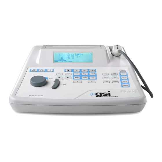
Introduction The GSI 39 Auto Tymp (hereafter referred to as ‘instrument’ in this guide unless otherwise noted for clarity) is a versatile combination instrument that provides testing capability for tympanometry alone, tympanometry combined with screening acoustic reflex measurements, and screening audiometry. - Page 20 GSI service technician. CAUTION The GSI 39 is designed to comply with the EMC requirements according to IEC 60601 1- 2 Radio transmitting equipment, cellular phones, etc. should not be used in the close proximity of the device since this could influence the performance of the device.
-
Page 21: Tympanometry And Gradient
Tympanometry and Gradient Tympanometry provides an objective means for determining the amount of mobility present within the eardrum and the ossicular chain. It is, however, important to keep in mind the fact that the amount of mobility present within the ossicular chain may be camouflaged by a scarred or thickened eardrum. Acoustic energy, commonly referred to as the probe tone (226 Hz or 1000 Hz) is introduced into a hermetically sealed ear canal by means of a loudspeaker located within the probe. -
Page 22: Gradient
Under this condition, no gradient measurement is possible. On the GSI 39, gradient measures are only calculated for the 226 Hz probe tone conditions. Screening Acoustic Reflex An acoustic reflex occurs when a very loud sound (stimulus) is presented to the auditory pathway. - Page 23 As these muscles contract, they stiffen their respective ossicular chains. This stiffening of the ossicular chain reduces the compliance of each middle-ear system. When the stimulus is presented to the same ear as the measurement, the test is referred to as an ipsilateral (same side) acoustic reflex test.
-
Page 24: Screening Audiometry
The GSI 39 allows for both manual and automated audiometry. For further details on automated audiometry, see Automatic Hearing Level in Chapter 3 of this guide. -
Page 25: Unpacking And Inspection
UNPACKING AND INSPECTION Examine the outside of the shipping container for any signs of damage. Notify the carrier immediately if any damage is noted. Carefully remove the instrument from its shipping container. Remove the plastic bag protecting the instrument. If the instrument appears to have suffered mechanical damage, notify the carrier immediately so that a proper claim can be made. -
Page 26: Combo Probe -Related Components
Combo Probe -related Components • Combo Probe (226 Hz / 1kHz Version) • Audiometry Headset, DD45 (Version 3 and Version 4) • Contralateral Insert Phone (Version 2 and Version 3) • Insert Phone Ear Tips (8 sizes, 4 each) (Version 2 and Version 3)* •... -
Page 27: Gsi 39 Initial Set Up
CAUTION Use only the GSI provided power supply. The GSI 39 provided power supply should only be connected to a power source meeting the following range 90-246VAC, 47-63Hz. In North America the power source should be a maximum of 120VAC. -
Page 28: Components
Components DISPLAY AND PRINTER Paper cover Probe holder Printer L C D Probe cable connector Probe PROBE (226 HZ) COMBO PROBE (226HZ AND 1KHZ) Page 28 of 112... -
Page 29: Rear Panel Labels And Connectors
REAR PANEL LABELS AND CONNECTORS NOTE: See Device Symbols Section for detailed descriptions WARNING Accessory equipment connected to the analog and digital interfaces must be certified to the respective IEC standards (IEC 950 for data processing or IEC 60601-1 for medical equipment). -
Page 30: Loading The Paper
Loading the Paper Remove the printer cover by placing fingers along the back edge of the printer and pulling upward on the cover. Cut the printer paper so that the leading edge of paper is straight across. Place the roll of paper inside the paper well so that the paper will unroll from the lower surface. -
Page 31: Operation
OPERATION 226 Hz Probe Indicators P1 - Yellow: The probe is occluded. Remove the probe and inspect for cause of occlusion. P2 - Green lamp: Blinking - The instrument is ready to begin a Tymp. Steady green - Test successfully started and in progress. P3 - Orange: A pressure leak has been detected. -
Page 32: Combo Probe Indicators (226 Hz And 1000 Hz Probe Tone)
The small 8 mm ear tips for the 1000 Hz option are used when doing a 1000 Hz probe tone test, which is assumed to be on an infant. Validation testing of the GSI 39 performed on infants showed that the 8 mm size tip was the best probe for that purpose. - Page 33 auto starts the pressure sequence and placing the probe in the ear canal when the pressurization begins can result in unwanted deflections in the tympanogram. The White Flat ear tips allow the user to place the probe and hold the Probe Tip at the entrance to the patient’s ear canal while the tympanogram and reflex testing are performed.
-
Page 34: Front Panel Controls And Indicators
Front Panel Controls and Indicators F2 F3 F9 F4 F10 F5 F11 F6 F7 F12 F22 F23 F28 F25 F27 F18 F16 F19 F17 F24 F26 Legend / Label Button Description Used to print the currently displayed page of memory or F1 / Print Screen active test screen. - Page 35 Legend / Label Button Description Selects Audiometry mode (Available in Version 3 & Version 4 F10 / Aud(iometry) only). When in Audiometry, this button starts the Auto HL when held for 3 seconds. Selects the DD45 calibration files for transducers. When the button is pressed, the display will flash to ensure that the user wants to change the transducer...
- Page 36 Legend / Label Button Description Used to indicate left ear is the test ear; so data stored in memory and/or printed is properly identified; for Versions 3 F19 / L and 4, used to select left earphone for audiometry. An L will appear on the LCD.
-
Page 37: Individual Display Formats
INDIVIDUAL DISPLAY FORMATS 226 Hz Tympanometry Screen 1.5 cm3 R daPa -400 ASHA Box Scale of Tympanogram Compliance Test Ear Ear Canal Volume Peak Amplitude Pressure at peak Gradient/Tympanogram width Pressure sweep scale in daPa 226 Hz Tympanometry/Reflex Screen 1.5 cm3 R 1000 daPa -400... -
Page 38: 1000 Hz Tympanometry Screen
1000 Hz Tympanometry Screen 5mmho mmho -400 0 +200 daPa Indicates 1000 Hz Probe Tone Scale of Tympanogram Compliance Test Ear Compliance Value at +200 daPa Peak Amplitude - C1 = Compensated Peak Amplitude Pressure at Peak Pressure Sweep Scale in daPa 5th Percentile * 50th Percentile of Peak Compliance * 95th Percentile of Peak *... -
Page 39: Audiometry Screen
Audiometry Screen 0 dB 1000 Hz ANSI - NBS 9A Auto HL M 125 500 2K 8K Hz Audiogram Display Test Ear Current Stimulus Intensity Current Stimulus Frequency Calibration information Tone Type Indicator Indicates Signal is being presented when displayed Patient Response Switch is being pressed M/A Denotes Manual or Auto HL Procedure Transducer currently selected (be sure the correct earphones are plugged in... -
Page 40: Tympanometry Testing Information
Tympanometry Testing Information It is good practice to perform a test on a normal ear each day to make certain that the instrument is functioning properly. See Biological Check section for details. Helpful hints Tympanometry and acoustic reflex testing can be performed on patients of any age; however, the technique used will vary with age. - Page 41 NOTE: Damage to the probe can result if fluid is sucked into the probe with negative pressure. 1. Place the appropriate size eartip onto the nose cone of the probe, making sure the rounded tip of the eartip sits flush with the tip of the nose cone (See Image below). Positioning the eartip (226 Hz only probe) 2.
-
Page 42: Combo Probe Insertion
canal wall causing an occlusion. It is best to remove the probe, examine the tip for cerumen and clean it if necessary. A change of eartip size may also be appropriate. Start the test again. Combo Probe Insertion Select the proper eartip and position it fully on the probe. The eartip should be pushed firmly onto the tip of the probe until it is fully seated. -
Page 43: Audiometry Testing (Version 3 And Version 4)
Audiometry Testing (Version 3 and Version 4) Prior to testing, ensure that the earphone cords are plugged into the appropriate connectors on the rear panel of the instrument. Both Headphones and Insert phones are available. Select the appropriate transducer and the desired tone type (i.e., pulsed, steady, or FM). CAUTION Always handle earphones with care. -
Page 44: Placement Of Insert Phones
PLACEMENT OF INSERT PHONES 1. Examine the ear canal for obstruction or excessive cerumen. 2. Make sure the sound tube is not blocked. 3. Place the black tubing of an ER-3A foam eartip completely onto the connector of the sound tube. -
Page 45: Tympanometry/Reflex Test Sequence
This section describes the test sequences for all modes of operation. Since there are five versions of the GSI 39, all of the test sequences described may not apply to this particular unit. If a test sequence is not available on a system, “Invalid” will display on the LCD screen. All systems are capable of being upgraded to add test modalities. - Page 46 The pressure sweep begins at the starting pressure of +200 daPa and proceeds in the negative direction at a rate of 600 daPa/second. Measurements of compliance are made continuously as the pressure sweep continues in the negative direction. The slope of the tympanogram increases as the measurement approaches the compliance peak.
-
Page 47: Tympanometry And Ipsilateral Reflex
TYMPANOMETRY AND IPSILATERAL REFLEX The default parameters for this test are tympanometry followed by an ipsilateral acoustic reflex test at 1000 Hz (2000 Hz for 1000 Hz probe tone). When a seal is obtained, the tympanometry sequence is initiated. (See topic Tympanometry only mode earlier in this chapter for details). -
Page 48: Temporary Programming Of Ipsilateral Acoustic Reflex Test Frequencies
The intensity levels available vary with the frequency selected ipsilaterally as follows: IPSILATERAL Intensity Levels IPSILATERAL Intensity Levels 500 Hz 80, 90 dB HL 500 Hz 80, 90, 100 dB HL 2000 Hz 85, 95 dB HL 1000 Hz 85, 95, 105 dB HL 4000 Hz 80, 90 dB HL 2000 Hz... -
Page 49: Tympanometry And Contralateral Reflex (Version 2 And Version 3)
TYMPANOMETRY AND CONTRALATERAL REFLEX (VERSION 2 AND VERSION 3) To select tympanometry and contralateral reflex testing: 1. Press the Tymp Reflex mode button. This initializes the GSI 39 to perform a tympanogram along with reflex measurements. The factory default setting for reflexes is 1000 Hz Ipsilateral presentation. - Page 50 For 1000 Hz Probe Tone, the reflexes will be measured at 0 daPa and a compliance change of ≥ 0.1 mmho is required. Up to 2 intensity levels per frequency are presented. NOTE: T he second or third intensity level presentations occur only if a response is not detected at the prior intensity level.
-
Page 51: Tympanometry And Ipsilateral/Contralateral Reflexes (Version 2 And Version 3)
TYMPANOMETRY AND IPSILATERAL/CONTRALATERAL REFLEXES (VERSION 2 AND VERSION 3) This test sequence can be selected either temporarily or set as the default sequence. If both ipsilateral and contralateral testing are performed only with certain patients, it is advisable to only change the test parameters temporarily on an as needed basis. -
Page 52: Exit Tympanometry/Reflex
screen. The format in which the ipsilateral and contralateral reflex test results are displayed is dependent upon the setting chosen in the Program mode. Exit tympanometry/reflex To exit Tymp Only Mode: Select Tymp Reflex or Audiometry Mode. Note that the appropriate screen appears on the display. To exit Tymp/Reflex Mode: Select Tymp or Audiometry Mode. -
Page 53: Audiometry Sequence (Version 3 And Version 4)
With one set of output jacks for the transducers, two buttons allow separate calibration files to be accessed. Be sure that the transducers that are connected to the back of the GSI 39 are the same as the selected transducer from the front panel. If Headphones are selected, a will appear in the center of the LCD. -
Page 54: To Change The Intensity Level Of The Test Tone
To change the intensity level of the test tone 1. Rotate the dB HL knob in the clockwise direction to increase the intensity level in 5 dB steps; rotate the knob in the counterclockwise direction to decrease the intensity level in 5 dB steps. The cursor on the audiogram moves up and down accordingly. -
Page 55: Screening Audiometry
10. Continue the procedure for all the desired frequencies. AUDIOMETRIC THRESHOLD The GSI 39 provides two ways to perform Audiometric Threshold testing. The system can be used in a Manual mode or an Automatic Hearing Level mode (Auto HL mode). In the Manual mode, the intensity, frequency and presentation of the stimulus are controlled by the tester. -
Page 56: Automatic Hearing Level
10 dB each time the patient presses the button and increased by 5 dB when the button is not pressed. The GSI 39 will present the stimulus and increase or decrease the intensity of the stimulus based on the patient response. The GSI 39 monitors the response/no response stimuli and determines the hearing threshold based on the data. -
Page 57: Performing The Auto Hl Procedure
Audiometric test results are stored in memory when is pressed. A total of 12 memory pages are available with the GSI 39. Each Tymp, Tymp/Reflex or individual ear in audiometry is assigned a page in memory. They are labelled M1 - M12. -
Page 58: Page Mode
Printing test results The printout will begin with a header, if it is selected, in the program mode (i.e., GSI 39 or a custom header). The next two lines contain space for recording the individuals name and the test date. This is followed by the test results in the order they were obtained/ selected. -
Page 59: Program Mode
PROGRAM MODE Program Mode To enter the program mode, press the PROGram button located on the front panel. There are two screens for the Program mode. To move to the second page, press the Increase Frequency button or turn the Attenuator knob until the cursor is next to the arrow on the bottom right column. -
Page 60: Program Menu Page 1 Option Descriptions
NOTE: The GSI 39 is available in 5 versions, each containing different testing modalities. When navigating through the Program menu, features that are not available on the GSI 39 version purchased will be represented by invalid on the LCD. -
Page 61: Newborn Nrm On 1K / Newborn Nrm Off 1K
NEWBORN NRM ON 1k / NEWBORN NRM OFF 1k For 1000 Hz Probe Tone, it is possible to have the normal box, as described by Margolis, et.al., appear on the tympanogram screen and printout. The NEWBORN NRM ON 1k is the factory default. The NEWBORN NRM ON 1k are represented on the display by dashed lines at the 5th or 95th percentile. -
Page 62: Reflex Display
Reflex Display Reflex test results can be displayed and printed in three different formats: REFLEX DB HL PLUS CURVE The default setting for this grouping is Reflex dB HL plus curve. All reflex test results will appear on the display and printout with the following information: a. -
Page 63: Reflex Yes/No
REFLEX YES/NO If Reflex yes/no is selected, the dB HL result will be replaced with the word yes (response detected at one of three levels) or no (no response detected). Display format for TYMP/REFLEX Test (Reflex test results given as Yes or No) When the reflex test cannot be performed, due to a leak or early extraction of the probe, a “NT”... -
Page 64: Auto Hl Setup
NOTE: 1000 Hz reflex stimulus is not available for the 1000 Hz probe option. This feature determines the stimuli and signal routing of the acoustic reflexes as default settings. To select the frequencies, move the cursor next to the selection and press the button to save. -
Page 65: Start Test Ear
Intensity Range (dB HL) Min. dB: 0* Return to Auto HL Set up Max dB: 90* NOTE: Setting the Min. dB range to 20 and the Max dB range to 45 allows a quick screening procedure using the Auto HL feature. Start Test Ear This submenu allows for the selection of the ear that will be tested first during the Auto HL procedure. -
Page 66: Language
LANGUAGE Six language selections are available. Use to highlight LANGUAGE and press the button to enter the Language submenu and then move the cursor to the language desired. Press the button to activate the selected language. The following languages are available. •... -
Page 67: Print - Audiogram/Print - Aud Table
Print - Audiogram/Print – Aud Table The audiometric test results can be printed out in an audiogram format (PRINT - AUDIOGRAM) or in a tabular format (PRINT - AUD TABLE). The default setting for this function is the print audiogram format. -
Page 68: Program Menu Page 2 Option Descriptions
4800 BAUD XON/XOFF ENABLED These settings are used to allow the data transfer from the GSI 39 to a computer. The settings must be the same on the GSI 39 and the computer. The factory defaults are defined by an *. -
Page 69: Prn Header Gsi/Prn Header Off/Prn Header Custom
This is the factory default setting for this feature. Each time the Print Screen or Print All tests in memory buttons are pressed, the printout will begin with the label GSI 39. PRINT HEADER OFF If this option is selected, no header will be printed before any test results, which will save space and printout time. -
Page 70: Reset To Defaults
RESET TO DEFAULTS This option will reset the programmable settings to the GSI factory defaults. Program Mode FACTORY DEFAULT SETTINGS AUDIOMETRY RESULTS - PRINT – AUDIOGRAM REFLEX RESULTS - REFLEX HL + CURVE 226 Hz Reflex - Ipsi 1000 Hz 1 kHz Reflex - Ipsi 2000 Hz NORMAL BOX... -
Page 71: Routine Maintenance
ROUTINE MAINTENANCE Pretest Tymp Checks A test cavity is provided with this instrument. This test cavity enables the ability to quickly verify, on a daily basis, the proper calibration of the unit.GSI strongly recommends that this quick check is a part of the daily routine. -
Page 72: Calibration Quick Check For 226 Hz
CALIBRATION QUICK CHECK FOR 226 HZ To initiate the quick check, select the Tymp only mode and insert the probe into the 0.5 cm opening on the test cavity. See Figure 1. The instrument is designed to start automatically, it is important that the probe is inserted as quickly and as smoothly as possible. -
Page 73: Calibration Quick Check For Combo Probe
CALIBRATION QUICK CHECK FOR COMBO PROBE To perform a calibration quick check with the 226 Hz probe tone using the Combo probe, follow the directions on the previous page. To initiate the quick check for the 1000 Hz probe tone, select the Tymp only mode and 1000 Hz probe tone from the front panel. -
Page 74: Altitude Adjustment
To keep a record of this test cavity calibration check, press the Print All button on the front panel of the instrument. Altitude Adjustment The altitude calibration adjustment enables a “correction” to the ear canal volume (ECV) measurement and test cavity volume measurement for variations due to altitude. The instrument is a pressure sensitive device that makes measurements relative to ambient air pressure. - Page 75 - Back to normal – The cursor will be next to Altitude - user check. Press to enter Altitude - user check. 1. When entering the altitude mode, the display will read as follows: Altitude Mode ECV 2.0 9.99 Standard 2.
-
Page 76: Pre-Test Audiometric Checks (Version 3 And 4 Only)
Pre-Test Audiometric Checks (Version 3 and 4 only) NOISE RECOVERY PERIOD Exposure to high levels of sound (e.g., unmuffled lawn mowers, loud music, and gunfire) tends to create a temporary threshold shift (TTS) which diminishes with time after exposure. Any subject/patient tested soon after such exposure may exhibit a hearing loss that does not reflect his or her normal hearing threshold. -
Page 77: Biological Check
Biological Check For Tympanometry and Reflex tests, the best way to determine that the instrument is operating properly is to perform a daily check on a normal ear – the operator’s ear if possible. This allows the operator to listen for the probe tone and the stimulus tone (during reflex) and to determine if the air pressure system is working properly. -
Page 78: Preventive Maintenance
Preventive Maintenance Preventive maintenance includes periodically cleaning and inspecting the exterior of the instrument. It is recommended that you develop a schedule for these purposes. Unless otherwise noted, the frequency of instrument cleaning can be determined by the user, depending on the conditions and frequency of use. -
Page 79: Cleaning Patient Contact Reusable Devices
CLEANING PATIENT CONTACT REUSABLE DEVICES To help insure patient safety, prevent cross infection and provide effective service, GSI devices must be properly maintained. Maintenance should include cleaning patient contact parts prior to each use. The earphone cushions and patient hand switch can be wiped with a slightly damp cloth containing soap and water ammonia based cleaners or bleach based cleaners. -
Page 80: Probe Care - 226 Hz Probe
Probe Care – 226 Hz Probe With normal use, cerumen can work its way inside the probe nose cone (probe tip). During the warm- up period each day and throughout the day, inspect the probe tip to make sure it is clean and free of cerumen. -
Page 81: The O-Ring
The O-Ring There is an O-Ring seated at the end of the threads on the probe. As a preventative maintenance measure, and to ensure that the nose cone of the probe unscrews easily, do not clean or remove the lubricant from the O-Ring. If the O-Ring appears to be void of any lubricant, or if the nose cone itself was difficult to remove, apply a high-quality synthetic lubricant such as those considered “food- grade.”... -
Page 82: Probe Reassembly
Probe reassembly After cleaning, reassemble the probe nose cone to the probe body by screwing the cone back onto the probe. Take care to align the threads on both the probe body and the nose cone before screwing the pieces together. Only screw the nose cone on until it is finger tight. It may be helpful to gently squeeze the two sides of the probe case together while screwing the nose cone into place. -
Page 83: Probe Care - Combo Probe Tip
Probe Care - Combo Probe Tip To ensure measurement accuracy, it is essential to clean the probe tip daily to be certain that the tubes are clean and free of cerumen. If the lights on the probe are indicating an occlusion, cleaning the probe tubes will most likely rectify the situation. - Page 84 WARNING Avoid getting the probe moist. Do not use the probe tip if it is wet or damp because the moisture may make its way to the sensitive electronic equipment at the end of the tygon tubing. Page 84 of 112...
-
Page 85: Earphone Care (Versions 3 And 4 Only)
Earphone Care (Versions 3 and 4 only) With proper care, the earphone and cords provided with the instrument (Versions 3 and 4) should last a long time. Moisture should not be allowed anywhere near the earphone itself as this will damage the diaphragm and grill cloth, requiring its replacement. -
Page 86: Paper Supply
Paper supply To streamline each testing session, it is a good idea to check the amount of paper left inside the printer compartment. Extra rolls of paper should be kept nearby. NOTE: The number of tests per roll of paper will vary with the version Auto Tymp being used and the type of tests being performed. -
Page 87: Test Results
TEST RESULTS Ear canal Volume – 226 Hz Probe Tone NORMAL As a general rule, values for ear canal volume should be between 0.2 and 2.0 cm . However, the normal values will vary with age and bone structure. ABNORMAL An ear canal value of less than 0.2 cm indicates an abnormal condition. -
Page 88: Compliance Peak
Compliance Peak NORMAL The range of normals for compliance is 0.2 cm to approximately 1.4 cm . Some protocols use a larger range up to 1.8 cm . A measured compliance peak within this range indicates normal mobility within the middle-ear system. ABNORMAL A compliance value of less than 0.2 cm indicates a pathological condition as the middle-ear system is... -
Page 89: Pressure Peak
Pressure Peak NORMAL Strict rules for middle-ear pressure indicate a normal range of ± 50 daPa. However, for most applications, a normal range of -150 daPa to +100 daPa is used. ABNORMAL Very rarely, an extreme positive pressure condition will be observed. Some researchers have reported high positive pressures at the onset of acute otitis media. -
Page 90: Acoustic Reflex
Acoustic reflex NORMAL For screening purposes, an ipsilateral or contralateral reflex measured at any one of the levels available per frequency can be considered normal. Obviously, the lowest values are desired. However, without knowing the hearing threshold level of the individual per frequency, it is difficult to make a more definite statement. -
Page 91: Special Messages And Error Codes
Special Messages and Error Codes Error code numbers and other special messages may be displayed on the screen or on the printout. These messages appear whenever an instrument error occurs or, in some instances, to apprise the operator of certain situations. For example, if there is no test result on the screen and the Print Screen button is pressed, the printer will indicate “No Test to Print”... -
Page 92: Sample Test Results
Sample Test Results Figures 1 through 8 illustrate test results from sample GSI 39 Auto Tymp printouts. The smoothness of the tympanogram tracing is determined by the amount of movement during the testing. Little or no movement during the testing provides a smoother tracing. Moving, talking or crying during testing leads to a more erratic traces but does not dramatically affect the test results. - Page 93 Figure 4: 226 Hz Abnormal Tympanogram Figure 5: 226 Hz Abnormal Tympanogram Figure 6: Infant Normative Data Infant Normative Data Legend for Figure 6 daPa mmho y + 200 daPa y Peak Values Pressure at Peak 5% 0.8 5% 1.2 5% -133 50% 1.4 50% 2.5...
- Page 94 Figure 7: 1000 Hz Abnormal Figure 8: 1000 Hz Abnormal Page 94 of 112...
-
Page 95: Computer Interface
COMPUTER INTERFACE Introduction WARNING This equipment is intended to be connected to other equipment thus forming a Medical Electrical System. External equipment intended for connection to signal input, signal output or other connectors must comply with the relevant product standard e.g. IEC 60950-1 for IT equipment and the IEC 60601- series for medical electrical equipment. -
Page 96: No Data Available
Data Transfer Program Mode The Data Transfer Program mode is used to modify the GSI 39 USB interface configuration parameters to match the computer’s USB Port settings. Enter the Program mode by selecting the PROGram button. Move the cursor to Data Xfer Config and press the button to enter the submenu. -
Page 97: Computer Interface
The configuration of the GSI 39 computer interface must be set to match the interface configuration of the computer. The GSI 39 defaults to 115 kBaud, no parity, 8 data bits, 2 stop bits and no communications flow control. The default settings for the baud rate, parity, number of data bits and flow control may be modified using the Data Transfer Program Mode explained earlier in this chapter. -
Page 98: Uploading Data From The Gsi 39 To Gsi Suite
Enter the patient information (name, date of birth, ID). 3. Prior to testing the new patient, all data must be erased. Press the M-- on the GSI 39 to erase all data. Not doing this step may result in mixing test results from different sessions and/or patients. -
Page 99: Appendix A - Technical Data
APPENDIX A - TECHNICAL DATA Standards IEC/EN 60601-1 Medical Electrical Equipment Requirements for Safety CSA C22.2 No.601-1-M90 ANSI S3.39-1987 Aural Acoustic Impedance Admittance (Type 3) IEC 60645-5 Aural Acoustic Impedance/ Admittance (Type 3) ANSI S3.6-2004 Audiometers (Type 4) IEC 60645-1 Pure Tone Audiometers (Type 4) 2004 Specifications for Audiometers (Type 4) PTB Certificate No. -
Page 100: Appendix B: Secifications
APPENDIX B: SECIFICATIONS Tympanometry Modes Probe Tone: 226 Hz, ±2% 1000 Hz ±2% Sound Pressure Level: 226 Hz: 85.5 dB SPL, ±2.0 dB, measured in a 2.0 cm coupler 1000 Hz: 75 dB SPL, ±2.0 dB, measured in a 2.0 cm coupler Harmonic Distortion: <3%... -
Page 101: Acoustic Reflex Stimuli
NOTE: High compliance tympanograms will take somewhat longer. Gradient: 226 Hz only: Measurement of the tympanogram width taken at 50% of peak compliance. Acoustic Reflex Stimuli F requencies: 226 Hz Probe Tone: 500, 1000, 2000, and 4000 Hz for both ipsilateral and contralateral stimulation 1000 Hz Probe Tone: 500, 2000 and 4000 Hz for both ipsilateral and contralateral stimulation... -
Page 102: Probe Led Indicators
4. Contralateral is available with Versions 2 and 3 only. Pressure: 226 Hz Probe Tone: Reflex measures are set automatically to pressure at peak compliance with an offset of -20 daPa if peak pressure is negative and +20 daPa if peak pressure is positive. 1000 Hz Probe Tone: Reflex measures are taken at 0 daPa regardless of peak pressure. -
Page 103: Intensity Levels
INTENSITY LEVELS DD45 Headphones Insert Phones 125 Hz -10 to 50 dB HL 125 Hz -10 to 40 dB HL 500 to 4000 Hz -10 to 90 dB HL 500 to 4000 Hz -10 to 80 dB HL 6000 Hz -10 to 85 dB HL 6000 Hz -10 to 70 dB HL... -
Page 104: Power
Power Line Voltage: 100 - 240 VAC (±10%) NOTE: Desktop power supply. Frequency Range: 47 - 63 Hz (±5%) Power Consumption: 16 watts maximum while printing. Low voltage input for desktop power supplies 7 VDC, 3.0 A. Display: 240 x 64 graphical, monochrome LCD Environmental Temperature Operating:... -
Page 105: Appendix C: Glossary Of Terms
APPENDIX C: GLOSSARY OF TERMS Acoustic Reflex – Reflexive contraction of the stapedius muscle in response to loud sound. Automated Audiometry (Auto HL) – Automated measurement of hearing that allows the listener to control the intensity with a hand switch. Compliance Peak - The point of maximum mobility in a tympanogram, which indicates the degree of mobility within the middle-ear system. -
Page 106: Appendix D: Bibliography
APPENDIX D: BIBLIOGRAPHY American Speech-Language-Hearing Association (1990). “Guidelines for Screening for Hearing Impairment and Middle Ear Disorders”. ASHA, 32 (Suppl.2), 17-24. Criteria for Permissible Ambient Noise During Audiometric Testing (ANSI S3.1 - 1977). de Jonge, R.R. (1986). “Normal Tympanometric Gradient: A Comparison of Three Methods”. Audiology, 26, 299-308. -
Page 107: Appendix E: Electromagnetic Compatibility (Emc)
GSI 39 according to the EMC information presented in this chapter. The GSI 39 has been tested for EMC emissions and immunity as a stand-alone device. Do not use the GSI 39 adjacent to or stacked with other electronic equipment. If adjacent or stacked use is necessary, the user should verify normal operation in the configuration. -
Page 108: Guidance And Manufacturer's Declaration Electromagnetic Emissions
The GSI 39 is intended for use in the electromagnetic environment specified below. The customer or the user of the GSI 39 should assure that it is used in such an environment. This instrument is in compliance with IEC60601-1-2:2014, emission class B group 1... -
Page 109: Recommended Separation Distances Between Portable And Mobile Rf Communications Equipment
Recommended separation distances between portable and mobile RF communications equipment The GSI 39 is intended for use in an electromagnetic environment in which radiated RF disturbances are controlled. The customer or the user of the GSI 39 can help prevent electromagnetic... -
Page 110: Guidance And Manufacturer's Declaration Electromagnetic Immunity
135, 180, 225, 270 and 100% reduction for 1 environment. If the user of lines 315 degrees) cycle the GSI 39 requires IEC 61000-4-11 Dips: 100% reduction continued operation during for 1 cycle (voltage 30% reduction for power mains interruptions, it... - Page 111 To assess the electromagnetic environment due to fixed RF transmitters, an electromagnetic site survey should be considered. If the measured field strength in the location in which the GSI 39 is used exceeds the applicable RF compliance level Page 111 of 112...
- Page 112 GSI 39 should be observed to verify normal operation, If abnormal performance is observed, additional measures may be necessary, such as reorienting or relocating the GSI 39. Over the frequency range 150 kHz to 80 MHz, field strengths should be less than 3 V/m.
Need help?
Do you have a question about the gsi 39 and is the answer not in the manual?
Questions and answers
can you tell me what M12 error code relates to please