
Related Manuals for Anywire ASLINK B2G78-PB1

Summary of Contents for Anywire ASLINK B2G78-PB1
- Page 1 Anywire Corporation AnyWireASLINK System PROFIBUS Gateway B2G78-PB1 User’s Manual Version 1.5 August 6, 2019 AnyWireASLINK System PMA-10725AG-EN PMA-18204AA...
- Page 2 [Application of the product] WARNING Application of the AnyWire system is limited to areas in which any failure and/or problem of the product shall not result in serious consequences and in systems with fail-safe and backup functions are provided externally.
- Page 3 [Precautions for installation] WARNING AnyWire products should be used in environments that meet the general specifications presented in the User’s Manual. Using them in environments outside the general specifications may result in injuries due to electric shock, fire, malfunctions and/or damage to or degradation of the products.
- Page 4 Do not turn on the 24 V DC power source before completing wiring and connections of the whole Anywire system. Use a 24 V DC direct current stabilized power supply for Anywire system devices. Do not bind the control wire and communication cable with the main circuit or power line, or do not bring them close to each other.
- Page 5 [Precautions for startup and maintenance] WARNING Do not touch the terminals while the power is on. Electric shock or malfunction may result. To clean or to re-tighten the screws on the terminal block and the unit mounting screws, make sure to shut off all phases of the external supply power used in the system.
-
Page 6: Table Of Contents
4.6 Transmission cable type and precautions ································································ 4-7 4.7 Transmission line supply current value ··································································· 4-8 4.8 Terminator ······································································································· 4-9 4.9 AnyWire filter ·································································································· 4-10 4.10 Address setting (reference) ·············································································· 4-12 5. Input/output data ··································································································· 5-1 5.1 Input memory map ····························································································· 5-1 5.2 Output memory map···························································································... - Page 7 12. Warranty ········································································································· 12-1 13. RoHS Directive for the Chinese version ·································································· 13-1 14. Change history ································································································· 14-1...
-
Page 8: Overview
Overview 1. Overview The B2G78-PB1 operates as a gateway unit for the PROFIBUS and AnyWireASLINK. The AnyWireASLINK system can be connected to the PROFIBUS by using this gateway. The AnyWireASLINK system is a “Sho-Haisen” (wiring saving) system consisting of compact and fewer-point/multiple-distribution units suitable for wire saving on the sensor level. -
Page 9: Specifications
Pollution degree 2 or less *1 Do not use or store the AnyWire ASLINK equipment in an environment pressurized more than the atmospheric pressure at 0 m altitude. Failure to observe this instruction causes malfunction of the equipment. *2 Index indicating a degree of conductive substance generation under the equipment operating environment. -
Page 10: Performance Specifications
Transmission method DC power supply superimposed total frame, cyclic method Synchronization Frame/bit synchronization Transmission protocol AnyWire ASLINK protocol Maximum number of bits 512 points (256 inputs, 256 outputs) Number of connectable units 128 units max. Transmission distance / Cable diameter... -
Page 11: Outside Dimensions
Specifications 2.3 Outside dimensions Unit: mm... -
Page 12: Name Of Each Part
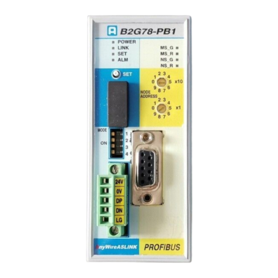
Specifications 2.4 Name of each part LED display SET switch Node address setting switch Monitor connector Transmission point number PROFIBUS connector setting switch terminal block AnyWireASLINK connector terminal block... -
Page 13: Attaching To/Detaching From Din Rail
Specifications 2.5 Attaching to/detaching from DIN rail Please install this device to the DIN rail before use. Vertical installation 1. How to attach to the DIN rail Hang the fixed hook on the upper part of the bottom surface on the DIN rail. ... -
Page 14: Switch Settings
Switch settings 3. Switch settings 3.1 Address setting switch Set the address by using the address setting switch. Do not change the address while the unit is in operation. Address Address setting switch 3.2 Communication speed setting The communication speed on the PROFIBUS side is not set because it is according to the automatic follow function. -
Page 15: Registration Of Slave Module
Switch settings 3.4 Registration of slave module Register the slave module of this unit according to the number of transmission points on the AnyWireASLINK side. Total number of Module (registration order) transmission points 64 points Status input 4 words Status input 2 words Command output 4 words Command output 2 words Input 2 words... -
Page 16: Set Switch
Switch settings Module registration example for a total of 512 transmission points 3.5 SET switch This switch is for performing error flag clear, and automatic address recognition for the AnyWireASLINK slave unit. (1) Error flag clear Pressing the SET switch clears the error flag. This is the same operation as clearing the error flag of the output memory. -
Page 17: Anywireaslink
AnyWireASLINK 4. AnyWireASLINK 4.1 System configuration The AnyWireASLINK system consists of a master unit, slave units and their peripheral devices. Gateway Slave unit Terminator output input output input... -
Page 18: Slave Units
AnyWireASLINK 4.2 Slave units Types of slave units This product uses slave units for the AnyWireASLINK system. The following types of slave units can be used. Unit type Slave I/O terminal ASLINK terminals and the like Analog terminal Analog input unit and the like Sensor/amplifier ASLINK sensor and the like Other hardware... -
Page 19: Transmission Line (Dp-Dn)
AnyWireASLINK 4.3 Transmission line (DP-DN) The “AnyWireASLINK Protocol” is a low speed transmission clock that can also achieve effective high-speed transmission making it compatible with a wide range of cable characteristics, and therefore allows for various transmission cables and general-purpose electric wires to be used as transmission channels. - Page 20 AnyWireASLINK When a terminal block is used A cable can be branched as follows using a commercially available terminal block (a terminal block in which terminals that face each other are internally connected). Branching between cabtyre cables Conversion to a dedicated flat cable ...
- Page 21 AnyWireASLINK Tree-branching method The tree-branching method is a way to re-connect a T-branched branch line using the T-branching method or multi-drop method. Actual wiring is the same as the T-branching method and the multi-drop method. Star-branching method The star-branching method is a way to connect the master unit and lay cable radially from a certain branching point to connect the slave unit.
-
Page 22: Transmission Distance
AnyWireASLINK 4.5 Transmission distance All transmission distances described for the AnyWireASLINK refer to the “total length” of a cable. Total length is the total cable length to be used including branches. Wiring of the AnyWireASLINK system can be established with only two transmission lines (DP, DN). The two transmission lines (DP, DN) support a maximum total length of 200m. -
Page 23: Transmission Cable Type And Precautions
, rated temperature 70ºC) CAUTION Shielded cable Since AnyWire has high noise resistance, it is unnecessary to use shielded cable. Please note that if the shielded cable shielding is not properly grounded, it may result in problems during use. -
Page 24: Transmission Line Supply Current Value
AnyWireASLINK Electric wiring example Type Image Specifications 300V vinyl JIS C3306 cabtyre cable Cross-section area: 0.75mm (VCTF) Allowable current: 7A (30ºC) Conductor resistance: 25.1Ω/km (20ºC) or less Insulation resistance: 5MΩ/km (20ºC) or more Dedicated flat cable Cross-section area: 0.75mm (HKV) Allowable current: 7A Model: FK4-075-100... -
Page 25: Terminator
AnyWireASLINK 4.8 Terminator This unit incorporates a circuit which shapes the transmission waveform, and functions to avoid situations where the transmission waveform is disturbed by the external environment. Make sure to properly connect it to the transmission line as it has a polarity. (DP: Red, DN: Black) Reverse connection may result in transmission fault. -
Page 26: Anywire Filter
AnyWireASLINK 4.9 AnyWire filter If any of the parallel lines of DP, DN, 24V, or 0V exceeds the total length of 50m in a power supply system to be supplied, connect in series the “ASLINK filter [Type ANF-01]” or a “COSEL filter [Type EAC-06-472]” to 24V and 0V in the starting position of the parallel lines. - Page 27 AnyWireASLINK ASLINK filter (ANF-01) connection example when there is a local power supply AnyWireASLINK master General-purpose power supply filter (Use if necessary) 24V DC stabilized power supply Two-wire terminal If any of the parallel lines of Four-wire terminal DP, DN, 24V, or 0V exceed a total length of 50m Four-wire terminal Two-wire terminal...
-
Page 28: Address Setting (Reference)
AnyWireASLINK 4.10 Address setting (reference) The “Address setting” of a slave unit is determined by which number bit (in order) in the AnyWireASLINK transmission frame the slave unit is associated with. Each terminal occupies the location of its own point number (with the set address number placed at the beginning) from that position. -
Page 29: Input/Output Data
Input/output data 5. Input/output data 5.1 Input memory map bit No. Offset byte address Number of units connected Number of alarms Number of errors - - - - Latest error code - - - - Latest error occurrence ID Status details Sensing level The numbers from 0 to 255 in the list indicate AnyWireASLINK addresses. -
Page 30: Output Memory Map
Input/output data 5.2 Output memory map bit No. Offset byte address - - - - - - - - - - - - - - - - - Access target ID - - - - - - - - - -... -
Page 31: Latest Error Code/Latest Error Occurrence Id
Input/output data 5.3 Latest error code/Latest error occurrence ID It is possible to check the latest error code and target ID that the B2G78-PB1 detected. The latest error code list is as follows: Error code Name Error occurrence Countermeasures taken by customer Transmission As this error is The cause may be insufficient voltage of the... - Page 32 Input/output data Error code Name Error occurrence Countermeasures taken by customer DP, DN Error ID is stored. The DP, DN signal lines may be disconnected, disconnection or there may be no response from slave units. error The system configuration may have been changed after slave unit failure or automatic address recognition.
- Page 33 Input/output data Error code Name Error Countermeasures taken by customer occurrence ID Parameter access As this error is Parameter access has been performed for an ID target ID error not dependent whose address has not been automatically on individual recognized. Narrow down error IDs by checking slave units, the the alarm ID information in the memory.
-
Page 34: Status Details
Input/output data 5.4 Status details The status details are in the following format: Status details data ⑯ ⑮ ⑭ ⑬ ⑫ ⑪ ⑩ ⑨ ⑧ ⑦ ⑥ ⑤ ④ ③ ② ① ① Unit power supply status (common) Bit status Meaning Slave unit voltage drop No error... -
Page 35: Status Details/Sensing Level Access Method
Input/output data 5.5 Status details/sensing level access method After storing data of access target IDs, turn on the slave access request command to store details of the designated slave unit status and sensing level. <Access target ID> The ID format is as follows: (Type) Address (0x00 to 0xFE) Type: 00: Output, 01: Input (input/output mixed) -
Page 36: Monitoring Function
Monitoring function 6. Monitoring function 6.1 Overview AnyWireASLINK slave units have their own addresses, and when this machine sends out an address, a response from the slave unit with that address allows for disconnection detection and verifies the existence of the slave unit. This machine stores the addresses of the slave units that are connected at the time via the automatic address recognition operation (described later) into EEPROM. -
Page 37: Led Display
LED display 7. LED display Power supply LED display : Lit/Flashing : Unlit Color Name symbol POWER Green Power status Lit Power is ON. Power is OFF. PROFIBUS side LED display : Lit/flashing : Unlit Color Name symbol ST_G Green Status Normally operating Power is OFF, or check the status of ST_R as there is an error. -
Page 38: Connections
Connections 8. Connections 8.1 Connectors 8.1.1. PROFIBUS connector Connect with a D-sub 9 pin type PROFIBUS dedicated connector. Signal name Description Pin no. RxD/TxD-P Data reception/transmission: Line B (red) CNTR-P Control of repeater direction DGND Data earth (reference voltage for VP) +5V power (example: for bus termination) RxD/TxD-N Data reception/transmission: Line A (green) -
Page 39: Monitor Connector
Connections 8.1.3. Monitor connector This is a connector for connecting a debugging monitor. Signals are RS232 compatible. Connector: Manufactured by JST Housing: XHP-5 Contact: BXH-001T-P0.6 When making an extension cable D-sub 9-pin MRXD male MTXD * Connect the above extension cable and the personal computer with a cross cable. -
Page 40: Required Transmission Time
Required transmission time 9. Required transmission time 9.1 Double check AnyWireASLINK does not update input area data unless it receives the same data consecutively twice (double check). For data update, therefore, it needs a transmission cycle time of one cycle at least and of two cycles at maximum. -
Page 41: Maximum Transmission Delay Time
Connections 9.2 Maximum transmission delay time The transmission delay time from the input to the output is as shown in the following illustration. Input Output Input/output equipment Input equipment response time Output equipment response time Input slave response time Output slave response time (Processing time) (Processing time) [3] Transmission cycle time... -
Page 42: Device Profile
Device profile 10. Device profile Use the following GSD file. ANYW0F31.gsd GSD files can be downloaded from the AnyWire Homepage. http://www.anywire.jp Top page>Support & Download>Download>Software 10-1... -
Page 43: Troubleshooting
Troubleshooting 11. Troubleshooting 11.1 Visual check Each unit has an LED status display function so that errors related to the operating state of the unit or communication can be narrowed down by checking the LEDs. When any LED displays an error, review the setting and wiring to correct the error. (1) Check the LED state of the gateway. -
Page 44: Check Using Input/Output Data
Troubleshooting (2) Check the LED state of the slave unit 1. Check the “LINK” LED. Flashing Normal If the LED is not flashing, refer to P11-4 and remove the cause of the error. P11-4 2. Check the “ALM” LED. Unlit ... -
Page 45: Led State Of The Gateway
Troubleshooting 11.3 LED state of the gateway (1) When the “ALM” LED is lit or is flashing “ALM” flashes slowly (every second): DP-DN short-circuit error Items to check Description of measures Check that the transmission line (DP, DN) is Check that the transmission line (DP, DN) is not not short-circuited short-circuited. -
Page 46: Led State Of The Slave Unit
Troubleshooting 11.4 LED state of the slave unit The slave unit also has a status display function using LEDs. The display status and primary causes are described respectively. (1) When “LINK” is lit The slave unit is not receiving transmission signals. (Transmission waveform error) Under normal conditions, a voltage of approximately 17V to 18V is observed when measuring between transmission lines (DP-DN) using a tester in DC mode. - Page 47 (1) Misuse or abuse of the Product by the owner; (2) Faults due to a cause other than the delivered Product; (3) Unauthorized modification or repair of the Product by any party other than Anywire; (4) Any act of God, disaster, or other cause beyond the control of Anywire.
- Page 48 RoHS Directive for the Chinese version 13. RoHS Directive for the Chinese version 电子信息产品上所示标记是依据 SJ/T11364-2006 规定,按照电子信息产品污染控制标识要求制定。 本产品的环保使用期限为 10 年。 如果遵守产品说明书中的操作条件使用电子信息产品, 不会发生因产品中的有害物质泄漏或突 发异变而引发严重的环境污染,人身事故,或损坏财产等情况。 的产品中有害物质的名称及含量 部件名称 有害物质 铅 汞 镉 六价铬 多溴联苯 多溴二苯醚 (Pb) (Hg) (Cd) [Cr(VI)] (PBB) (PBDE) 安装基板 ...
- Page 49 May 6, 2016 Standardization of structure, additions August 24, 2016 “4.2 Slave units” Updated content “4.9 AnyWire filter” Corrected allowable current from 10A to 5A “2.2 Performance specifications” Corrected the transmission cycle time May 25, 2017 “4.2 Slave units” Updated content...
- Page 50 Anywire Corporation Headquarters: 1 Babazusho, Nagaokakyo-shi, Kyoto 617-8550 JAPAN Website: http://www.anywire.jp E-Mail inquiry: info_e@anywire.jp...
Need help?
Do you have a question about the ASLINK B2G78-PB1 and is the answer not in the manual?
Questions and answers