
Related Manuals for SystemAir RS Series


Summary of Contents for SystemAir RS Series
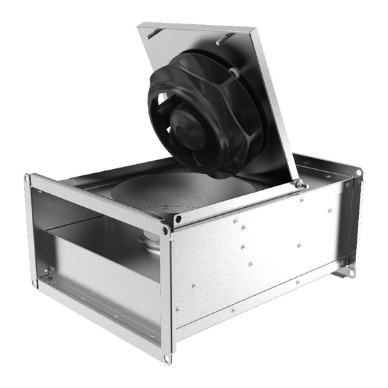
- Page 1 Installation, Operation and Maintenance instruction KE Rectangular duct fan KT Rectangular duct fan RS Rectangular duct fan AC/EC RSI Rectangular duct fan AC/EC...
-
Page 2: Table Of Contents
Table of content 1 Introduction ............1 12.2.1 Product dimensions KE fans and KT fans ..........13 Product description ........1 12.2.2 Product dimensions RS fans, RS Intended use ..........1 EC fans ........14 Document description........1 12.2.3 Product dimensions RSI fans, RSI Product overview......... -
Page 3: Introduction
The procedures must be done by approved personnel only. Intended use Speak to Systemair for more information on how to install the product in different installation locations. The product is intended for transportation of clean or conta- minated air with a maximum temperature of 60–70 °C. -
Page 4: Name Plate
• The product is incorrectly installed, operated or maintained. Systemair is not liable for damages that the product causes in these conditions: Use a mobile device to scan the scannable code and go to the Systemair documentation portal for more documentation and document translations. -
Page 5: Safety
• The product is repaired with parts that are not original Safety spare parts from Systemair. • The product is used together with accessories that are not Safety definitions original accessories from Systemair. Warnings, cautions and notes are used to point out specially •... -
Page 6: Personal Protective Equipment
–10 and +30 °C. A stable ambient • Sound levels exceeding 70 dB(A) may occur depending temperature prevents damage from condensation. on model and size. Visit www.systemair.com for more de- tailed information about your product. • Keep the product in storage for maximum 1 year. -
Page 7: Installation
– To decrease vibrations transmitted from the product to the duct system, Systemair recommends to install vi- bration dampers, fast clamps or flexible connections. – If you install the product with free suction or free dis- charge, it is necessary to install a protection grille. -
Page 8: Electrical Connection
Guide rails are not supplied by To do before the electrical Systemair. connection • Make sure that the electrical connection agrees with the product specification on the motor name plate. -
Page 9: To Install Motor Protection For Ac Motors
• Install the motor cables and the temperature monitor apart. value that is given on the name plate. • If the motor does not have temperature monitors, install a The commissioning report is found at www.systemair.com. motor protection switch. To do before the commissioning •... -
Page 10: Operation
EC motors must be set to ON/OFF via the control input. To stop the product via mains supply decreases the life time of the motor. Systemair recommends to install external speed controller for easy access to control the input signal. -
Page 11: To Clean The Product
Spare parts • For information about spare parts, send an e-mail to support@systemair.com. • For more information about spare parts, contact Systemair support. • Always use spare parts from Systemair. • When you send an order for spare parts, include the serial number of the product. -
Page 12: Troubleshooting
Troubleshooting Note: If you cannot find a solution to your problem in this section, speak to Systemair technical support. Problem Cause Solution The fan impeller is not correctly Speak to Systemair technical support. balanced. There is dirt on the fan impeller. - Page 13 This is not applicable for EC motors or 3–phase AC motors. There is blockage in the motor. Speak to Systemair technical support. Defective motor winding. If it is possible, measure the resistance to do a check of the motor winding.
-
Page 14: Disposal
Disposal 10.1 To disassemble and discard the parts of the product The product follows the WEEE directive. This symbol on the product or the packaging of the product shows that this Disconnect and disassemble the product in the opposite product is not domestic waste. The product must be recycled sequence of electrical connection and installation. -
Page 15: Warranty
12.1 Technical data overview Max. temperature of transported air, °C Max. ambient temperature, °C Refer to the data sheet in the online catalogue at www.systemair.com. Sound pressure, dB IP class Voltage, current, frequency, enclosure Refer to the name plate. Refer to 1.5 Name plate page 2... -
Page 16: Product Dimensions Rs Fans, Rs Ec Fans
ØH KE 50–24–4** KE 50–30–6** KE 60–30–6** KT 40–20–4 KT 50–25–4/6 KT 50–30–4** KT 60–30–4/6 KT 60–35–4/6 KT 70–40–4/6 KT 80–50–6 1090 KT 100–50–6** 1040 1020 1140 ** after the product name means that the product is sold outside EU. 12.2.2 Product dimensions RS fans, RS EC fans Note:... - Page 17 The dimensions are split over 2 separate tables. See Table 2 for measures I-O Table 1 ØG RS 30–15 sileo RS 40–20 M sileo RS 40–20 L sileo 310.5 352.5 352.5 RS 50–25 sileo 85.5 RS 60–35 M1 sileo RS 60–35 M3 sileo RS 60–35 L1 sileo RS 60–35 L3 sileo RS 70–40 L1 sileo...
-
Page 18: Product Dimensions Rsi Fans, Rsi Ec Fans
Table 1 (continued) ØG RS 60–35 EC sileo RS 70–40 EC sileo RS 80–50 EC sileo 182.5 RS 100–50 EC sileo Table 2 c-c L c-c N RS 30–15 sileo RS 40–20 M sileo RS 40–20 L sileo RS 50–25 sileo RS 60–35 M1 sileo RS 60–35 M3 sileo RS 60–35 L1 sileo... - Page 19 The dimensions are split over 2 separate tables. See Table 4 for measures J-P Table 3 ØA c-c I RSI 60–35 M1 92.5 99.5 139.5 347.5 RSI 60–35 M3 RSI 60–35 L1 RSI 60–35 L3 92.5 99.5 139.5 347.5 RSI 70–40 L1–L3 RSI 80–50 M3 RSI 80–50 L3 112.5...
-
Page 20: Wiring Diagrams
Table 4 (continued) c-c N RSI 70–40 EC sileo 55.5 RSI 80–50 EC sileo 55.5 RSI 100–50 EC sileo 55.5 1020 1041 1108 12.3 Wiring diagrams Abbreviation in wiring diagram Cable colour Yellow Blue White Green Brown Black Grey Green/Yellow 12.3.1 Wiring diagrams for AC fans KE fans... -
Page 21: Wiring Diagrams For Ec Fans
KT fans RS fans RSI fans 3–phase 230 V KT 50–25–4 RS 60–35 L3 RSI 60–35 L3 KT 50–25–6 RS 60–35 M3 RSI 60–35 M3 KT 50–30–4** RS 70–40 L3 RSI 70–40 L3 KT 60-30–4 RS 80–50 L3 RSI 80–50 L3 KT 60–30–6 RS 60–35 M3 RSI 60–35 M3... -
Page 22: Wiring Diagrams For Speed Controller For Ac Motors
RS EC RSI EC 1–phase 230 V RS 30–15 EC RSI 60–35 EC RS 40–20 EC RSI 70–40 EC RS 50–25 EC RS 60–35 EC RS 70–40 EC RS EC 3–phase 400 V RSI EC RS 80–50 EC RSI 80–50 EC RS 100–50 EC RSI 100–50 EC 0-10V DC... - Page 23 Relay connection. There is always 230 V between ~ and N when the transformer knob is in one of the positions 1–5. Mains supply C. Earth D. Fan REE — Thyristor REE 1 and REE 2 - Surface mounting or with flush mounting casing included.
- Page 24 RTRE Manual 5-step transformer with motor protection. RTRE 1,5 RTRE 3 RTRE 5 RTRE 7 RTRE 12 Relay connection. There is always 230 V between ~ and N when the transformer knob is in one of the positions 1–5. Mains supply C.
- Page 25 Contact rating, maximum AC 250 V/2 A Mains supply, 1–phase 208...277 V, 50/60 Hz C. Motor with internal thermal contacts D. OFF/ON RTRD A 3-phase transformer that controls the fan speed by altering the supply voltage in five fixed steps. The steps are adjusted by using the control knob on the front of the unit.
-
Page 26: Wiring Diagrams For Speed Controllers For Ec Motors
RTRDU Manual 5–step transformer with motor protection — a 3–phase transformer that controls the fan speed by altering the supply voltage in five fixed steps. The steps are adjusted by using the control knob on the front of the unit. RTRDU FS FS TB TB... - Page 27 MTP 20 MTP 20 1/Vdc+ +10V 4/Vout 0...10V 2/Vdc- 3/Vout- EC-Basic EC-Basic 1/IN Vac 230V AC 2/IN Vac +10V 4/Out 0...10V 5/GND MTV–1/10 MTV 1/010 1/IN Vac 230V AC 2/IN Vac +10V 4/Out+ 0...10V 5/Out- S-5EC/FRQ MTP 10 +10V 0...10V EC-Vent optional IN/RPM...
-
Page 28: Wiring Diagrams For On/Off Controls For Ec Motors
12.3.5 Wiring diagrams for ON/OFF controls for EC motors CO2RT-R(-D) Supply +10V 24V AC Neutral 0...10V Common Relay NO Relay NC Din1 IR24–P +10V 24V AC or DC Neutral 0...10V Common Relay NO Relay NC Din1 12.3.6 Wiring diagrams for demand control for EC motors EC Basic EC Basic-T for temperature control EC-Basic... - Page 29 EC-Vent Demand control for up to 5 external sensors, 2 fans, damp- ers, heaters and coolers. The EC vent system has 2 units. The control board (CB) and the room unit (RU). Connect the fan to the control board and optional IN/RPM TACH...
- Page 30 Mains supply, 230 V 1~AC (10 A) Analogue sensor (e.g. pressure sensor) C. Analogue sensor (e.g. pressure sensor type PT1000) D. Digital sensor (e.g. IR presence detector) Alarm output (max 24 V AC/DC, max 500 mA Cosφ >0.95) Output to EC fan G.
-
Page 31: Accessory Overview
0 = Setpoint 1 1 = Setpoint 2 Mains supply 10..24 V DC Output 0..10 V Pressure connections Voltage input for switch on Setpoint 1/Setpoint 2 Accessory overview Note: For more information about accessories, refer to www.systemair.com or speak to Systemair technical support. - Page 32 RB: Electrical duct heaters FFK: Filter cassette 10. SRK: Volume control damper DS: Flexible connection 11. Balance S supply air diffuser DS: Flexible connection LDR: Silencer Note: For more information about accessories, refer to www.systemair.com or speak to Systemair technical support.
-
Page 33: Eu Declaration Of Conformity
EU Declaration of conformity We, the manufacturer Manufacturer Systemair Sverige AB Address Industrivägen 3 739 30 Skinnskatteberg Sweden declare under our sole responsibility that the products Type/Model KE, KT, RS, RSI Identification Serial numbers dating from 2018 and onwards fulfils the relevant provisions of following directives and... -
Page 34: Declaration Of Conformity
UK Declaration of Conformity We, the manufacturer Manufacturer Systemair Sverige AB Address Industrivägen 3 SE-73930 Skinskatteberg Sweden declare under our sole responsibility that the products Type/Model KE, KT, RS, RSI Identification Serial numbers dating from 2018 and onwards fulfils the relevant provisions of following directives and... - Page 36 © Copyright Systemair AB All rights reserved Systemair AB reserves the rights to alter their products without notice. This also applies to products already ordered, as long as it does not affect the previously agreed specifications. Original instructions 2022-02-14...
Need help?
Do you have a question about the RS Series and is the answer not in the manual?
Questions and answers