
Related Manuals for Ingenic Halley5

Summary of Contents for Ingenic Halley5
- Page 1 ® Ingenic X2000 Halley5 Development Kit Hardware Manual Revision: 1.0 Date: Mar. 2021...
- Page 2 Ingenic Terms and Conditions of Sale. Ingenic products are not designed for and should not be used in any medical or life sustaining or supporting equipment. All information in this document should be treated as preliminary. Ingenic may make changes to this document without notice.
-
Page 3: Table Of Contents
CAMERA Interface ........................... 11 3.2.11 Ethernet interface ..........................12 3.2.12 Expansion Interface ......................... 13 4 QUICK START THE HALLEY5 DEVELOPMENT KIT ......14 Connecting the Hardware ........................14 System Boot ............................14 Firmware Downloading ........................... 14 X2000 Development Kit User Manual... -
Page 4: Overview
It can be easily used for product prototyping and software development, and help to build a high performance and low cost IoT device quickly. It is based on the Ingenic X2000 processor, running at 1.2GHz and built-in a 128MBytes LPDDR3 memory, supporting hardware FPU, SIMD 128 acceleration instructions and security engine, and providing various peripherals and external interfaces. -
Page 5: Hardware Configuration
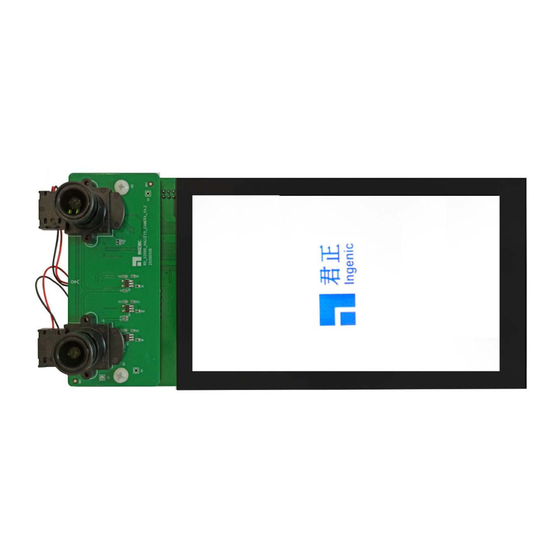
One DMIC board (optional) Figure 1-2 Halley5 Development Kit (with LCD/Camera board) The core board includes an Ingenic X2000 processor, an AMPAK AP6256 Wi-Fi/Bluetooth module, and a 256MBytes SPI NAND flash and some discrete components. It also provides various interfaces in form of plated half holes module to extend the external devices. -
Page 6: Functional Block Diagram
Overview 1.2 Functional Block Diagram The functional block diagram of the Halley5 development kit is shown as below: CAMERA Interface RGMII Interface USB Interface POWER IC GMAC1 USB_OTG USB_HOST 8/10/12-bit DVP CAMERA Board GC2155 DC-DCx4 LDOx1 2 x 2-lane MIPI... -
Page 7: Halley5 Core Board
2.2.1 Power Circuit The Power supply to the Halley5 core board is derived from the base board, which is sourced by a 5V DC power input. The core board carries a PMIC and 2 LDOs, and the PMIC contains 4 DC-DC buck converters as well as a LDO. - Page 8 VSS_38 VSS_39 1V2P AVDEFUSE VSS_40 EFUSE 0.1uF 0.1uF 0.1uF 0.1uF 10k/1% DDR_VREF 1V8P 0.1uF 10k/1% 1uF/NC WPM2031/NC 100k/NC EFUSE_N Figure 2-1 Halley5 Core Board Power Circuit X2000 Development Kit User Manual Copyright® 2005-2021 Ingenic Semiconductor Co., Ltd. All rights reserved.
-
Page 9: Wifi & Bt Function Circuit
Figure 2-2 Halley5 Core Board WI-FI & BT Circuit 2.2.3 SPI Flash Function Circuit The storage component on the Halley5 core board is 256MBytes SPI NAND Flash. And the hardware circuit and PCB layout are compatible with both SPI NOR flash. -
Page 10: Halley5 Base Board
3.2 Block Function Description of the Base Board 3.2.1 USB OTG function circuit The TYPE-C port J2 on the Halley5 base board is the download port as well ADB debug port. But if users cap JP1, J2 will be switched as a USB HOST interface automatically. -
Page 11: Debug Function Circuit
In order to facilitate users to debug, the base board is equipped with a USB to UART chip. Using generic USB cable to connect the J3 to PC, it will help to use the USB serial port on the PC directly. The default serial debug port of Halley5 is UART3_RXD and UART3_TXD of GPIO PC group. UART3_RXD... -
Page 12: Amic Function Circuit
MICLP 2.2K MICBIAS 0.1uF Figure 3-4 Halley5 Base Board AMIC Circuit 3.2.5 DMIC The base board has a DMIC port, and Halley5 is able to support AMIC and four-channel DMICs recording at the same time. 3V3P DMIC_IN0 DMIC_VDD DMIC_IN1 DMIC_CLK 0.1uF... -
Page 13: Keys Function Circuit
Halley5 boot from SPI NAND Flash by default. By pressing SW4, Halley5 can boot from SD card at MSC2@3.3V, and by pressing SW3, Halley5 can boot from USB (USB boot is to download code from PC). -
Page 14: Camera Interface
The base board supports 4-lane or 2 x 2-lane MIPI + DVP CAMERA interface (J7), which can be used to extend various cameras. Halley5 Development Kit provides a camera board which has two CMOS sensor OV 2735 ( image size 108 0P@30fps) by default. -
Page 15: Ethernet Interface
XTAL_OUT_1 2.4K/1% XTL_OUT RBIAS XTAL_IN_1 XTL_IN 3V3P LED_1000_1 200R Y T8511 XTAL_IN_1 22pF Y 125MHz XTAL_OUT_1 22pF RGMAC1_PHY _CLK Figure 3-11 Halley5 Base Board Ethernet Circuit X2000 Development Kit User Manual Copyright® 2005-2021 Ingenic Semiconductor Co., Ltd. All rights reserved. -
Page 16: Expansion Interface
PD18 AUX4 AUX0 AUX1 AUX2 AUX5 AUX3 PC07 PC05 3V3P 3V3P DC5V DC5V HEADER 12X2 0.1uF 10uF 0.1uF 10uF Figure 3-12 Halley5 Base Board Expansion Interface X2000 Development Kit User Manual Copyright® 2005-2021 Ingenic Semiconductor Co., Ltd. All rights reserved. -
Page 17: Quick Start The Halley5 Development Kit
SPI NAND Flash automatically. This will lead to start the preconfigured bootloader and Linux kernel. 4.3 Firmware Downloading Please use a USB cable connect the Halley5 base board to the PC through USB_DOWNLOAD port (J2), and X2000 Development Kit User Manual... - Page 18 X2000 will be under USB boot mode and start downloading firmware from PC through the USB port (J2). Then release the BOOT key SW3. Please find more detailed instructions for using the burning tool (USBCloner) from the USBCloner guide. X2000 Development Kit User Manual Copyright® 2005-2021 Ingenic Semiconductor Co., Ltd. All rights reserved.
Need help?
Do you have a question about the Halley5 and is the answer not in the manual?
Questions and answers