Table of Contents
Advertisement
Quick Links
WiMag Vehicle Detection System
AND HELD IN THE SIEMENS DOCUMENT CONTROL TOOL.
All PAPER COPIES ARE DEEMED UNCONTROLLED COPIES
Prepared By
Company/Dept.
Siemens Traffic Controls/Engineering
Name
Ore Oluwatudimu, Ashley Thorpe, K.W.P
Function
Product Engineer (Product Development)
Signature
Date
COPYRIGHT STATEMENT
The information contained herein is the property of Siemens Mobility Limited. And is supplied without
liability for errors or omissions. No part may be reproduced or used except as authorised by contract or
other written permission. The copyright and the foregoing restriction on reproduction and use extend to
all media in which the information may be embodied
Copyright © Siemens Mobility Limited 2012. All Rights Reserved.
Unrestricted
General Handbook
Part no.
667/HB/47200/000
THIS DOCUMENT IS ELECTRONICALLY APPROVED
Mobility, Traffic Solutions
Sopers Lane, Poole, Dorset
Checked and Released
Siemens Traffic Controls/ Engineering
Antonio Rhodes
Hardware Engineering Manager
BH17 7ER
Advertisement
Table of Contents

Related Manuals for Siemens 667/HB/47200/000


Summary of Contents for Siemens 667/HB/47200/000
- Page 1 Date COPYRIGHT STATEMENT The information contained herein is the property of Siemens Mobility Limited. And is supplied without liability for errors or omissions. No part may be reproduced or used except as authorised by contract or other written permission. The copyright and the foregoing restriction on reproduction and use extend to all media in which the information may be embodied Copyright ©...
- Page 2 Version Page 2 of 117 Status Issued Last Editor Jeerh, Manpreet Date March 2020 Document WIMAG GENERAL HANDBOOK Doc. No. 667/HB/47200/000 Name Copyright © Siemens Mobility Limited 2012. All Rights Reserved.
- Page 3 Version Page 3 of 117 Status Issued Last Editor Jeerh, Manpreet Date March 2020 Document WIMAG GENERAL HANDBOOK Doc. No. 667/HB/47200/000 Name Copyright © Siemens Mobility Limited 2012. All Rights Reserved.
- Page 4 Sopers Lane, Poole, Dorset BH17 7ER Product Advisory Notice : Sensys Version Page 4 of 117 Status Issued Last Editor Jeerh, Manpreet Date March 2020 Document WIMAG GENERAL HANDBOOK Doc. No. 667/HB/47200/000 Name Copyright © Siemens Mobility Limited 2012. All Rights Reserved.
- Page 5 There are no approved modifications for this product. Warning Use of components other than those indicated within this document or modifications or enhancements that have not been authorised by Siemens will invalidate Type Approval of this product. Version Page 5 of 117...
-
Page 6: Table Of Contents
Interface Card IP Addressing for Standard Interface Card /Loop Detector Replacement Interface Card ........................... 55 Version Page 6 of 117 Status Issued Last Editor Jeerh, Manpreet Date March 2020 Document WIMAG GENERAL HANDBOOK Doc. No. 667/HB/47200/000 Name Copyright © Siemens Mobility Limited 2012. All Rights Reserved. - Page 7 Disappearing Sensors right after commissioning ............87 16.2.3 Wireless performance ....................87 Version Page 7 of 117 Status Issued Last Editor Jeerh, Manpreet Date March 2020 Document WIMAG GENERAL HANDBOOK Doc. No. 667/HB/47200/000 Name Copyright © Siemens Mobility Limited 2012. All Rights Reserved.
- Page 8 Count for mixed bikes and pedestrians ..............114 Appendix C 4 Port PoE (Obsolete) .................115 Version Page 8 of 117 Status Issued Last Editor Jeerh, Manpreet Date March 2020 Document WIMAG GENERAL HANDBOOK Doc. No. 667/HB/47200/000 Name Copyright © Siemens Mobility Limited 2012. All Rights Reserved.
- Page 9 4 Port PoE Switch ....................116 C.3.2 Installation of rack ....................117 Version Page 9 of 117 Status Issued Last Editor Jeerh, Manpreet Date March 2020 Document WIMAG GENERAL HANDBOOK Doc. No. 667/HB/47200/000 Name Copyright © Siemens Mobility Limited 2012. All Rights Reserved.
- Page 10 Figure 52 : User Maintenance Ethernet Port ..................72 Version Page 10 of 117 Status Issued Last Editor Jeerh, Manpreet Date March 2020 Document WIMAG GENERAL HANDBOOK Doc. No. 667/HB/47200/000 Name Copyright © Siemens Mobility Limited 2012. All Rights Reserved.
- Page 11 Table 21 : The installation of a WiMag Detector ................96 Version Page 11 of 117 Status Issued Last Editor Jeerh, Manpreet Date March 2020 Document WIMAG GENERAL HANDBOOK Doc. No. 667/HB/47200/000 Name Copyright © Siemens Mobility Limited 2012. All Rights Reserved.
-
Page 12: Introduction
Open source software SCOOT Split, Cycle and Offset Optimization Technique Version Page 12 of 117 Status Issued Last Editor Jeerh, Manpreet Date March 2020 Document WIMAG GENERAL HANDBOOK Doc. No. 667/HB/47200/000 Name Copyright © Siemens Mobility Limited 2012. All Rights Reserved. -
Page 13: Issue History
TS009451 – Line powered repeater M. Jeerh installation instructions Version Page 13 of 117 Status Issued Last Editor Jeerh, Manpreet Date March 2020 Document WIMAG GENERAL HANDBOOK Doc. No. 667/HB/47200/000 Name Copyright © Siemens Mobility Limited 2012. All Rights Reserved. -
Page 14: System Overview
Figure 1 : Diagram of a typical Standard WiMag System Overview – Large Systems Version Page 14 of 117 Status Issued Last Editor Jeerh, Manpreet Date March 2020 Document WIMAG GENERAL HANDBOOK Doc. No. 667/HB/47200/000 Name Copyright © Siemens Mobility Limited 2012. All Rights Reserved. -
Page 15: Figure 2 : Diagram Of A Typical Standard Wimag System - Small System
CONTROLLER CABINET Figure 3 : WiMag FlexRack System Overview Version Page 15 of 117 Status Issued Last Editor Jeerh, Manpreet Date March 2020 Document WIMAG GENERAL HANDBOOK Doc. No. 667/HB/47200/000 Name Copyright © Siemens Mobility Limited 2012. All Rights Reserved. -
Page 16: Software Versions
‘visable’ to the user. Version Page 16 of 117 Status Issued Last Editor Jeerh, Manpreet Date March 2020 Document WIMAG GENERAL HANDBOOK Doc. No. 667/HB/47200/000 Name Copyright © Siemens Mobility Limited 2012. All Rights Reserved. -
Page 17: System Elements - Common Wimag Detection Equipment
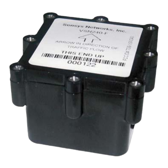
10 years. The sensors will continuously self-calibrate so that the earths magnetic fluctuations are always considered as part of the detection decision. The magnetometer sensor is manufactured by Sensys Networks Inc. Siemens supply the VSN240-F variant, which can be used for both road and stop-line applications. -
Page 18: Microradar™ Sensor
Figure 6 : MicroRadar™ installed in its clamshell for easy installation Version Page 18 of 117 Status Issued Last Editor Jeerh, Manpreet Date March 2020 Document WIMAG GENERAL HANDBOOK Doc. No. 667/HB/47200/000 Name Copyright © Siemens Mobility Limited 2012. All Rights Reserved. -
Page 19: Table 3 : Microradar Sensor Specifications
The battery is designed to have a life expectancy of at least 10 years. The magnetometer sensor is manufactured by Sensys Networks Inc. Siemens supply the VSN240-M variant, which can be used for both road and stop-line applications. -
Page 20: Flex-Ap Access Point
Table 5 : Access Point Specifications Note: It is highly recommended that Flex-AP-D-XCS is specified and used. This includes an internal load that will allow for proper operation with the Siemens WiMag Loop Replacement Card ( 667/1/47280/000 Full data sheet may be found on the Sensys website : http://www.sensysnetworks.com/... -
Page 21: Rp240-Bh Repeater
Full data sheet may be found on the Sensys website : http://www.sensysnetworks.com/ Version Page 21 of 117 Status Issued Last Editor Jeerh, Manpreet Date March 2020 Document WIMAG GENERAL HANDBOOK Doc. No. 667/HB/47200/000 Name Copyright © Siemens Mobility Limited 2012. All Rights Reserved. -
Page 22: Rp240-Bh Flex-Node
Operating Temp. -40ºC to +80ºC Figure 10 : Flex-Node Specifications Version Page 22 of 117 Status Issued Last Editor Jeerh, Manpreet Date March 2020 Document WIMAG GENERAL HANDBOOK Doc. No. 667/HB/47200/000 Name Copyright © Siemens Mobility Limited 2012. All Rights Reserved. -
Page 23: System Elements - Wimag Communications Rack Assemblies
Loop Detector Replacement card. Figure 11 : Standard WiMag Communications Rack Version Page 23 of 117 Status Issued Last Editor Jeerh, Manpreet Date March 2020 Document WIMAG GENERAL HANDBOOK Doc. No. 667/HB/47200/000 Name Copyright © Siemens Mobility Limited 2012. All Rights Reserved. -
Page 24: Figure 12 : Standard Wimag Communications Rack System Overview
Figure 12 : Standard WiMag Communications Rack System Overview Figure 13 : WiMag FlexRack – 2U Version Page 24 of 117 Status Issued Last Editor Jeerh, Manpreet Date March 2020 Document WIMAG GENERAL HANDBOOK Doc. No. 667/HB/47200/000 Name Copyright © Siemens Mobility Limited 2012. All Rights Reserved. -
Page 25: Figure 14 : Wimag Flexrack - 3U
The following sections outline the various system elements required for WiMag communications rack assemblies. Version Page 25 of 117 Status Issued Last Editor Jeerh, Manpreet Date March 2020 Document WIMAG GENERAL HANDBOOK Doc. No. 667/HB/47200/000 Name Copyright © Siemens Mobility Limited 2012. All Rights Reserved. -
Page 26: Four Port Poe Switch (Obsolete
(PD) has been connected prior to activating the power. Version Page 26 of 117 Status Issued Last Editor Jeerh, Manpreet Date March 2020 Document WIMAG GENERAL HANDBOOK Doc. No. 667/HB/47200/000 Name Copyright © Siemens Mobility Limited 2012. All Rights Reserved. -
Page 27: Spp And Flexcontrol (Ap)
-40ºC to +85ºC Detector Interface Ethernet to WiMag Interface card variants Version Page 27 of 117 Status Issued Last Editor Jeerh, Manpreet Date March 2020 Document WIMAG GENERAL HANDBOOK Doc. No. 667/HB/47200/000 Name Copyright © Siemens Mobility Limited 2012. All Rights Reserved. -
Page 28: Flexisolator
Designed for road side cabinet installation Operating Temp. -40ºC to +85ºC Version Page 28 of 117 Status Issued Last Editor Jeerh, Manpreet Date March 2020 Document WIMAG GENERAL HANDBOOK Doc. No. 667/HB/47200/000 Name Copyright © Siemens Mobility Limited 2012. All Rights Reserved. -
Page 29: The Standard Interface Card
Ethernet switches. Version Page 29 of 117 Status Issued Last Editor Jeerh, Manpreet Date March 2020 Document WIMAG GENERAL HANDBOOK Doc. No. 667/HB/47200/000 Name Copyright © Siemens Mobility Limited 2012. All Rights Reserved. -
Page 30: Controller Configuration
When using IC4 to generate a controller configuration, the recommendation is to select 24/0 as the card interface type. Version Page 30 of 117 Status Issued Last Editor Jeerh, Manpreet Date March 2020 Document WIMAG GENERAL HANDBOOK Doc. No. 667/HB/47200/000 Name Copyright © Siemens Mobility Limited 2012. All Rights Reserved. -
Page 31: Front Panel Description
1 x SW Run – Red : This in normally ‘ON’ when the card software is running. Version Page 31 of 117 Status Issued Last Editor Jeerh, Manpreet Date March 2020 Document WIMAG GENERAL HANDBOOK Doc. No. 667/HB/47200/000 Name Copyright © Siemens Mobility Limited 2012. All Rights Reserved. -
Page 32: System Elements - Wimag Loop Detector Replacement Card
(access point, repeater and sensor) and the traffic controller and may be used as a direct replacement for loop detector cards. Version Page 32 of 117 Status Issued Last Editor Jeerh, Manpreet Date March 2020 Document WIMAG GENERAL HANDBOOK Doc. No. 667/HB/47200/000 Name Copyright © Siemens Mobility Limited 2012. All Rights Reserved. -
Page 33: Figure 22 - Diagram Of A Typical Wimag System - Small System
WiMag is to be retrofitted into controllers in place of existing loop detectors. Version Page 33 of 117 Status Issued Last Editor Jeerh, Manpreet Date March 2020 Document WIMAG GENERAL HANDBOOK Doc. No. 667/HB/47200/000 Name Copyright © Siemens Mobility Limited 2012. All Rights Reserved. -
Page 34: Front Panel Description
Note : During a board reset, all of the front panel LEDs will illuminate briefly to indicate that a reset has been performed. Version Page 34 of 117 Status Issued Last Editor Jeerh, Manpreet Date March 2020 Document WIMAG GENERAL HANDBOOK Doc. No. 667/HB/47200/000 Name Copyright © Siemens Mobility Limited 2012. All Rights Reserved. -
Page 35: Status Leds Indications
Will illuminate when there is a supply failure e.g. supply drops below 12V. Version Page 35 of 117 Status Issued Last Editor Jeerh, Manpreet Date March 2020 Document WIMAG GENERAL HANDBOOK Doc. No. 667/HB/47200/000 Name Copyright © Siemens Mobility Limited 2012. All Rights Reserved. -
Page 36: Poe Port Indications
The Serial Interface Port is for Engineering diagnostic use only. Version Page 36 of 117 Status Issued Last Editor Jeerh, Manpreet Date March 2020 Document WIMAG GENERAL HANDBOOK Doc. No. 667/HB/47200/000 Name Copyright © Siemens Mobility Limited 2012. All Rights Reserved. -
Page 37: System Design Methodology
However, the Sensys Networks design guides are generalised. This section outlines specific design elements that are required for a successful implementation using Siemens interface card and controller. In addition, Siemens have carried out extensive testing and therefore there are several default settings that are applied when using the WiMag access points in Siemens installations. -
Page 38: Design Guidelines For Access Points
The reader is now referred to ‘System Design Guide’ for IPS and WiMag (667/HB/47200/001). Assumes VSN240-F-2 or VSN240-F-GR As above Version Page 38 of 117 Status Issued Last Editor Jeerh, Manpreet Date March 2020 Document WIMAG GENERAL HANDBOOK Doc. No. 667/HB/47200/000 Name Copyright © Siemens Mobility Limited 2012. All Rights Reserved. -
Page 39: Design Guidelines (Other Equipment)
3. Sensors from one access point need not terminate on the same interface card. Version Page 39 of 117 Status Issued Last Editor Jeerh, Manpreet Date March 2020 Document WIMAG GENERAL HANDBOOK Doc. No. 667/HB/47200/000 Name Copyright © Siemens Mobility Limited 2012. All Rights Reserved. -
Page 40: System Configuration
Table 7 : Interface Card Configuration and User Guide Version Page 40 of 117 Status Issued Last Editor Jeerh, Manpreet Date March 2020 Document WIMAG GENERAL HANDBOOK Doc. No. 667/HB/47200/000 Name Copyright © Siemens Mobility Limited 2012. All Rights Reserved. -
Page 41: Standard Interface Card : Configuration
27, it may be necessary to remove the cards front panel to gain access to this link. Version Page 41 of 117 Status Issued Last Editor Jeerh, Manpreet Date March 2020 Document WIMAG GENERAL HANDBOOK Doc. No. 667/HB/47200/000 Name Copyright © Siemens Mobility Limited 2012. All Rights Reserved. -
Page 42: Figure 27 : Standard Interface Card Configuration Link
Version Page 42 of 117 Status Issued Last Editor Jeerh, Manpreet Date March 2020 Document WIMAG GENERAL HANDBOOK Doc. No. 667/HB/47200/000 Name Copyright © Siemens Mobility Limited 2012. All Rights Reserved. -
Page 43: Figure 29 : Apply Settings Screen
Figure 30 : Backplane Address Switch and Address Link Version Page 43 of 117 Status Issued Last Editor Jeerh, Manpreet Date March 2020 Document WIMAG GENERAL HANDBOOK Doc. No. 667/HB/47200/000 Name Copyright © Siemens Mobility Limited 2012. All Rights Reserved. -
Page 44: Wimag Loop Detector Replacement Card : Configuration
Replacement Card. Figure 31 : WiMag Loop Detector Replacement Card Version Page 44 of 117 Status Issued Last Editor Jeerh, Manpreet Date March 2020 Document WIMAG GENERAL HANDBOOK Doc. No. 667/HB/47200/000 Name Copyright © Siemens Mobility Limited 2012. All Rights Reserved. -
Page 45: Figure 32 : Loop Detector Replacement Card Configuration Link
However, it is generally recommended that username and password are kept blank. Version Page 45 of 117 Status Issued Last Editor Jeerh, Manpreet Date March 2020 Document WIMAG GENERAL HANDBOOK Doc. No. 667/HB/47200/000 Name Copyright © Siemens Mobility Limited 2012. All Rights Reserved. -
Page 46: Figure 33 : General Settings Screen
11. Pull the interface card from the rack 12. Re-apply the ‘configuration link if removed. Version Page 46 of 117 Status Issued Last Editor Jeerh, Manpreet Date March 2020 Document WIMAG GENERAL HANDBOOK Doc. No. 667/HB/47200/000 Name Copyright © Siemens Mobility Limited 2012. All Rights Reserved. -
Page 47: Configuring Access Points, Repeaters And Sensors
‘Traffic Dot Set Up and Operating Guide’ for detail instructions on operating the Traffic Dot application and configuration of the access point, repeater and sensors. This section outlines specific settings that Siemens require, in order to operate the WiMag vehicle detection system in an optimal manner. -
Page 48: Initial Connection
Cmds tab of the Sensor Config Window. Channels should be set as specified within the junction configuration spreadsheet. Version Page 48 of 117 Status Issued Last Editor Jeerh, Manpreet Date March 2020 Document WIMAG GENERAL HANDBOOK Doc. No. 667/HB/47200/000 Name Copyright © Siemens Mobility Limited 2012. All Rights Reserved. -
Page 49: Table 9 : Sensor Configuration Settings
20 outputs the sensor appears on. Version Page 49 of 117 Status Issued Last Editor Jeerh, Manpreet Date March 2020 Document WIMAG GENERAL HANDBOOK Doc. No. 667/HB/47200/000 Name Copyright © Siemens Mobility Limited 2012. All Rights Reserved. -
Page 50: Bicycle Sensor Configuration
The Traffic Dot interface will also allow for the two detections types to be routed to differing outputs on a WiMag card. For details on how to configure the settings please refer to Section 7.3.7, for Siemens specific settings, in combination with the Traffic Dot Set Up and Operating Guide (P/N 152-240-001-071). -
Page 51: Figure 36 : Microradar Command To Sensor Window
Refer to Appendix B for use case specific information on bike sensor installation and configuration. Version Page 51 of 117 Status Issued Last Editor Jeerh, Manpreet Date March 2020 Document WIMAG GENERAL HANDBOOK Doc. No. 667/HB/47200/000 Name Copyright © Siemens Mobility Limited 2012. All Rights Reserved. -
Page 52: Final Access Point Configuration
This value should be set to 0.125s if tandem repeaters are to be used. This is a restriction of the system. Version Page 52 of 117 Status Issued Last Editor Jeerh, Manpreet Date March 2020 Document WIMAG GENERAL HANDBOOK Doc. No. 667/HB/47200/000 Name Copyright © Siemens Mobility Limited 2012. All Rights Reserved. -
Page 53: Figure 39 : Recalibrate Timeout Setting
Advanced tab. The junction colour code should then be copied from the configuration spreadsheet into the AP Colour Code field. 7. Siemens protocol must be switched on within the access point to ensure correct communications with the standard interface card. Open the System Config - Other tab in the Access point Config Window and click Custom Application Settings, then check the STS Enable box to switch Siemens protocol on. -
Page 54: Configuration For Scoot Systems
3. Add a values of 100 in the field titled ‘Extension (millisecs):’. Version Page 54 of 117 Status Issued Last Editor Jeerh, Manpreet Date March 2020 Document WIMAG GENERAL HANDBOOK Doc. No. 667/HB/47200/000 Name Copyright © Siemens Mobility Limited 2012. All Rights Reserved. -
Page 55: Interface Card Ip Addressing For Standard Interface Card /Loop Detector Replacement Interface Card
Figure 42 : AP System Configuration 1. The Siemens protocol must be switched on within the access point to ensure correct communications with the standard interface card. Open the System Config - Other... -
Page 56: Interface Card Ip Addressing For Standard Interface Card /Loop Detector Replacement Interface Card - Bike Detectors
BH17 7ER tab in the Access point Config Window and click Custom Application Settings, then check the STS Enable box to switch Siemens protocol on. 2. Select the sensor within TrafficDot, that you want to route to a standard interface card - open the Sensor Config Window. -
Page 57: Configuration Files
In order to ensure a speedy recovery, after an unlikely failure, the configuration file for each access point should be downloaded and stored for future use. Note: For Siemens installations and maintenance contracts it is recommended that the configuration file is stored on the ‘TIE Server’. -
Page 58: Figure 43 : Configuration Download - Command Tab
8. Select ‘Reboot’ to reboot the access point. The access point will then recover with the pre-defined configuration. Version Page 58 of 117 Status Issued Last Editor Jeerh, Manpreet Date March 2020 Document WIMAG GENERAL HANDBOOK Doc. No. 667/HB/47200/000 Name Copyright © Siemens Mobility Limited 2012. All Rights Reserved. -
Page 59: General Installation Instructions
5. Install WiMag Communications Rack or WiMag Loop Detector Replacement Card as required. Version Page 59 of 117 Status Issued Last Editor Jeerh, Manpreet Date March 2020 Document WIMAG GENERAL HANDBOOK Doc. No. 667/HB/47200/000 Name Copyright © Siemens Mobility Limited 2012. All Rights Reserved. -
Page 60: Installation Of Wimag Sensors
The instructions for the installation of the magnetometer/MicroRadar sensors are covered in a separate document, 667/CC/47200/000 (METHOD STATEMENT). Version Page 60 of 117 Status Issued Last Editor Jeerh, Manpreet Date March 2020 Document WIMAG GENERAL HANDBOOK Doc. No. 667/HB/47200/000 Name Copyright © Siemens Mobility Limited 2012. All Rights Reserved. -
Page 61: Installation Of The Access Point (Ap240/Flexap) And Spp Radio
Figure 44 : Mounting Ball and Double Socket Arm 5m is the preferred minimum Version Page 61 of 117 Status Issued Last Editor Jeerh, Manpreet Date March 2020 Document WIMAG GENERAL HANDBOOK Doc. No. 667/HB/47200/000 Name Copyright © Siemens Mobility Limited 2012. All Rights Reserved. -
Page 62: Mounting The Access Point
6. Orientate the AP in the direction depicted, within the junction/installation drawing, and tighten the double socket arm to secure. Version Page 62 of 117 Status Issued Last Editor Jeerh, Manpreet Date March 2020 Document WIMAG GENERAL HANDBOOK Doc. No. 667/HB/47200/000 Name Copyright © Siemens Mobility Limited 2012. All Rights Reserved. -
Page 63: Pole Mounting Kit
10.2 Pole Mounting Kit Refer to section 11.1, below, for details. Version Page 63 of 117 Status Issued Last Editor Jeerh, Manpreet Date March 2020 Document WIMAG GENERAL HANDBOOK Doc. No. 667/HB/47200/000 Name Copyright © Siemens Mobility Limited 2012. All Rights Reserved. -
Page 64: Extension Pole Installation
Detector Replacement Card. This information is covered in sections 12, 13 and 14. Version Page 64 of 117 Status Issued Last Editor Jeerh, Manpreet Date March 2020 Document WIMAG GENERAL HANDBOOK Doc. No. 667/HB/47200/000 Name Copyright © Siemens Mobility Limited 2012. All Rights Reserved. -
Page 65: Installation Of The Repeater And Flexnode
Figure 48 : Square Plate and Clamping Band Version Page 65 of 117 Status Issued Last Editor Jeerh, Manpreet Date March 2020 Document WIMAG GENERAL HANDBOOK Doc. No. 667/HB/47200/000 Name Copyright © Siemens Mobility Limited 2012. All Rights Reserved. -
Page 66: Mounting Procedure
10.1 and 10.1.1 above. Version Page 66 of 117 Status Issued Last Editor Jeerh, Manpreet Date March 2020 Document WIMAG GENERAL HANDBOOK Doc. No. 667/HB/47200/000 Name Copyright © Siemens Mobility Limited 2012. All Rights Reserved. -
Page 67: Flexnode Repeater (Aka Line Power Repeater) Power Connection
3. Drill a 20 mm hole using the rear dimple on the side of the aspect box and fit the supplied M20 cable gland. Version Page 67 of 117 Status Issued Last Editor Jeerh, Manpreet Date March 2020 Document WIMAG GENERAL HANDBOOK Doc. No. 667/HB/47200/000 Name Copyright © Siemens Mobility Limited 2012. All Rights Reserved. - Page 68 Coil up any excess cable. Version Page 68 of 117 Status Issued Last Editor Jeerh, Manpreet Date March 2020 Document WIMAG GENERAL HANDBOOK Doc. No. 667/HB/47200/000 Name Copyright © Siemens Mobility Limited 2012. All Rights Reserved.
-
Page 69: Cable Installation
4x the cable diameter (50mm) should be observed. Note: To maintain product safety, the armoured part of the cable must be terminated at the controller end. For Siemens controllers the GB7:4/MC702 CET Gland kit is used. 1. Access points connect to the WiMag rack assembly via an Ethernet cable. This cable should be standard Ethernet compatible, outdoor rated, 4-pair CAT5 (or better). -
Page 70: Figure 50 : Termination Of Armoured Cable To Cet Bar
CAT5e Cable Table 13 : RJ45 Interface Cable Connection Version Page 70 of 117 Status Issued Last Editor Jeerh, Manpreet Date March 2020 Document WIMAG GENERAL HANDBOOK Doc. No. 667/HB/47200/000 Name Copyright © Siemens Mobility Limited 2012. All Rights Reserved. -
Page 71: Installation Of The Wimag Communications Rack
Figure 51 : 8 Port PoE Device showing two free non-PoE ports (numbered 1 and 2) Version Page 71 of 117 Status Issued Last Editor Jeerh, Manpreet Date March 2020 Document WIMAG GENERAL HANDBOOK Doc. No. 667/HB/47200/000 Name Copyright © Siemens Mobility Limited 2012. All Rights Reserved. -
Page 72: Figure 52 : User Maintenance Ethernet Port
BH17 7ER Figure 52 : User Maintenance Ethernet Port Version Page 72 of 117 Status Issued Last Editor Jeerh, Manpreet Date March 2020 Document WIMAG GENERAL HANDBOOK Doc. No. 667/HB/47200/000 Name Copyright © Siemens Mobility Limited 2012. All Rights Reserved. -
Page 73: Port Poe Switch (Obsolete)
Figure 53 : Eight Port PoE Switch (DC Connection) Version Page 73 of 117 Status Issued Last Editor Jeerh, Manpreet Date March 2020 Document WIMAG GENERAL HANDBOOK Doc. No. 667/HB/47200/000 Name Copyright © Siemens Mobility Limited 2012. All Rights Reserved. -
Page 74: Mounting The Wimag Rack Assembly
This assembly has been modified and is included with the rack. Version Page 74 of 117 Status Issued Last Editor Jeerh, Manpreet Date March 2020 Document WIMAG GENERAL HANDBOOK Doc. No. 667/HB/47200/000 Name Copyright © Siemens Mobility Limited 2012. All Rights Reserved. -
Page 75: Backplane Connection
In future versions the interface to the controller will be serial and will be via this interconnect. Version Page 75 of 117 Status Issued Last Editor Jeerh, Manpreet Date March 2020 Document WIMAG GENERAL HANDBOOK Doc. No. 667/HB/47200/000 Name Copyright © Siemens Mobility Limited 2012. All Rights Reserved. -
Page 76: Backplane Addressing
Figure 57 : Backplane Address Switch and Address Link Version Page 76 of 117 Status Issued Last Editor Jeerh, Manpreet Date March 2020 Document WIMAG GENERAL HANDBOOK Doc. No. 667/HB/47200/000 Name Copyright © Siemens Mobility Limited 2012. All Rights Reserved. -
Page 77: Main Supply Connection
Figure 58 : Mains Connection for 48V DC PSU Version Page 77 of 117 Status Issued Last Editor Jeerh, Manpreet Date March 2020 Document WIMAG GENERAL HANDBOOK Doc. No. 667/HB/47200/000 Name Copyright © Siemens Mobility Limited 2012. All Rights Reserved. -
Page 78: Figure 59 : Mains Connection For 24V Dc Psu (Left: /200 Variant; Right: /300 Variant)
DO NOT cable the WiMag rack assembly unit while the controller cabinet is live. Version Page 78 of 117 Status Issued Last Editor Jeerh, Manpreet Date March 2020 Document WIMAG GENERAL HANDBOOK Doc. No. 667/HB/47200/000 Name Copyright © Siemens Mobility Limited 2012. All Rights Reserved. -
Page 79: Connecting A Wimag Access Point
3. Connect the link cable between the two backplanes. Version Page 79 of 117 Status Issued Last Editor Jeerh, Manpreet Date March 2020 Document WIMAG GENERAL HANDBOOK Doc. No. 667/HB/47200/000 Name Copyright © Siemens Mobility Limited 2012. All Rights Reserved. -
Page 80: Figure 61 : Additional Backplane
5. Connect the interface card to a spare Ethernet port within the communications rack. Figure 62 : Additional Interface Card Version Page 80 of 117 Status Issued Last Editor Jeerh, Manpreet Date March 2020 Document WIMAG GENERAL HANDBOOK Doc. No. 667/HB/47200/000 Name Copyright © Siemens Mobility Limited 2012. All Rights Reserved. -
Page 81: Installation Of The Loop Detector Replacement Cards
Replacement Card, care should be taken to ensure that the detector power supply capacity is not exceeded. Version Page 81 of 117 Status Issued Last Editor Jeerh, Manpreet Date March 2020 Document WIMAG GENERAL HANDBOOK Doc. No. 667/HB/47200/000 Name Copyright © Siemens Mobility Limited 2012. All Rights Reserved. -
Page 82: Connecting A Wimag Access Point
Siemens Mobility Limited Sopers Lane, Poole, Dorset BH17 7ER For Siemens Traffic Controllers, a detector supply transformer would be considered the correct supply source. 14.3 Connecting a WiMag Access Point Access points are the only system elements installed outside the controller cabinet that require cabling. -
Page 83: Figure 64 : Additional Card Linking
Linking cables can be supplied as required; 998/4/88351/002 CABLE PATCH CAT5e RJ45 FTP 0.2m GREY Version Page 83 of 117 Status Issued Last Editor Jeerh, Manpreet Date March 2020 Document WIMAG GENERAL HANDBOOK Doc. No. 667/HB/47200/000 Name Copyright © Siemens Mobility Limited 2012. All Rights Reserved. -
Page 84: Commissioning
2. Select the ‘Board Test’ page on the web interface Version Page 84 of 117 Status Issued Last Editor Jeerh, Manpreet Date March 2020 Document WIMAG GENERAL HANDBOOK Doc. No. 667/HB/47200/000 Name Copyright © Siemens Mobility Limited 2012. All Rights Reserved. -
Page 85: Controller Commissioning
The reader is to refer to the appropriate ‘controller handbook’ for details. Version Page 85 of 117 Status Issued Last Editor Jeerh, Manpreet Date March 2020 Document WIMAG GENERAL HANDBOOK Doc. No. 667/HB/47200/000 Name Copyright © Siemens Mobility Limited 2012. All Rights Reserved. -
Page 86: Maintenance (Fault Finding)
5. Send sensor ID to Sensys Networks to check for potential issues Version Page 86 of 117 Status Issued Last Editor Jeerh, Manpreet Date March 2020 Document WIMAG GENERAL HANDBOOK Doc. No. 667/HB/47200/000 Name Copyright © Siemens Mobility Limited 2012. All Rights Reserved. -
Page 87: Disappearing Sensors Right After Commissioning
Version Page 87 of 117 Status Issued Last Editor Jeerh, Manpreet Date March 2020 Document WIMAG GENERAL HANDBOOK Doc. No. 667/HB/47200/000 Name Copyright © Siemens Mobility Limited 2012. All Rights Reserved. -
Page 88: Occasional Sticking Sensors
Version Page 88 of 117 Status Issued Last Editor Jeerh, Manpreet Date March 2020 Document WIMAG GENERAL HANDBOOK Doc. No. 667/HB/47200/000 Name Copyright © Siemens Mobility Limited 2012. All Rights Reserved. -
Page 89: Figure 67 : Example Of Normal Performance Observed Using 'D' Mode
Figure 68 : Example of Magnetic Interference Observed using 'D' Mode Version Page 89 of 117 Status Issued Last Editor Jeerh, Manpreet Date March 2020 Document WIMAG GENERAL HANDBOOK Doc. No. 667/HB/47200/000 Name Copyright © Siemens Mobility Limited 2012. All Rights Reserved. -
Page 90: Repeaters
3. Insufficiently charged battery - LEDs flash red and green consistently or not flash at all Version Page 90 of 117 Status Issued Last Editor Jeerh, Manpreet Date March 2020 Document WIMAG GENERAL HANDBOOK Doc. No. 667/HB/47200/000 Name Copyright © Siemens Mobility Limited 2012. All Rights Reserved. -
Page 91: Standard And Detector Replacement Interface Cards
3. The interface card itself is in fault mode. Version Page 91 of 117 Status Issued Last Editor Jeerh, Manpreet Date March 2020 Document WIMAG GENERAL HANDBOOK Doc. No. 667/HB/47200/000 Name Copyright © Siemens Mobility Limited 2012. All Rights Reserved. -
Page 92: Maintenance (Replacement And Repair)
8. On completion of the settings – click on the ‘Apply Settings’ and allow the unit to reboot. Version Page 92 of 117 Status Issued Last Editor Jeerh, Manpreet Date March 2020 Document WIMAG GENERAL HANDBOOK Doc. No. 667/HB/47200/000 Name Copyright © Siemens Mobility Limited 2012. All Rights Reserved. -
Page 93: Poe Switch Replacement
DIN rail. 5. Replacement is the reverse of removal. Version Page 93 of 117 Status Issued Last Editor Jeerh, Manpreet Date March 2020 Document WIMAG GENERAL HANDBOOK Doc. No. 667/HB/47200/000 Name Copyright © Siemens Mobility Limited 2012. All Rights Reserved. -
Page 94: Psu Replacement
This dependant on the transmit interval, which is set as 0.0625s as default. Other values are available. Version Page 94 of 117 Status Issued Last Editor Jeerh, Manpreet Date March 2020 Document WIMAG GENERAL HANDBOOK Doc. No. 667/HB/47200/000 Name Copyright © Siemens Mobility Limited 2012. All Rights Reserved. -
Page 95: Repeater Battery Replacement
Table 19 : Quick Start Guide for a Repeater Version Page 95 of 117 Status Issued Last Editor Jeerh, Manpreet Date March 2020 Document WIMAG GENERAL HANDBOOK Doc. No. 667/HB/47200/000 Name Copyright © Siemens Mobility Limited 2012. All Rights Reserved. -
Page 96: Sensor Replacement
Any queries should be directed to the Service Logistics Manager on (01530) 258181 Version Page 96 of 117 Status Issued Last Editor Jeerh, Manpreet Date March 2020 Document WIMAG GENERAL HANDBOOK Doc. No. 667/HB/47200/000 Name Copyright © Siemens Mobility Limited 2012. All Rights Reserved. -
Page 97: Disposal
All Traffic Solutions, Siemens depots operates an Environmental Management System (EMS). In accordance with its Environmental Policy Siemens applies the Waste Hierarchy when managing waste, segregating waste into a number of waste streams to optimise the re-use/recycling carried out by the approved waste contractors that take the waste away. -
Page 98: Part Numbers / Spares List
WiMag Standard Interface Card BACKPLANE 667/1/27121/000 ST800/700 OTU Supply Kit (Aux MCB) Version Page 98 of 117 Status Issued Last Editor Jeerh, Manpreet Date March 2020 Document WIMAG GENERAL HANDBOOK Doc. No. 667/HB/47200/000 Name Copyright © Siemens Mobility Limited 2012. All Rights Reserved. -
Page 99: Wimag Flexrack Equipment Spares
CABLE PATCH CAT5e RJ45 FTP 0.2m GREY 667/1/17205/000 Standard Backplane Version Page 99 of 117 Status Issued Last Editor Jeerh, Manpreet Date March 2020 Document WIMAG GENERAL HANDBOOK Doc. No. 667/HB/47200/000 Name Copyright © Siemens Mobility Limited 2012. All Rights Reserved. -
Page 100: Wimag On Street Spares
Sensor Clam Shell (for replacement) No clamshell required As above Version Page 100 of 117 Status Issued Last Editor Jeerh, Manpreet Date March 2020 Document WIMAG GENERAL HANDBOOK Doc. No. 667/HB/47200/000 Name Copyright © Siemens Mobility Limited 2012. All Rights Reserved. -
Page 101: Wimag Bracket Assemblies
667/1/33075/000 Nominal 160 VA, (6.6amps) – ELV Controller 667/1/33074/000 Version Page 101 of 117 Status Issued Last Editor Jeerh, Manpreet Date March 2020 Document WIMAG GENERAL HANDBOOK Doc. No. 667/HB/47200/000 Name Copyright © Siemens Mobility Limited 2012. All Rights Reserved. -
Page 102: Open Source Software
GNU General Public License, the GNU Lesser General Public License, the modified BSD license and the MIT license. In the event of conflicts between Siemens license conditions and the Open Source Software license conditions, the Open Source Software conditions shall prevail with respect to the Open Source Software portions of the software. - Page 103 We choose to use the JQuery Open Source software under the terms of the MIT License 1 Copyright (c) 2009 John Resig, http://jquery.com/ Version Page 103 of 117 Status Issued Last Editor Jeerh, Manpreet Date March 2020 Document WIMAG GENERAL HANDBOOK Doc. No. 667/HB/47200/000 Name Copyright © Siemens Mobility Limited 2012. All Rights Reserved.
- Page 104 Pietje Bel Pietje Bel SYNERGETICNeal Horman see: - Backplane Connections Version Page 104 of 117 Status Issued Last Editor Jeerh, Manpreet Date March 2020 Document WIMAG GENERAL HANDBOOK Doc. No. 667/HB/47200/000 Name Copyright © Siemens Mobility Limited 2012. All Rights Reserved.
-
Page 105: Appendix A - Backplane Connections
Figure A-1 : Standard Backplane Connections (for WiMag Loop Detector Replacement Card) Version Page 105 of 117 Status Issued Last Editor Jeerh, Manpreet Date March 2020 Document WIMAG GENERAL HANDBOOK Doc. No. 667/HB/47200/000 Name Copyright © Siemens Mobility Limited 2012. All Rights Reserved. -
Page 106: Appendix B - Bicycle Sensor User Cases
Use Motion – Not Set • Latch Car Subchannel – Not Set Version Page 106 of 117 Status Issued Last Editor Jeerh, Manpreet Date March 2020 Document WIMAG GENERAL HANDBOOK Doc. No. 667/HB/47200/000 Name Copyright © Siemens Mobility Limited 2012. All Rights Reserved. -
Page 107: Va Detection
‘Use Motion’ setting enabled, as well the sample rate being set to 4Hz. • Sample Rate – 4Hz Version Page 107 of 117 Status Issued Last Editor Jeerh, Manpreet Date March 2020 Document WIMAG GENERAL HANDBOOK Doc. No. 667/HB/47200/000 Name Copyright © Siemens Mobility Limited 2012. All Rights Reserved. -
Page 108: Count
Note: Multiple bikes that cross the detection zone simultaneously will be counted as a single bike. Version Page 108 of 117 Status Issued Last Editor Jeerh, Manpreet Date March 2020 Document WIMAG GENERAL HANDBOOK Doc. No. 667/HB/47200/000 Name Copyright © Siemens Mobility Limited 2012. All Rights Reserved. -
Page 109: Mixed Traffic : Bicycles And Vehicles
Figure 73 : Stopline sensor installation for mixed traffic Version Page 109 of 117 Status Issued Last Editor Jeerh, Manpreet Date March 2020 Document WIMAG GENERAL HANDBOOK Doc. No. 667/HB/47200/000 Name Copyright © Siemens Mobility Limited 2012. All Rights Reserved. -
Page 110: Figure 74 : Forward Reservation Area For Stopline Bike Sensors
Figure 74 : Forward reservation area for Stopline bike sensors. Version Page 110 of 117 Status Issued Last Editor Jeerh, Manpreet Date March 2020 Document WIMAG GENERAL HANDBOOK Doc. No. 667/HB/47200/000 Name Copyright © Siemens Mobility Limited 2012. All Rights Reserved. -
Page 111: Va Detection For Mixed Traffic
Note: Multiple bikes that cross the virtual detection zone simultaneously will be counted as a single bike. Version Page 111 of 117 Status Issued Last Editor Jeerh, Manpreet Date March 2020 Document WIMAG GENERAL HANDBOOK Doc. No. 667/HB/47200/000 Name Copyright © Siemens Mobility Limited 2012. All Rights Reserved. -
Page 112: Count Detection Mixed Traffic
Figure 76 : Installation and Configuration for Mixed Bike and Pedestrian Traffic - Stopline Version Page 112 of 117 Status Issued Last Editor Jeerh, Manpreet Date March 2020 Document WIMAG GENERAL HANDBOOK Doc. No. 667/HB/47200/000 Name Copyright © Siemens Mobility Limited 2012. All Rights Reserved. -
Page 113: Va Detection For Mixed Bikes And Pedestrians
Figure 77 : Installation and Configuration for Mixed Bike and Pedestrian Traffic - VA Version Page 113 of 117 Status Issued Last Editor Jeerh, Manpreet Date March 2020 Document WIMAG GENERAL HANDBOOK Doc. No. 667/HB/47200/000 Name Copyright © Siemens Mobility Limited 2012. All Rights Reserved. -
Page 114: Count For Mixed Bikes And Pedestrians
Note: Multiple bikes that cross the virtual detection zone simultaneously will be counted as a single bike. Version Page 114 of 117 Status Issued Last Editor Jeerh, Manpreet Date March 2020 Document WIMAG GENERAL HANDBOOK Doc. No. 667/HB/47200/000 Name Copyright © Siemens Mobility Limited 2012. All Rights Reserved. -
Page 115: Appendix C 4 Port Poe (Obsolete)
Each port will detect if an appropriate powered device (PD) has been connected prior to activating the power. Version Page 115 of 117 Status Issued Last Editor Jeerh, Manpreet Date March 2020 Document WIMAG GENERAL HANDBOOK Doc. No. 667/HB/47200/000 Name Copyright © Siemens Mobility Limited 2012. All Rights Reserved. -
Page 116: Installation Of Poe (13.1)
Figure 43 : 4 Port PoE Switch (48V DC Connection) Version Page 116 of 117 Status Issued Last Editor Jeerh, Manpreet Date March 2020 Document WIMAG GENERAL HANDBOOK Doc. No. 667/HB/47200/000 Name Copyright © Siemens Mobility Limited 2012. All Rights Reserved. -
Page 117: Installation Of Rack
Figure 50 : 4 Port PoE Device showing four free PoE ports (numbered 1 to 4) Version Page 117 of 117 Status Issued Last Editor Jeerh, Manpreet Date March 2020 Document WIMAG GENERAL HANDBOOK Doc. No. 667/HB/47200/000 Name Copyright © Siemens Mobility Limited 2012. All Rights Reserved.