Table of Contents
Advertisement
Quick Links
®
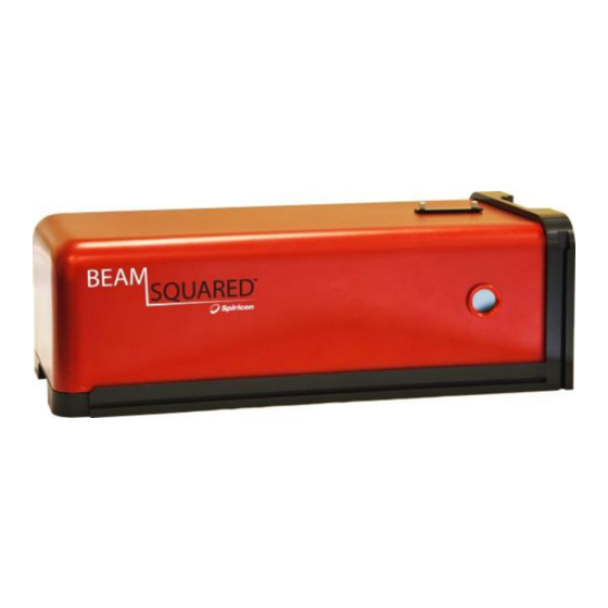
BeamSquared
User Guide
Beam Propagation Analyzer
®
®
For Windows 7
and Window 10
64 BIT
For Sales, Service or Technical Support
Phone: (435) 753-3729
Fax: (435) 753-5231
Service Email
service@us.ophiropt.com
Sales Email
sales@us.ophiropt.com
Ophir-Spiricon, LLC
3050 North 300 West
North Logan, Utah 84341
©2019 Ophir-Spiricon, LLC
Advertisement
Table of Contents

Related Manuals for OPHIR BeamSquared


Summary of Contents for OPHIR BeamSquared
- Page 1 ® For Windows 7 and Window 10 64 BIT For Sales, Service or Technical Support Phone: (435) 753-3729 Fax: (435) 753-5231 Service Email service@us.ophiropt.com Sales Email sales@us.ophiropt.com Ophir-Spiricon, LLC 3050 North 300 West North Logan, Utah 84341 ©2019 Ophir-Spiricon, LLC...
- Page 2 Thank you for your recent purchase of the BeamSquared system. At Ophir-Spiricon we strive to provide the highest level of leading edge photonic measurement technology and service possible. We hope that your experience with us is a pleasant one, and anticipate the relationship we build will serve your photonic measurement needs for years to come.
-
Page 3: How To Use This Guide
How to Use this Guide It is recommended that users review this guide before setting up and using the BeamSquared system. This guide will assist users in becoming familiar with the M measurement theory as well as acquire a basic understanding of the BeamSquared operation. - Page 4 Indicates warning information. Failure to follow instruction may result in harm to the user or product damage. Indicates that the instruction refers to operating BeamSquared in Manual Mode.
-
Page 5: Table Of Contents
BeamSquared Optical Train Dimensions ..................15 Software Information ........................ 16 Chapter 2 Setup ..........................17 Equipment ..........................17 BeamSquared Software Installation .................... 17 Prepare the BeamSquared for Operation ..................18 2.3.1 Mount the Optical Train ...................... 18 2.3.2 Install the Camera ......................19 2.3.3 Connect BeamSquared ....................... - Page 6 2.5.4 Beam Axial Alignment ......................28 Step Size and Start/Stop Selection ..................... 29 Chapter 3 Operating Controls and User Interface ................. 30 User Interface .......................... 30 3.1.1 Title Bar ..........................30 3.1.2 Ribbon Tab ........................31 3.1.3 Ribbon Bar ........................31 3.1.4 Panels ..........................
- Page 7 Four-Cuts on Two Axes ....................56 4.1.4 Step Table ......................... 57 4.1.5 Real Time M Mode ......................57 BeamSquared Operation ......................58 4.2.1 Configuration Wizard ......................58 4.2.2 Step by Step Wizard ......................62 Data Collection in Auto Mode ..................... 65 Useful Operations and Functions ....................
- Page 8 Astigmatism and Asymmetry ....................83 6.1.5 Focal Length Calculation ..................... 83 6.1.6 Path Length Calibration Values .................... 84 6.1.6.1 Z Lens ........................... 85 6.1.6.2 Z Fixture ........................85 6.1.6.3 Z Camera ........................85 6.1.7 BeamSquared Distance ....................... 86 Chapter 7 Troubleshooting ......................... 88...
- Page 9 Appendix A Lens Calibration Adjustments .................... 102 Plano convex Lens Calibration ....................102 Refractive Index of Common Lens Materials ................103 Appendix B Warranty ......................... 104 Appendix C BeamSquared Supported Cameras ..................105 Appendix D Camera Information ...................... 106 SP300 ............................ 106 D.1.1...
-
Page 11: Chapter 1 General Information
Chapter 1 General Information Safety Optical Radiation Hazards Use of this instrument requires the operator to work near the optical path of lasers. Exposure to radiation from these lasers may be sufficient to warrant the use of protective equipment. Unless the laser’s optical path is enclosed, the operator should protect against accidental exposure. Exposure to personnel other than the operator must also be considered. -
Page 12: Beamsquared Model Numbers
All standard BeamSquared models are sold without a computer, or external optical accessories. An accessory model of BeamSquared is available for purchase that allows operation with an existing SP300, SP920, or XC- 130 camera. Existing cameras must be returned to the factory to add the BeamSquared license. -
Page 13: Specifications
Specifications Environmental Storage Temperature -30°C to 65°C Storage Humidity 95% maximum (non-condensing) Operating Temperature 10°C to 40°C Operating Humidity 95% maximum (non-condensing) Power Requirements* Input Voltage 90 – 264 V AC AC Line Current 1.6 A Line Frequency 47Hz to 63Hz Output Voltage 24V DC @ 5 A Output Power... - Page 14 1 μJ/cm . BeamSquared employs a focusing optic. While it may be that the laser input power or energy density measures well below this damage threshold, it can easily exceed these levels when focused onto the camera sensor. Use caution and err on the side of safety. CCD cameras are costly to repair or replace.
-
Page 15: Beamsquared Optical Train Dimensions
BeamSquared Optical Train Dimensions... -
Page 16: Software Information
Software Information BeamSquared is designed to measure the propagation characteristics of UV, VIS, NIR, and extended NIR laser beams. For questions related to BeamSquared or compatible accessories, contact Ophir-Spiricon’s service department (service@us.ophiropt.com). Manual users can also measure THz laser beams in manual mode with a Pyrocam IV or III If you are using a camera that was purchased with a BeamGage system the camera should be returned to the factory to determine if it is suitable for automated beam propagation measurements. -
Page 17: Chapter 2 Setup
Gunsight Beam Alignment Tool BeamSquared Software Installation There are two ways to install the software from the Ophir-Spiricon provided DVD. This procedure works as described on Windows 7 and 10 operating systems. All installations must be performed with Administrator privileges. -
Page 18: Prepare The Beamsquared For Operation
Prepare the BeamSquared for Operation This section covers installation for the BeamSquared hardware. For manual mode installation see Chapter 9. 2.3.1 Mount the Optical Train 1. The optical train can be mounted either vertically or horizontally depending on the system needs. -
Page 19: Install The Camera
2.3.2 Install the Camera The camera imager is windowless and can be easily damaged if it comes in contact with any foreign objects. Only clean the camera imager by gently blowing on it with clean dry air or nitrogen. 1. Remove the C-mount threaded insert from the camera mounting clamp. -
Page 20: Connect Beamsquared
Only connect one Ophir-Spiricon device at a time. If multiple devices are connected to a single PC, the camera or other components may not connect correctly. The M... -
Page 21: External Attenuation Of The Beam
BeamSquared system. The internal attenuation is intended to compensate for changes in energy density as the beam is focused. Use caution to attenuate the beam sufficiently before presenting it to the BeamSquared device. -
Page 22: Attenuation
Refer to section 2.4. For BeamSquared to operate correctly, the beam must enter the instrument through the center of the input aperture and align along the instrument’s optical axis so that the beam does not appreciably "walk across" the active area of the camera sensor. -
Page 23: Distance From Laser
After initialization, the mirror table moves to “Mirror Table position A” in the above image. The Z distance begins at the edge of the red BeamSquared case. lens 2.5.1 Distance from Laser In order to get the best results, the distance between the natural beam waist and the lens should be between one-third and three times the focal length of the lens. -
Page 24: Initial Setup And Rough Beam Alignment
Position the pair of beam turning mirrors with Mirrors 1 and 2 in line Mirror #1 in the beam axis, and Mirror #2 on the optical axis of the BeamSquared with both mirrors in line with each other. 2.5.2.3 Laser Mounting Height Where possible, the height of the laser source should be set to the same height as the optical train’s optical... - Page 25 1. Place the Gunsight alignment tool over the input aperture. Magnets will hold the tool in place. 2. As the beam contacts the alignment sight, a shadow is cast on the pinhole disk. When the center of the laser beam and the tip of the shadow are aligned on the pinhole, the beam is aligned with the optical axis of the unit (see section 2.5.3).
-
Page 26: Precision Beam Alignment
4. Remove the Gunsight alignment tool from the input port. 5. Watch the laser beam in the 2D Beam Display window. Adjust the internal ND filters to 75% in the Table ribbon bar. It is beneficial to have excessive external attenuation in place at this time to protect the camera. -
Page 27: Ghost Beams
The secondary and tertiary points in this depiction are shown along the Y axis of the camera. This only applies when the BeamSquared unit is mounted horizontally and the camera us upright. If the BeamSquared unit is mounted vertically and the camera is upright, the secondary and tertiary points... -
Page 28: Beam Axial Alignment
To identify a misalignment to a ghost beam, first follow the 2.5.3 Precision Beam Alignment instructions. Then adjust the attenuation level. If the laser spot on the sensor appears to smear and jump out of view when the internal attenuator is translating, then the system is aligned to either the secondary or tertiary reflections shown in the diagram above. -
Page 29: Step Size And Start/Stop Selection
Step Size and Start/Stop Selection After the system is properly aligned and attenuated, perform an initial run (see section 4.2.1). 1. Select a step size that is approximately one tenth of the focal length of the lens in use. Use the default start and stop values. -
Page 30: Chapter 3 Operating Controls And User Interface
BeamSquared employs the Windows ribbon control motif which provides intuitive access to control functions as well as the ability to hide the controls for better screen utilization. This chapter describes the various control features available in BeamSquared beginning with the terminology used to identify the basic control forms. 3.1.1 Title Bar The topmost bar on the application. -
Page 31: Ribbon Tab
3.1.6 Status Bar The BeamSquared status bar contains information about the connected camera and Automated BeamSquared unit. The icons on the right change based on how the system is setup. If multiple runs are initiated, then the current run is displayed . -
Page 32: Application Tools
-200s-FW can also be loaded into the BeamSquared software. Save Opens Windows Explorer to navigate to a location to save the current data file. BeamSquared data files save with a *.bsqData extension. Recent Stores quick links to recent data files. -
Page 33: Tiff Image Format
1. In the Options view, enable Export frame data as TIFF. 2. Save a data file. 3. Download install HDFView. 4. Run HDFView. 5. Open the BeamSquared data file. 6. Click expand BG_DATA. 7. Click and expand the desired frame number. -
Page 34: Show/Hide Ribbon Bar
9. Select Import/Export Data -> Export Data to -> Binary File -> Native Order. 10. Locate and open the TIFF file with desired software. 3.2.2 Show/Hide Ribbon Bar Select the caret icon to display or hide the ribbon bar, or double click a tab as referenced in section 3.1.2. 3.2.3 Ribbon Group Visibility Located below the Windows Close button is the Ribbon Group... -
Page 35: Run Ribbon
Run Ribbon ribbon contains controls operation. 3.3.1 Live Playback When enabled, the 2D Beam Display is shown in real-time. This feature provides a laser alignment aid to verify the setup of the optical system. Data frames collected in live mode are not stored and therefore cannot be saved or loaded. Results in the Frame (Quantitative) group are computed, but an Ultracal cycle cannot be performed during Live Playback, so results may not be accurate. -
Page 36: Mode
Setup files cannot be saved if the camera is removed of the application during the run. BeamSquared saves the application configuration upon close, so it opens in the same configuration as it was when it closed. The configuration file does not preserve (and thus does not restore) data sets. Data files must be... -
Page 37: Abort Run
Only available after a run has completed. Closes the run and finalizes data. Table Ribbon The Table ribbon only appears with the Automated BeamSquared. The table has a range of 800mm. The start point of the table varies slightly between BeamSquared units. The start point or “A” location is set and calibrated at the factory as the Z Fixture value and cannot be changed. -
Page 38: Attenuation
Just Camera Connected Connected On startup BeamSquared automatically connects to the first BeamSquared licensed camera found. If a camera is plugged in after the software launches, select Data Source to find the camera. The software can only view one camera at a time and is unable to switch to an additional camera. -
Page 39: Exposure
Select Unlock to bring up the Camera Licensing dialog box. Only Ophir-Spiricon’s SP300, SP920, and XC-130 cameras are supported in Automated BeamSquared. Pyrocam IV and IIIHR are only supported in Manual BeamSquared. 3.5.2... -
Page 40: Trigger Pyrocam
Hz. 3.5.6 Camera Info This panel provides basic information about the camera source. The pixel size and detector size for the camera are shown. Data Ribbon Contains the Data Management system within BeamSquared. -
Page 41: Data Logging
X and Y profiles laid out like a beam caustic rather than side by side as they appear in BeamSquared. Vertical lines are drawn at the waist location and first Rayleigh length for each axis. Manually excluded points appear gray and automatically excluded points appear purple in both the Measured Caustic Fit and the 3D Profile displays. - Page 42 Single Run Report In the report shown, the first point has been manually removed and the third and seventh points have been automatically removed. These data points are not included in the M calculations.
- Page 43 Multi Run Report A Multi-Run Report displays the statistics for the run as well as all information found in the Single Run Report.
-
Page 44: Views Ribbon
Views Ribbon This ribbon allows you to open and close windows in the display area. 3.7.1 2D Beam Display The 2D Beam Display presents the real-time data from the camera or the current frame in the Measured Caustic Display if a run has completed or a saved file is open. Left-click and drag to pan the display area, and scroll the mouse wheel to zoom. -
Page 45: Beam Display
The left and right arrow keys can also be used to scroll between data points. Auto Outlier Removal Enable/Disable Auto Outlier Removal in the top left corner of the window to have anomalous data points automatically excluded from calculations. Automatically excluded points appear purple. -
Page 46: Run Steps
3.7.4 Run Steps This button opens and closes the Step by Step wizard. To start a run, click Start in the Source ribbon or step through the Configuration wizard by clicking Configure. When a run is completed, the wizard closes. If the window is closed before the run is finished or aborted, it can only be reopened with the Run Steps button. -
Page 47: Results
3.7.5 Results The Results window displays all enabled results items. Most items can be disabled and each group can be collapsed using the caret icon at to the left of each section header. Results items are separated into the following groups: ... - Page 48 Waist Width The waist width of the laser. Waist Location The location of the laser’s waist measured from either the laser faceplate or BeamSquared reference datum. Rayleigh Length The Rayleigh length of the laser. Astigmatism A computed ratio indicating the degree to which the laser X and Y waist properties exhibit astigmatic behavior.
- Page 49 Beam Twist The rotational change in orientation for an elliptical beam. Hardware Settings The Hardware Settings group displays information about the BeamSquared system and lens in use when the data was obtained. These are for reference only. Z Lens The calibrated Z distance of the BeamSquared unit.
-
Page 50: Result Settings
Info dialog box. Laser Serial Number The user-entered laser serial number. This value can be changed in the Run Info dialog box. Camera Model The camera model in use. Camera Serial Number The serial number of the camera in use. The hardware settings were not saved with the data file prior to version 2.5 and therefore the values will not be displayed unless the data was collected using version 2.5 or later. -
Page 51: Positional Stability
Measured Caustic Display axes. BeamSquared obtains the lens focal length and other lens information from a RFID feature that is integrated into the lens holder. If the system is operated at a different wavelength than where the... - Page 52 Remove the lens from the BeamSquared unit and select Live Playback from the Run ribbon to begin collecting Positional Stability data. Positional Stability cannot be enabled with the lens inserted. This figure shows the Positional Stability histogram for a beam that displays negative angular movement in relation to the camera’s X-axis.
-
Page 53: Interface Customization
Interface Customization BeamSquared has the ability to create flexible display environments to meet the user’s specific needs. All windows have the ability to hide, float, and reposition on the screen. The application opens with the same configuration as when it was closed. -
Page 54: Chapter 4 Operation
Chapter 4 Operation Operating Modes BeamSquared has five operating modes which give the user control over the measurement process, and provide short cycle times for making M measurements. The first four are found in the Configuration wizard, while the fifth is only accessible after an M test is complete. -
Page 55: Four Cuts Method
Ophir-Spiricon has shown that under most conditions the results correlate well with the ISO method. BeamSquared has modified the method by taking 6 cuts. The nomenclature of Four-Cuts is maintained to preserve the link to Mr. Johnston and his original thesis. 6 cuts are used to account for the different X and Y axial results and to incorporate the direct divergence measurement at the lens focal length. -
Page 56: When To Use The Four-Cuts Method
4.1.3.2 Four-Cuts on Two Axes BeamSquared always treats lasers as if they have two orthogonal axes. Because of this, the Four-Cuts method is expanded further and computes results separately along the X and Y axes. -
Page 57: Step Table
crossing the Z match planes, the waist locations, z4 and z5, are calculated with higher accuracy. This occurs due to the curvature of the calculated fit between z2 and z3. When placed in a region of greater curvature (such as occurs inside the Rayleigh lengths), the linear interpolation becomes less precise with respect to the real curve. -
Page 58: Beamsquared Operation
. Press the icon when it is red to stop. If the tuning operation continues for a long period of time, the camera baseline calibration may drift and cause errors in the results. BeamSquared Operation 4.2.1 Configuration Wizard The Configuration wizard walks the user through system settings to provide accurate results from an M run. - Page 59 Enter a value of zero for the Laser Location to locate the waist relative to the BeamSquared reference datum (the input aperture on the red BeamSquared case for automatic mode or the lens for manual mode). To locate the waist relative to the laser, enter the distance from the BeamSquared reference datum to the laser faceplate.
- Page 60 6. Select the preferred operating mode from the Measure Method screen. 7. Enter the values for the selected method: a. Automated Stepping method To obtain accurate waist location results, the distance from the front principal plane of the input lens to the sensor image plane of the camera must be accurately measured for each data frame and input as the Z location.
- Page 61 b. Automated ISO Setup method i. No additional inputs are required when using this method. The software performs an initial scan of the beam and populates either the Step Table or Automated Stepping values with the points recommended to achieve an ISO measurement. Automated ISO Setup is not available in Manual mode.
-
Page 62: Step By Step Wizard
Clicking Start in the Run panel also opens this wizard with the last used or loaded settings. Verify the desired lens is inserted into the BeamSquared and secured with the lens screws. The BeamSquared software requires information stored on the lens holder and cannot initiate a run... - Page 63 During the M run, the system prompts you to move the camera to a series of locations. At your discretion, accept and use the suggested value or move the camera to a different location and enter the custom position. At any point, the run can be aborted by clicking the Abort Run button at the bottom of the window. If the window is closed before the run is complete or aborted, reopen it through the Views panel.
- Page 64 Ultracal is also used to compensate for moving the BeamSquared unit to where the small changes in the camera baseline due to beam has diverged less, and the beam at the changes in the camera temperature.
-
Page 65: Data Collection In Auto Mode
Data Collection in Auto Mode Select Start from the run ribbon to begin collecting frames. The system activates and begins collecting frames until the run is complete or you select Pause. Data points begin to be plotted on the Measured Caustic Display. A curve fit plot appears when the system has acquired enough data to make a strong estimation. -
Page 66: Exclude Data Points
4.4.4 Interpreting Results Three main windows in the BeamSquared software provide feedback to the operator. The 2D Beam Display window shows the energy distribution profile of the beam. These are cross-sections of the beam at various distances (Z locations) after the lens (the “Data Points”... -
Page 67: Divergence
The settings used in data collection o The Hardware Settings group contains information about the hardware setup when the data was taken. 4.4.4.1 Divergence For the most accurate measurement of divergence, a data point should be taken at the focal length of the lens. -
Page 68: Chapter 5 Tutorial And Theory
= 1.0 should be displayed as the answer. The BeamSquared algorithms use the input settings and collected data points to make all calculations. No attempt is made to change or conceal data. This is done to provide useful information to the user and may indicate an error in the setup or input values. -
Page 69: Laser Beam Parameters
Laser Beam Parameters Three parameters predict how a radially symmetric beam will propagate, namely: 1. Waist width (W 2. Waist Location (Z 3. Far field divergence angle (Θ) Non-radially symmetric beams are characterized by a set of these parameters for both the X and Y axes. Since the methods for measuring the X and Y axes are the same, only one set will be referenced in the following descriptions. -
Page 70: An M Tutorial
The below equations are applicable for the beam on both sides of the transforming lens as shown in the figure above. Equation 1 – Beam Propagation Given the three values (W , and Θ), the beam width (W) can be predicted at any location (z) along the axis of propagation via the beam propagation equation: ��... -
Page 71: The Transforming Lens
5.4.1 The Transforming Lens In the figure below, assume the input beam shown to the left of the focusing optic is a fundamental mode Gaussian beam. The beam is shown propagating to the right. The beam’s wavefront radius of curvature is becoming shorter as the beam propagates towards the waist until it reaches Z , the Rayleigh length. -
Page 72: Beam Width Measurement Criteria
The ISO procedure recognizes the problems with making direct second moment beam width measurements and allows for alternate measurement methods. The knife edge method is described in the ISO procedure and has been adapted to BeamSquared. A programmable Encircled Power Smallest Aperture (EPSA) beam width method is also included, commonly referred to as Power in a Bucket. -
Page 73: Spot Size And Resolution
Spot Size and Resolution All laser measurement systems have constrained operational limits due to the methods and materials employed. Two such constraints exist in BeamSquared due to the size of the imager and pixel dimensions in use. 1. Large Spot Size – Including frames with beam sizes that exceed 2/3 of the imager may decrease the accuracy of the beam propagation measurement. - Page 74 Focused spot sizes are always larger when M > 1. This image depicts the focused spot sizes for larger input beam sizes also with M = 1. Observe that a 10mm beam is near the resolution limit of the camera. Large Beam, M The next image shows these same large beams sizes with an M = 2.
- Page 75 400mm Focal Length Lens, M 500mm Focal Length Lens, M...
-
Page 76: Attenuation And Distortions
Ophir-Spiricon’s standard warranty. Theory of Operation BeamSquared measures beam parameters by combining an aberration free lens, a detector translation system, and the requirements described in the ISO procedure. The beam passes through the lens to create an artificial waist, or focus spot. The propagation of the laser beam through a focus has a direct relationship to how the real unfocused beam propagates in space and is described by the same equation used in Equation 1. -
Page 77: Operation Limitations
The method used by BeamSquared to determine the size and location of the artificial waist involves taking a series of beam width measurements on both sides of and passing through the artificial waist region. A curve fit is applied to the measured data based on the hyperbolic propagation equation (Equation 4). -
Page 78: Data Collection
(referred to as “outliers”), the operator should remove these data points from the analysis. For more information on frame quality issues in BeamSquared, refer to the Frame Quality step in section 4.2.2. -
Page 79: Chapter 6 M 2 Computations
ISO procedure. All optical and physical calibration values are also discussed in this section. The computational methods described here apply equally to all of the operating modes in BeamSquared. Curve Fitting The collected data points are fit to the hyperbolic beam propagation equation (Equation 4, repeated below) using a non-linear least squares technique. -
Page 80: Waist Width
6.1.2.2 Waist Width Equation 8 – Waist Width 4���� �� ���� Beam Width Basis As discussed in section 5.4.2, D4σ is the preferred method for computing a beam width. For beams with M values approaching 1, the Knife Edge 10/90 method is also very accurate. The Beam Width Basis selection determines the technique used to compute the beam width results. -
Page 81: Waist Location
− �� ) �� ��2 Because the lens principle plane is not accessible in BeamSquared, the equation is modified slightly to be measured from the reference datum which is the red BeamSquared case at the input aperture. �� = ��... -
Page 82: Waist Location Relative To Laser Aperture
For convenience, all results are positive when the waist is in front of the BeamSquared or in front of the laser and negative when not accessible, either after the BeamSquared or behind the laser aperture. In this computation, no adjustment is made to correct for the small difference between the H1 and H2 principal planes. -
Page 83: Astigmatism And Asymmetry
The Astigmatism result provides a figure of merit that indicates the presence and severity of on-axis astigmatism. The equation that defines this value was created by Ophir-Spiricon and may or may not agree with other conventions in use. The results from this equation provide the following information: ... -
Page 84: Path Length Calibration Values
6.1.6 Path Length Calibration Values Three path length values are used to calibrate each BeamSquared. These path lengths are factory calibrated and pre-programmed into the BeamSquared device. The 3 path length values are defined as follows (refer to image below): ... -
Page 85: Z Lens
Most lens makers supply a Focal Length and a Back Focal Length value with each lens. Each lens supplied by Ophir-Spiricon is mounted in a lens holder. Ophir-Spiricon lens holders place the back surface of the lens at 95.50mm from the reference plane (Z equals 95.50mm). -
Page 86: Beamsquared Distance
�� The after-lens beam Rayleigh length ��2 The above equation can be used to aid in the determination of laser placement relative to the BeamSquared lens. What follows are four example plots of after-lens waist location, �� , versus before-lens waist location, ��... -
Page 88: Chapter 7 Troubleshooting
Ensure AC power is connected. not connect at all. like this: Is a USB3 cable from BeamSquared to PC connected? The cable MUST be labeled for SuperSpeed USB 3 or USB 3.1. USB 2 cables do not provide satisfactory performance. -
Page 89: Operation Problems
If the image is too small then it is because the diameter of the beam is less than 10 pixels. Change to a longer focal length lens or adjust the position of the BeamSquared unit along the beam propagation path. BeamSquared reports ... - Page 90 A Four-Cuts Mode M Return to the Configuration Wizard measurement is (via the Configure button on Run incorrectly configured. ribbon). Review the Z locations of Z1, Z2, and Z3. Ensure that they meet the criteria described in section 4.1.3. After a run you are Mouse clicks on points in the Caustic Display do ...
-
Page 91: Chapter 8 Beamsquared Automation Interface
This allows the user to leverage more than one PC while using BeamSquared for analysis. COM remote operation is more difficult to use and setup when compared to its .NET counterpart. For this reason, BeamSquared’s Automation Interface was developed using Microsoft’s .NET infrastructure. -
Page 92: Documentation
A background in .NET programming methods Review Ophir-Spiricon’s Automation Documentation (see section 8.3). If you don’t know immediately what this means and how to use it, we strongly recommend that you contract a consulting software engineer to design your company’s automation client. -
Page 93: Chapter 9 Measurements
This chapter describes the setup and controls that are specific to Manual Mode operation only. Electro-Mechanical Operation Operating BeamSquared in Manual Mode requires a manually operated system (not included). At each measurement location, BeamSquared detects, measures, and displays the changing laser beam profile. During the collection process, the user may be required to adjust the attenuation to avoid damaging the sensor. - Page 94 For beams with a waist width ≥3mm the placement almost always yields a focus near the lens focal length, therefore placement is not critical. The following figures show how the beam width of the focused input laser changes under a range of different conditions.
- Page 95 The next image shows these same large beams sizes with an M = 2. Observe that now a 10mm beam is around the resolution limit of the camera. The next set of images demonstrates the effect of the focused spot size for variations in wavelength. Notice that shorter wavelengths focus smaller than longer wavelengths.
-
Page 96: Manual Mode
Manual Mode An optical rail assembly and a focusing element of a known focal length are required. ISO/DIS 11146-1 must be used as the basis for your rail design. The focusing element must be an aberration-free mirror or a plano- convex lens. -
Page 97: Beam Alignment And Setup For Manual Mode
9.3.2 Beam Alignment and Setup for Manual Mode Avoid eye or skin exposure to direct or scattered radiation! Before allowing laser energy to contact the camera sensor, it is important to limit the beam intensity. Excessive laser energy will damage the camera. The Pyrocam imager can be damaged at energy levels above 20 mJ/cm (1ns pulse) or at power levels greater than 4 W/cm... -
Page 98: Adjusting Beam Alignment
6. In the Results window, select the desired Beam Width Basis (see section 3.7.5.1) and enter information about the laser being analyzed. This information should be updated for each laser under analysis. It is absolutely necessary to enter the correct Wavelength of the laser light and the Focal Length of the lens at that wavelength (refer to section 6.1.5). -
Page 99: Step By Step Wizard
Beam Energy too Low When the peak energy reported in the Results window falls below 50% of the camera’s dynamic range, the beam profile does not present sufficient contrast from the background. The beam energy is too low. To remedy this situation, reduce the attenuation. If this cannot be done, accept the low quality frame or end the run. - Page 100 Z Location The suggested Z location appears at the top of the window. These values are computed from the information entered in the Configuration wizard. Move the camera to the suggested Z location. If an alternate position is desired, place the camera at the desired position and enter that location in the edit field. Accept the location to move to the next step.
-
Page 101: Exposure
Too small – The calculated beam diameter is Ultracal – If the camera exposure setting is below 10 pixels. Measurement accuracy could be changed during the run, a new Ultracal cycle lost. Accept frame or abort the run; adjust the must be performed before the frame can be setup, and take a new measurement. -
Page 102: Appendix A Lens Calibration Adjustments
Appendix A Lens Calibration Adjustments Plano convex Lens Calibration When a lens is used at a wavelength different from the calibrated wavelength, a correction needs to be made. Equation 15 provides the formula for calculating the new focal length. Do not apply these equations to achromatic lenses. -
Page 103: Refractive Index Of Common Lens Materials
Refractive Index of Common Lens Materials This table only applies to plano-convex lenses. Wavelength UV Fused 643.8 1.51472 1.45670 (nm) Silica 656.3 1.51432 1.45637 180.0 1.58529 694.3 1.51322 1.45542 190.0 1.56572 706.5 1.45515 200.0 1.55051 786.0 1.51106 1.45356 213.9 1.53431 820.5 1.51037 1.45298... -
Page 104: Appendix B Warranty
Goods must be returned to Ophir, at purchaser’s cost and expense, before Ophir replaces the same or refunds the purchase price to the Purchaser as set forth below. No Goods shall be returned to Ophir without obtaining a Return Material Authorization (RMA) number first which must be clearly marked on the outside of the shipping container. -
Page 105: Appendix C Beamsquared Supported Cameras
Appendix C BeamSquared Supported Cameras BeamSquared supports the following cameras to best suit your measurement application. This table displays the cameras BeamSquared currently supports. Select a model to view the camera specifications. See Appendix D for additional information on select cameras. -
Page 106: Appendix D Camera Information
Appendix D Camera Information SP300 D.1.1 Supplied Accessories The SP300 is a dual-tap camera and is supplied with the following accessories: USB3.0 Certified Standard-A to Micro-B cable Coax External Trigger Cable – Hirose HR25-7TP-8P(72) to BNC o Pins 1 & 5 – External Trigger, SMA Bulkhead, Female o Pins 2-4, &... -
Page 107: Supplied Accessories
SP920 D.2.1 Supplied Accessories The SP920 is supplied with the following accessories: USB3.0 Certified Standard-A to Micro-B cable Coax External Trigger Cable – Hirose HR25-7TP-8P(72) to BNC o Pins 2 & 5 – External Trigger, SMA Bulkhead, Female o Pins 1, 3, 4, &... -
Page 108: Xeva Xc-130
D.3.1 Camera Installation To use a XenICs USB XEVA XC-130 camera you need to install the BeamSquared software from the Ophir-Spiricon CD and the Xeneth software from the XenICs CD in either order. You must run the XenICs CD and follow the directions for installing Xeneth. You cannot successfully use the XenICs camera in BeamSquared unless the camera driver and calibration pack NUC files are available for BeamSquared. -
Page 109: Getting Started With Xeva Xc-130 Camera
4. A Camera License Key window appears. If not, go to the Data Source panel and select Connect. 5. Locate the camera license key supplied with the BeamSquared CD or camera and enter the code. You must enter a license on each computer where the camera is used. -
Page 110: Xenics Xeva Xc-130 Camera Operation
Only the Exposure setting can be altered by the user. The Exposure setting is saved in a BeamSquared setup file. The Exposure control operates much like any other type of camera. It sets the exposure duration in milliseconds. - Page 111 Use of the NUC file reduces the maximum frame rate of the camera by an amount corresponding to the impact of the NUC effort required. Typically this yields a 10-20% reduction in maximum frame rate. D.3.3.3 Temperature The XEVA camera has a thermoelectric cooler that is used to stabilize the imager temperature.
- Page 112 Intel. All rights to the product and any accompanying user guide(s) are reserved by Ophir-Spiricon, LLC. Ophir-Spiricon, LLC reserves the right to make improvements to the product described in this user guide at any time and without prior notice.
Need help?
Do you have a question about the BeamSquared and is the answer not in the manual?
Questions and answers