Table of Contents
Advertisement
TECHNICAL MANUAL
Of
Intel H110 Express Chipset
Based Mini-ITX M/B
NO. G03-IH110-F
Revision: 1.0
Release date: August 31, 2021
Trademark:
* Specifications and Information contained in this documentation are furnished for information use only, and are
subject to change at any time without notice, and should not be construed as a commitment by manufacturer.
Advertisement
Table of Contents

Subscribe to Our Youtube Channel
Related Manuals for Intel H110


Summary of Contents for Intel H110
- Page 1 TECHNICAL MANUAL Intel H110 Express Chipset Based Mini-ITX M/B NO. G03-IH110-F Revision: 1.0 Release date: August 31, 2021 Trademark: * Specifications and Information contained in this documentation are furnished for information use only, and are subject to change at any time without notice, and should not be construed as a commitment by manufacturer.
- Page 2 Environmental Protection Announcement Do not dispose this electronic device into the trash while discarding. To minimize pollution and ensure environment protection of mother earth, please recycle.
-
Page 3: Table Of Contents
TABLE OF CONTENT ENVIRONMENTAL SAFETY INSTRUCTION ..............iii USER’S NOTICE ........................iv MANUAL REVISION INFORMATION .................. iv ITEM CHECKLIST ........................ iv CHAPTER 1 INTRODUCTION OF THE MOTHERBOARD FEATURE OF MOTHERBOARD ................1 SPECIFICATION ......................2 LAYOUT DIAGRAM ....................3 CHAPTER 2 HARDWARE INSTALLATION JUMPER SETTING ..................... -
Page 4: Environmental Safety Instruction
Environmental Safety Instruction ⚫ Avoid the dusty, humidity and temperature extremes. Do not place the product in any area where it may become wet. ⚫ 0 to 40 centigrade is the suitable temperature. (The temperature comes from the request of the chassis and thermal solution) ⚫... -
Page 5: User's Notice
USER’S NOTICE COPYRIGHT OF THIS MANUAL BELONGS TO THE MANUFACTURER. NO PART OF THIS MANUAL, INCLUDING THE PRODUCTS AND SOFTWARE DESCRIBED IN IT MAY BE REPRODUCED, TRANSMITTED OR TRANSLATED INTO ANY LANGUAGE IN ANY FORM OR BY ANY MEANS WITHOUT WRITTEN PERMISSION OF THE MANUFACTURER. -
Page 6: Chapter 1 Introduction Of The Motherboard
Celeron™ processors (TDP ≤65 W). ⚫ Support 2* DDR4 2133MHz SO-DIMM up to 32GB and dual channel function ⚫ Integrated with 1* Intel i219V Gigabit Ethernet LAN chip, 1* Intel i211AT Gigabit Ethernet LAN chip ⚫ Support USB 3.0 data transport demand ⚫... -
Page 7: Specification
Storage ⚫ 1* M.2 Socket 3 slot (M-key, support type 2242/2260 SATA SSD) ⚫ Integrated with 1* Intel i219V Gigabit Ethernet LAN chip, 1* Intel i211AT Gigabit Ethernet LAN chip Gigabit LAN Chip ⚫ Support Fast Ethernet LAN function of providing 10/100/1000Mbps Ethernet data transfer rate ⚫... -
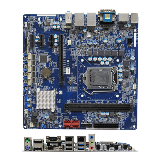
Page 8: Layout Diagram
⚫ 1*3-jack audio connector Internal I/O Connectors& Headers: ⚫ 1*24-pin main power connector ⚫ 1*4-pin 12V power connector ⚫ 1*CPUFAN connector & 1* SYSFAN connector ⚫ 1*Front panel audio header ⚫ 1*SPDIF-out header ⚫ 1*Front panel header ⚫ 1*9-Pin USB 2.0/1.1 header for 2* USB 2.0/1.1 ports ⚫... - Page 9 (SODIMM1/2) Serial Port Headers (COM5~6) HDMI Port Connector M.2 Socket 3 Connector *Full-size (MH1/2) Mini-PCIE/MSATA RJ-45 LAN Ports Intel H110 Chipset Slot (MPE1) Over USB 2.0 USB 3.0 Ports Headers USB 2.0 Virtical Connector *SIM Card LINE-OUT Slot Front Panel...
- Page 10 Motherboard Jumper Position JCOMP2 JCOMP1 JCOMP3 EDP_BKPWR EDP_LCDPWR MPE_PWR JP_TEST JBAT JP1: Jumper & Header Combo Block...
- Page 11 Jumper Jumper Name Description JCOMP1 COM1 Port Pin9 Function Select 4-pin Block JCOMP2 COM2 Port Pin9 Function Select 4-pin Block JCOMP3 COM3 Port Pin9 Function Select 4-pin Block JBAT Clear CMOS RAM Settings 2-pin Block Pin(1-2): Case Open Message Display Function 8-pin Block Pin(3-4): ATX Mode / AT Mode Select Pin(5&6):LAN1 Activity LED Header...
- Page 12 Headers Header Name Description Front Panel Header(PWR LED/ HD 9-pin Block LED/Power Button /Reset) USB1 USB Header X1 9-pin Block USB2 USB Header X1 4-pin Block PS2KBMS1 PS2 Keyboard & Mouse Header 6-pin Block SMBUS SMBUS Header 5-pin Block GPIO1 GPIO Header 10-pin Block COM5/6...
-
Page 13: Chapter 2 Hardware Installation
Chapter 2 Hardware Installation 2-1 Jumper Setting JCOMP1 (4-pin): COM1 Port Pin9 Function Select (2.54 pitch) JCOMP1 → JCOMP1 COM1 Port Pin-9 5 3 1 5 3 1 6 4 2 6 4 2 2-4 Closed: 3-4 Closed: 4-6 Closed: PIN9=RS232;... - Page 14 JBAT (2-pin): Clear CMOS RAM Settings (2.54 pitch) → JBAT Clear CMOS 1-2 Open: Normal (Default); 1-2 Closed:Clear CMOS Settings. Pin (1-2) of JP1 (8-pin):Case Open Message Display Function Select (2.0 pitch) → Pin(1-2) of JP1 Case Open Detect Pin1 1-2 Open: Normal (Default);...
- Page 15 Pin (3-4) of JP1 (8-pin): ATX Mode/ AT Mode Select (2.0 pitch) → Pin(3-4) of JP1 ATX/AT Mode Select Pin1 3-4 Open: ATX Mode Selected (Default); Pin1 3-4 Close : AT Mode Selected. *ATX Mode Selected: Press power button to power on after power input ready; AT Mode Selected: Directly power on as power input ready.
- Page 16 Pin (7-8) of JP1 (8-pin): LAN2 Active LED Header (2.0 pitch) → Pin(7-8) of JP1 LAN2 Activity LED Pin1 7-8 Open: Normal (Default); Pin1 7-8 Close : LAN2 Active LED selected. JP2 (2-pin): ME Features Select (2.54 pitch) → ME Features Select 1-2 Open: Enable ME Features;...
- Page 17 MPE_PWR (3-pin): MPE1 Slot VCC 3.3V/3.3 VSB Select (2.0 pitch) → MPE_PWR MPE1 Slot VCC 1-2 Closed: MPE1 Slot VCC= 3.3V; 2-3 Closed: MPE1 Slot VCC= 3.3VSB. EDP_BKPWR (4-pin): EDP Backlight VCC 3.3V/5V/12V (2.0 pitch) → EDP_BKPWR EDP Backlight VCC 5 3 1 5 3 1 6 4 2...
- Page 18 EDP_ LCDPWR (4-pin): EDP LCD Panel VCC 3.3V/5V/12V (2.0 pitch) → EDP_LCDPWR EDP LCD Panel VCC 5 3 1 5 3 1 6 4 2 6 4 2 2-4 Closed: 3-4 Closed: 4-6 Closed: EDP LCD EDP LCD EDP LCD VCC =3V;...
-
Page 19: Connectors And Headers
2-2-1 Connectors (1) Rear Panel Connectors Serial Port(COM3) Serial Port(COM1) RJ-45 LAN Ports Line-IN Line-OUT MIC-IN Serial Port HDMI Port (COM2) USB 3.0 Ports Icon Name Function Mainly for user to connect external MODEM or other devices that supports COM Port Serial Communications Interface. - Page 20 (2) COM1 (9-pin Block): RS232/422/485 Port COM1 port can function as RS232/422/485 port. In normal settings COM1 functions as RS232 port. With compatible COM cable COM1 can function as RS422 or RS 485 port. User also needs to go to BIOS to set ‘Transmission Mode Select’ for COM1 at first, before using specialized cable to connect different pins of this port.
- Page 21 (4) ATXPWR1 (24-pin block): Power Connector Row2 Pin13 Pin1 Row1 PIN ROW1 ROW2 +3.3V +3.3V +3.3V -12V Power Supply On Power OK +5V Stand by +5V +12V +12V +3.3V (5) ATX12V1 (4-pin block): ATX12V Type Power Connector Pin4 Pin1 Pin2 Pin No.
- Page 22 (6) SATA1/SATA2 (7-pin): SATA III Port connector SATA1&SATA2 are high-speed SATAIII port that supports 6 GB/s transfer rate. Pin No. Defnition (7) CPUFAN1/SYSFAN1 (4-pin): Fan Connector (2.54 pitch) Control Fan Speed +12V Fan Power Pin1 Pin1 CPUFAN1 SYSFAN1...
- Page 23 (8) EDP1(40-pin): EDP Connector (1.25 pitch) Pin 1 Pin21 Pin No. Pin Define Pin No. Pin Define Pin 1 Pin 21 Pin 2 Pin 22 Pin 3 EDP_DATA3N Pin 23 Pin 4 EDP_DATA3P Pin 24 Pin 5 Pin 25 Pin 6 EDP_DATA2N Pin 26 Pin 7...
-
Page 24: Headers
2-2-2 Headers (1) FP1 (9-pin): Front Panel Header (2.54 pitch) Pin 1 HDD LED+ PWR LED+ HDD LED PWR LED - PWRSW RSTSW (2) USB1/USB2 (9-pin): USB 2.0 Port Headers (2.54 pitch) USB1 → USB 2.0 Port *2 Pin 1 -DATA -DATA +DATA... - Page 25 (3) PS2KBMS1 (6-pin): PS/2 Keyboard & Mouse Header (2.54 pitch) Pin1 (4) SMBUS (5-Pin): SMBUS Header (2.54 pitch) Pin1...
- Page 26 (5) GPIO1(10-pin): GPIO Header (2.0 pitch) Pin 1 (6) COM5/COM6 (9-pin): RS232 Serial Port Header (2.54 pitch) COM5 COM6 Pin NO. RS232 Pin NO. RS232 Pin 1 Pin 2 Pin 3 Pin 4 Pin 5 SOUT Pin 6 Pin 7 Pin 8 Pin 9 Pin 1...
-
Page 27: Chapter 3 Introducing Bios
Chapter 3 Introducing BIOS Notice! The BIOS options in this manual are for reference only. Different configurations may lead to difference in BIOS screen and BIOS screens in manuals are usually the first BIOS version when the board is released and may be different from your purchased motherboard. Users are welcome to download the latest BIOS version form our official website. -
Page 28: Bios Menu Screen
BIOS Menu Screen The following diagram show a general BIOS menu screen: Menu Bar General Help Items Current Setting Value Menu Items Function Keys... -
Page 29: Function Keys
Function Keys In the above BIOS Setup main menu of, you can see several options. We will explain these options step by step in the following pages of this chapter, but let us first see a short description of the function keys you may use here: ⚫... -
Page 30: Main Menu
Chipset To change chipset configuration Security Password settings Boot To change boot settings Save & Exit Save setting, loading and exit options. User can press the right or left arrow key on the keyboard to switch from menu bar. The selected one is highlighted. Main Menu Main menu screen includes some basic system information. -
Page 31: Advanced Menu
3-7 Advanced Menu CPU Configuration Press [Enter] to make settings for the following sub-items: Intel Virtualization Technology The optional settings: [Disabled]; [Enabled]. When set as [Enabled], a VMM can utilize the additional hardware capabilities provided by Vanderpool Technology. Hardware Prefetcher Use this item to turn on/off the MLC streamer prefecher. - Page 32 C states Use this item to enable or disable CPU Power Management. The optional settings: [Disabled]; [Enabled]. When set as [Enabled], it allows CPU to go to C states when it’s not 100% utilized. Package C State Limit Use this item to select the Maximum Package C State Limit Setting. The optional settings: [C0/C1];...
- Page 33 PCH-FW Configuration Press [Enter] to configure Management Engine Technology Parameters and make settings in the following sub-item: ME Firmware Version ME Firmware Mode ME Firmware SKU PTT Capability / State TPM Device Selection Use this item to select TPM device. The optional settings: [dTPM];...
- Page 34 ACPI Sleep State Use this item to select the highest ACPI sleep state the system will enter when the suspend button is pressed. The optional settings are: [Suspend Disabled]; [S3 (Suspend to RAM)]. Wake-up Function Settings Press [Enter] to make settings for the following sub-items: Wake-up System With Fixed Time Use this item to enable or disable System wake on alarm event.
- Page 35 Ring Wake-up The optional settings: [Disabled]; [Enabled]. This function is supported when ‘ERP Support’ is set as [Disabled]. *Note: ► Super I/O Configuration Press [Enter] to make settings for the following sub-items: Super IO Configuration ERP Support The optional settings: [Disabled]; [Auto]. This item should be set as [Disabled] if you wish to have all active wake-up functions.
- Page 36 ► Serial Port 2 Configuration Press [Enter] to make settings for the following items: Serial Port Use this item to enable or disable Serial Port (COM). The optional settings: [Disabled]; [Enabled]. When set as [Enabled], user can make further settings in the following items: Device Settings Change Settings Use this item to select an optimal setting for Super IO Device.
- Page 37 ► Serial Port 5 Configuration Press [Enter] to make settings for the following items: Serial Port Use this item to enable or disable Serial Port (COM). The optional settings: [Disabled]; [Enabled]. When set as [Enabled], user can make further settings in the following items: Device Settings Change Settings Use this item to select an optimal setting for Super IO Device.
- Page 38 WatchDog Reset Timer Use this item to enable or disable WDT reset function. The optional settings: [Disabled]; [Enabled]. When set as [Enabled], the following sub-items shall appear: WatchDog Reset Timer Value User can select a value in the range of [4] to [255] seconds when ‘WatchDog Reset Timer Unit’...
- Page 39 PS2 KB/MS Connect Use this item to select PS2 connect primary device. The optional settings: [Keyboard First]; [Mouse First]. ► PC Health Status Press [Enter] to view current hardware health status, make further settings in ‘SmartFAN Configuration’ and set value in ‘Shutdown Temperature’. ►...
- Page 40 COM1 Console Redirection Use this item to enable or disable COM1 Console Redirection. The optional settings: [Disabled]; [Enabled]. When set as [Enabled], user can make further settings in the ‘Console Redirection Settings’ screen: Console Redirection Settings The settings specify how the host computer and the remote computer (which the user is using) will exchange data.
- Page 41 Stop Bits Stop bits indicate the end of a serial data packet. (A start bit indicates the beginning). The standard setting is 1 stop bit. Communication with slow devices may require more than 1 stop bit. The optional settings: [1]; [2]. Flow Control Flow control can prevent data loss from buffer overflow.
- Page 42 Serial Port for Out-of-Band Management/ Windows Emergency Management Services (EMS) Console Redirection The optional settings: [Disabled]; [Enabled]. When set as [Enabled], user can make further settings in ‘Console Redirection Settings’ screen: Console Redirection Settings The settings specify how the host computer and the remote computer (which the user is using) will exchange data.
- Page 43 Data Bits The default setting is: [8]. *This item may or may not show up, depending on different configuration. Parity The default setting is: [None]. *This item may or may not show up, depending on different configuration. Stop Bits The default setting is: [1]. *This item may or may not show up, depending on different configuration.
- Page 44 Media detect count Use this item to set number of times presence of media will be checked. Use either [+] / [-] or numeric keys to set the value. ► CSM Configuration Press [Enter] to make settings for the following sub-items: CSM Support Use this item to enable or disable CSM Support The optional settings: [Disabled];...
- Page 45 Select [Manual] you can set value for the following sub-item: ‘Device power-up delay in seconds’, the delay range in from 1 to 40 seconds, in one second increments. Intel(R) I211 Gigabit Network Connection - XX:XX:XX:XX:XX:XX This item shows current network brief information. Intel(R) Ethernet Connection (H) I219-LM - XX:XX:XX:XX:XX:XX...
-
Page 46: Chipset Menu
3-8 Chipset Menu ► System Agent (SA) Configuration Press [Enter] to make settings for the following sub-items: System Agent (SA) Configuration VT-d The optional settings: [Disable]; [Enabled]. ► Graphics Configuration Press [Enter] to make further settings for Graphics Configuration. Graphics Configuration Primary Display Use this item to select which of graphics device should be primary display. - Page 47 GTT Size The optional settings: [2MB]; [4MB]; [8MB]. Aperture Size The optional settings: [128MB]; [256MB]; [512MB]; [1024MB]. DVMT Pre-Allocated Use this item to select DVMT 5.0 Pre-Allocated (Fixed) Graphics Memory size used by the Internal Graphics Device. The optional settings: [32M]; [64M]; [96M]; [128M]; [160M]; [192M]; [224M]; [256M]; [288M];...
- Page 48 ► PEG Port Configuration Press [Enter] to make settings for the following sub-items: PEG Port Configuration PEG (PCIE1 Slot) Max Link Speed Use this item to configure PED 0:1:0 Max Speed. The optional settings: [Auto]; [Gen1]; [Gen2]; [Gen3]. Program PCIe ASPM after OpROM The optional settings: [Disabled];...
- Page 49 Wake on LAN Enable Use this item to enable or disable integrated LAN to wake the system. The optional settings: [Enabled]; [Disabled]. Onboard Lan2 Controller Use this item to enable or disable Device or Controller. The optional settings: [Disabled]; [Enabled]. MPE Slot Use this item to enable or disable Device or Controller.
-
Page 50: Security Menu
3-9 Security Menu Security menu allow users to change administrator password and user password settings. Administrator Password If there is no password present on system, please press [Enter] to create new administrator password. If password is present on system, please press [Enter] to verify old password then to clear/change password. - Page 51 Secure Boot Press [Enter] to make customized secure settings: System Mode Secure Boot Vendor Keys Secure Boot Secure Boot activated when Platform Key(PK) is enrolled, System mode is User/Deployed, and CSM function is disabled. The mode change requires platform reset. The optional settings: [Disabled];...
-
Page 52: Boot Menu
Save all Secure Boot variables Secure Boot variable/Size/Keys/Key Source Platform Key(PK)/Key Exchange Keys/Authorized Signatures/Forbidden Signatures/ Authorized TimeStamps/OsRecovery Signatures Use this item to enroll Factory Defaults or load certificates from a file: 1. Public Key Certificate: a) EFI_SIGNATURE_LIST b) EFI_ CERT_X509 (DER) c) EFI_ CERT_RSA2048 (bin) d) EFI_ CERT_SHAXXX 2. - Page 53 Boot Configuration Setup Prompt Timeout Use this item to set number of seconds to wait for setup activation key. 65535 (0xFFFF) means indefinite waiting. Bootup NumLock State Use this item to select keyboard NumLock state. The optional settings: [On]; [Off]. Quiet Boot The optional settings: [Disabled];...
-
Page 54: Save & Exit Menu
3-11 Save & Exit Menu Save Options: Save Changes and Reset This item allows user to reset the system after saving the changes. Discard Changes and Reset This item allows user to reset the system without saving any changes. Default Options: Restore Defaults Use this item to restore /load default values for all the setup options. - Page 55 Boot Override UEFI: Built-in EFI Shell Press this item to select the device as boot disk after save configuration and reset Launch EFI Shell from filesystem device Press this item to launch EFI Shell application (Shell.efi) from one of the available file system device.
Need help?
Do you have a question about the H110 and is the answer not in the manual?
Questions and answers