Hopewind hopeSun Series User Manual
String inverter
Hide thumbs
Also See for hopeSun Series:
- User manual (46 pages) ,
- Quick installation manual (2 pages) ,
- Quick installation manual (2 pages)
Table of Contents
Advertisement
Advertisement
Table of Contents

Related Manuals for Hopewind hopeSun Series


Summary of Contents for Hopewind hopeSun Series
- Page 3 Version: V1.2 Thank you for purchasing products designed and manufactured by Shenzhen Hopewind Technology Co., Ltd. (hereinafter referred to as “Hopewind”). We hope our products and this manual can meet your demands. Any suggestion for improvement shall be appreciated. Shenzhen Hopewind Technology Co., Ltd. reserves the copyright of this manual, and it shall be subject...
- Page 5 This manual is helpful for technicians who install, commission, operate and maintain string inverters of Hopewind. Suggest you view this manual carefully before use relative devices. Readers are required to have basic knowledge on electric components, wiring, signs and mechanical drawings.
-
Page 7: Table Of Contents
Contents 1 Safety Precautions ..........................1 1.1 Transport........................... 1 1.2 Storage ............................. 1 1.3 Installation ..........................2 1.4 Operating ..........................2 1.5 Maintenance ..........................3 2 Product Description .......................... 5 2.1 Product Introduction ........................5 2.1.1 Schematic........................... 5 2.1.2 Operating mode .......................... 7 2.2 System Configuration and Application .................. - Page 8 6 Inverter Instruction .......................... 39 6.1 Remove inverter ........................39 6.2 Replacement of inverter ......................39 6.3 Packaging inverter ........................39 6.4 Scrapped inverter........................39...
-
Page 9: Safety Precautions
Safety Precautions In this chapter, it describes the safety precautions that must be observed when installing, operating and maintaining the inverter. Please read them carefully before operation and follow them in operation process; otherwise it might cause damage to the inverter, generator, related equipments and/or serious injury or loss of life. -
Page 10: Installation
User Manual 1.3 Installation DANGER Before operating the internals of the string inverter, it must be confirmed that the input switch DC Switch of the string inverter and the circuit breaker corresponding to the AC side of the inverter are in the off state, and the string inverter is guaranteed. -
Page 11: Maintenance
1 Safety precautions 1.5 Maintenance DANGER Before maintenance, the AC output side circuit breaker must be disconnected, then the input switch DC Switch must be disconnected, and then wait for at least five minutes to operate the string inverter. In the maintenance process, please try to avoid unrelated personnel entering the maintenance site. Maintain the string inverter under the condition that you are familiar with the contents of this manual and have the appropriate tools and testing devices. -
Page 13: Product Description
The hopeSun series string inverter is a three-phase string-type grid-connected inverter independently developed by Hopewind Technology. Its main function is to convert the DC power generated by the PV string into AC power and feed it into the power grid. - Page 14 User Manual Current hall fuse MPPT circuit RCD leakage Input EMI current filter detection Three- BUS+ Output MPPT phase circuit inverter filter BUS- filter circuit fuse MPPT Input EMI circuit filter DC switch Figure 2-3 Schematic diagram of hopeSun 50KTL Current hall MPPT circuit...
-
Page 15: Operating Mode
2 Product Description MPPT circuit Fuse Current hall RCD leakage current Input EMI detection filter Three- BUS+ Output MPPT phase circuit inverter filter filter BUS- circuit MPPT circuit Input EMI filter MPPT circuit DC switch Figure 2-6 Schematic diagram of hopeSun 75KTL MPPT circuit Fuse Current hall... -
Page 16: System Configuration And Application
User Manual Operating mode Description 1) Standby mode mainly means that the external environment does not meet the operating conditions of the inverter. If the light is insufficient, the DC input switch is disconnected. In this mode, the inverter continuously self-tests and Standby enters the operating mode once the operating conditions are met. -
Page 17: Supported Grid Form
2 Product Description Power grid Central monitoring center hopeView Client Mobile Internet Internet WiFi/GPRS wireless module hopeCloud Box-type Internet transformer String inverter User load PV arrays Figure 2-11 Distributed photovoltaic power plant networking design 2.2.2 Supported grid form hopeSun 36KTL, hopeSun 40KTL, hopeSun 50KTL, hopeSun 60KTL, hopeSun 70KTL and hopeSun 75KTL support the form of power grids TN-S, TN-C, TN-C-S, TT, IT;... -
Page 18: Nameplate Label
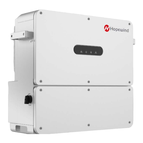
User Manual 2.4 Nameplate label (Note: The data is for reference only; please refer to the physical or technical agreement of the corresponding product) 2.5 Machine configuration This section shows the internal components of the string inverter, the back device, and the bottom interface. - Page 19 2 Product Description Label Device name LED indicator Upper door Lower door Figure 2-14 Front view of the whole machine The LED indicators from left to right are described as follows: Table 2-1 LED Indicator Description Indicator light Meaning Status Meaning The voltage of PV side is more than 200V, and Blue light on...
-
Page 20: Identification On The Package
User Manual Label Device name Handle Mounting rack Cooling fan Figure 2-15 Back view of the whole machine 60KTL, 60KTL-M, 70KTL, 70KTL-M, 75KTL and 80KTL-M 36KTL, 40KTL, 50KTL-M and 50KTL Label Device name DC SWITCH DC switch 1+ ~ 9(14)+ PV+ terminal block 1-~9(14)- PV- terminal block... -
Page 21: Warning Labels In Inverter
2 Product Description Stand upright Prohibition of tilting or turning and do not tilt. products Front facing of Back facing of the whole the whole machine machine 2.7 Warning Labels in Inverter In order to ensure the safety of the person and property when using the product and to avoid accidents, the following warning labels may be provided inside and outside the body of the string inverter to remind the user of the safety precautions during operation. -
Page 22: Technical Data
User Manual 2.8 Technical Data Model 36KTL 40 KTL 50KTL-M 50KTL Maximum input voltage 1100V Minimum working voltage 250V Working voltage range 250V~1000V MPPT full load working 540V~880V voltage range Input Rated input voltage 650V 770V 650V parameters Maximum input current 36A(12*3) /24A(12*2) 36A(12*3) per MPPT... - Page 23 2 Product Description Model 60KTL 70KTL 75 KTL 60KTL-M 70KTL-M 80KTL-M Maximum input voltage 1100V Minimum working voltage 250V Working voltage range 250V~1000V MPPT full load working 540V~880V voltage range Rated input voltage 650V 770V Input parameters 48A(12*4) 48A(12*4) Maximum input current 36A(12*3) 36A(12*3) per MPPT...
-
Page 24: Mechanical Parameters
70KTL-M hopeSun 80KTL-M Note: size does not contain hangers, handles, pads and other components. Dimensional error: + 10mm. Inverter structure and mounting rack installation size 650mm 207mm Figure 2-1 structural dimensions of hopeSun series (right, front, back, unit: mm) -
Page 25: Environmental Requirements
2 Product Description 2.10 Environmental requirements Transportation Requirements environment Type of shipping Waterways, railways, highways, aviation, etc. Ambient temperature -40℃~+70℃ ≤95%, at +40°C Relative humidity Mechanical condition The vibration should not exceed the following limits: 2Hz≤f<9Hz, displacement 7.5mm; 9Hz≤f<200Hz, acceleration 20m/s 200Hz≤f<500Hz, acceleration 40m/s Storage environment Requirements... -
Page 27: System Installation
. If you find any damage or omission, please contact Hopewind Technology as soon as possible, our staff will be happy to serve you in the first time. -
Page 28: Reserved Space Requirement
User Manual 3.4 Reserved Space Requirement When installing the string inverter, the space around the string inverter must be reserved for heat dissipation and maintenance. ≥200mm ≥300mm Figure 3-1 Single string inverter installation space When installing multiple string inverters in a same surface, the side by side installation is recommended. -
Page 29: Fixed Method
3 System Installation 3.5 Fixed method A hanging board is attached to the package of the string inverter. Fixed hanging board should be installed before the inverter is mounted and fastened on the hanging board. According to the actual installation environment, two installation modes can be selected, i.e. column-holding/rod-holding and wall-hanging. -
Page 30: Bracket Mounting
User Manual Before hanging the inverter, please confirm that the bearing range meets the requirements; Hang the inverter on the hanging plate and fasten the connecting plate and inverter from both sides with 4 PCS M8 screws (supplied accessories); The installation process ends and the actual effect is as shown below: Figure 3-5 String inverter screw mounting diagram 3.5.3 Bracket Mounting ... -
Page 31: Electrical Connections
3 System Installation 3.6 Electrical connections 3.6.1 Cable requirements The choice of cable should comply with relevant national standards and meet the load requirements. Power cable requirements Refer to the electrical data in the product data, and then consider the ambient temperature, current, margin and other factors to select the cable specifications. -
Page 32: Cable Selection
User Manual 3.6.2 Cable Selection Name Label Recommended Cable Note Specifications PV branch input 1+ ~9(14)+ Industry general photovoltaic cable, cable model: PV1-F. 1- ~9(14)- It is recommended to use 4.0mm copper cable for each PV + and PV branch. AC output cable A、B、C、N 4 core outdoor cable (A, B, C, N) or The AC output has only 1 waterproof... -
Page 33: Preparation Before Operation
3 System Installation 3.6.4 Preparation before operation DANGER When connecting cables, do not operate energized and follow the relevant requirements in “1 Safety Precautions”. Before connecting the cables, please complete the following preparations to avoid personal injury. Before making electrical connections, make sure that the "DC SWITCH" of the inverter is in the "OFF" state, otherwise the high voltage of the inverter may cause a shock hazard. -
Page 34: Open The Lower Door
User Manual 3.6.6 Open the lower door CAUTION Do not open the chassis door on the top of the inverter. Before the inverter opens the door, it must be ensured that the AC and DC are powered off. Please keep the 6 screws on the chassis door. Do not leave unused screws inside the chassis. Figure 3-11 Disassemble the lower door panel 3.6.7 Connect the AC output cable... -
Page 35: Connecting Communication Cable
3 System Installation 3.6.8 Connecting communication cable Choice of communication method The inverters support PLC communication mode and RS485 communication mode. Precautions PLC communication mode and RS485 communication mode can only choose one type, cannot be used at the same time ... -
Page 36: Connect The Dc Input Cable
User Manual 3.6.9 Connect the DC input cable In order to make full use of the DC input power, the PV strings of the same input MPPT should be identical in structure, including the same model, the same number of panels, the same tilt angle, and the same azimuth. DANGER When the sun shines on the panel, it will generate voltage, which may cause life-threatening. - Page 37 3 System Installation Crimp MC4 terminal step The input cable needs to be crimped into the MC4 terminal for connection to the string inverter PV+/PV- terminals. Before operation, ensure that “3.6.4 Preparation before Operation” has been completed. The positive and negative poles of the input cable are determined and identified. Note: Please do not judge the positive and negative according to the cable color in this manual.
-
Page 39: Commissioning Guide
Commissioning Guide 4.1 Check before starting DANGER Before proceeding to the next step of power on, please read carefully this manual "1 safety precautions" and do a detailed check according to the table below. In order to avoid danger, the multimeter and other instruments must be used to detect the voltage of the metal parts inside the casing (protective ground) of the string inverter. -
Page 40: Power-On System
User Manual 4.2 Power-on system To ensure that the electrical connection is completed, the power on operation can be performed and the inverter will be turned on. Step 1: Close the AC circuit breaker between the inverter and the power grid. Step 2: Put the inverter's "DC SWITCH"... -
Page 41: Maintenance And Troubleshooting
Output hardware Fault word the protection point set by the 2. If it occurs frequently, please overvoltage hardware. contact the Hopewind technician. 1. Normal work after resetting. Hardware overcurrent Unit inductor current is too 2. If it occurs frequently, please (secondary) large contact the Hopewind technician. - Page 42 Unit 1 hardware hardware-by-wave current limit 2. If it occurs frequently, please overcurrent time contact the Hopewind technician. Unit 1 current overcurrent and 1. Normal work after resetting. Unit 1 hardware hardware-by-wave current limit 2. If it occurs frequently, please...
- Page 43 1. Normal work after resetting. Hardware overcurrent exceeds hardware protection 2. If it occurs frequently, please (secondary) threshold contact the Hopewind technician. Phase A inductor current 1. Normal work after resetting. Phase A hardware triggers wave-by-wave 2. If it occurs frequently, please...
- Page 44 User Manual Name of failure / Fault word Fault/alarm reason Troubleshooting alarm 1. Check whether there is a fault such as a box trip on the AC side of The grid frequency exceeds the inverter through fault recording Grid overfrequency the over-frequency point set and event recording.
- Page 45 5 Maintenance and troubleshooting Name of failure / Fault word Fault/alarm reason Troubleshooting alarm 1, whether the detection module is DC input voltage exceeds the over allocated. DC high input voltage setting threshold. 2, check whether the input voltage detection circuit is normal. Grid connected relay Relay status error Detecting master slave relay status...
- Page 47 Inverter Instruction 6.1 Remove inverter Before operating, make sure that the circuit breaker between the inverter and the grid is disconnected, and the "DC SWITCH" is placed in the "OFF" state. Disconnect all electrical connections to the inverter, including the AC output line, RS485 communication line, DC input line and protective ground.
- Page 49 Please contact us in advance if you want repair or alteration service. Contact Us Shenzhen Hopewind Technology Co., Ltd. Address: Building 5, Guanlong No. 2 Industrial Park, Xili, Nanshan District, Shenzhen, PR.China Website: www.hopewind.com...
Need help?
Do you have a question about the hopeSun Series and is the answer not in the manual?
Questions and answers