Table of Contents
Advertisement
Advertisement
Table of Contents
Troubleshooting

Related Manuals for Gigabyte GA-F2A88XM-D3H


Summary of Contents for Gigabyte GA-F2A88XM-D3H
- Page 1 GA-F2A88XM-D3H User's Manual Rev. 3101 12ME-F288M3H-3101R...
- Page 3 No part of this manual may be reproduced, copied, translated, transmitted, or published in any form or by any means without GIGABYTE's prior written permission. In order to assist in the use of this product, GIGABYTE provides the following types of documentations: For quick set-up of the product, read the Quick Installation Guide included with the product.
-
Page 4: Table Of Contents
Table of Contents Box Contents ........................6 Optional Items .........................6 GA-F2A88XM-D3H Motherboard Layout .................7 GA-F2A88XM-D3H Motherboard Block Diagram ............8 Chapter 1 Hardware Installation ..................9 Installation Precautions ..................9 ..................10 Installing the APU and APU Cooler ..............13 1-3-1 Installing the APU ....................13 1-3-2 Installing the CPU Cooler ..................15... - Page 5 Chapter 4 Drivers Installation ..................71 Installing Chipset Drivers ................71 Application Software ..................72 Technical Manuals ..................72 Contact ......................73 System ......................73 Download Center ................... 74 Chapter 5 Unique Features ...................75 BIOS Update Utilities ..................75 5-1-1 Updating the BIOS with the Q-Flash Utility .............75 5-1-2 Updating the BIOS with the @BIOS Utility .............78 EasyTune 6 ....................
-
Page 6: Box Contents
Box Contents GA-F2A88XM-D3H motherboard Motherboard driver disk User's Manual Quick Installation Guide Four SATA cables I/O Shield The box contents above are for reference only and the actual items shall depend on the product package you obtain. The box contents are subject to change without notice. -
Page 7: Ga-F2A88Xm-D3H Motherboard Layout
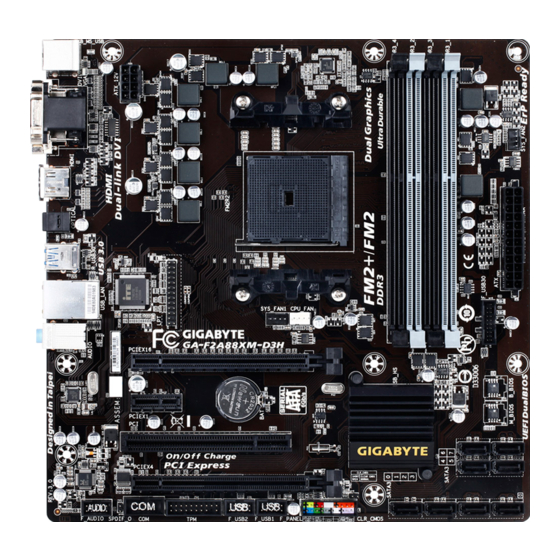
GA-F2A88XM-D3H Motherboard Layout KB_MS_USB ATX_12V DVI_VGA Socket FM2+ HDMI OPTICAL R_USB30 ® Super I/O GA-F2A88XM-D3H AUDIO PCIEX16 PCIEX1 B_BIOS Realtek ® M_BIOS AMD A88X SATA3 PCIEX4 CODEC SPDIF_O CLR_CMOS SATA3 F_AUDIO F_USB2 F_USB1 - 7 -... -
Page 8: Ga-F2A88Xm-D3H Motherboard Block Diagram
GA-F2A88XM-D3H Motherboard Block Diagram 1 PCI Express x16 PCIe CLK Dual Channel Memory AMD APU RJ45 HDMI Realtek ® DVI-D D-Sub PCI Express Bus 1 PCI Express x1 Dual BIOS PCI Express Bus 4 USB 3.0/2.0 8 USB 2.0/1.1 AMD A88X... -
Page 9: Chapter 1 Hardware Installation
Chapter 1 Hardware Installation Installation Precautions The motherboard contains numerous delicate electronic circuits and components which can become manual and follow these procedures: Prior to installation, make sure the chassis is suitable for the motherboard. warranty sticker provided by your dealer. These stickers are required for warranty validation. Always remove the AC power by unplugging the power cord from the power outlet before installing or removing the motherboard or other hardware components. - Page 10 The maximum 64 GB of system memory can be supported using 16 GB or above memory modules. GIGABYTE will update the memory support list on the of cial website when the memory modules are available on the market.
- Page 11 Storage Interface Chipset: 8 x SATA 6Gb/s connectors Support for RAID 0, RAID 1, RAID 5, RAID 10, and JBOD Chipset: 4 USB 3.0/2.0 ports 2 ports on the back panel, 2 ports available through the internal USB header 8 USB 2.0/1.1 ports 4 ports on the back panel, 4 ports available through the internal USB headers Internal 1 x 24-pin ATX main power connector...
- Page 12 Unique Features Support for @BIOS Support for Q-Flash Support for Xpress Install Support for EasyTune Available functions in EasyTune may differ by motherboard model. Support for Smart Recovery 2 Support for O /OFF Charge Bundled orton ® Internet Security OEM version Software Operating Support for indows 8.1/7 32-bit/64-bit...
-
Page 13: Installing The Apu And Apu Cooler
Installing the APU and APU Cooler Read the following guidelines before you begin to install the APU: Make sure that the motherboard supports the APU. Always turn off the computer and unplug the power cord from the power outlet before installing the APU to prevent hardware damage. - Page 14 B. Follow the steps below to correctly install the APU into the motherboard APU socket. Before installing the APU, make sure to turn off the computer and unplug the power cord from the power outlet to prevent damage to the APU. APU orientation if this occurs.
-
Page 15: Installing The Cpu Cooler
1-3-2 Installing the CPU Cooler Follow the steps below to correctly install the APU cooler on the motherboard. Step 1: Step 2: Apply an even and thin layer of thermal grease on Hook the APU cooler clip to the mounting lug on the surface of the installed APU. -
Page 16: Installing The Memory
Installing the Memory Read the following guidelines before you begin to install the memory: Make sure that the motherboard supports the memory. It is recommended that memory of the same capacity, brand, speed, and chips be used. Always turn off the computer and unplug the power cord from the power outlet before installing the memory to prevent hardware damage. -
Page 17: Installing A Memory
1-4-2 Installing a Memory Before installing a memory module, make sure to turn off the computer and unplug the power cord from the power outlet to prevent damage to the memory module. DDR3 and DDR2 DIMMs are not compatible to each other or DDR DIMMs. Be sure to install DDR3 DIMMs on this motherboard. DDR3 DIMM your memory modules in the memory sockets. -
Page 18: Installing An Expansion Card
Installing an Expansion Card Read the following guidelines before you begin to install an expansion card: Make sure the motherboard supports the expansion card. Carefully read the manual that came with your expansion card. Always turn off the computer and unplug the power cord from the power outlet before installing an expansion card to prevent hardware damage. - Page 19 Combining the onboard GPU with a discrete graphics card, AMD's Dual Graphics technology can provide Dual Graphics system. A. System Requirements - AMD A series processor - An AMD Radeon ™ Step 1: Observe the steps in "1-5 Installing an Expansion Card" and install an AMD Dual Graphics technology-supported graphics card on the PCIEX16 slot.
-
Page 20: Back Panel Connectors
Back Panel Connectors USB 2.0/1.1 Port PS/2 Keyboard/Mouse Port Use this port to connect a PS/2 mouse or keyboard. D-Sub Port The D-Sub port supports a 15-pin D-Sub connector and supports a maximum resolution of 1920x1200 Connect a monitor that supports D-Sub connection to this port. DVI-D Port (Note 1) Connect a monitor that supports DVI-D connection to this port. - Page 21 during the BIOS Setup or POST process. B. Playback of Blu-ray Disc ™ In order to get better playback quality, when playing the Blu-ray Disc ™ , refer to the recommended system AMD A series processors Optical S/PDIF Out Connector This connector provides digital audio out to an external audio system that supports digital optical audio.
-
Page 22: Internal Connectors
Internal Connectors ATX_12V F_AUDIO SPDIF_O CPU_FAN F_USB30 SYS_FAN1/2 F_USB1/F_USB2 SATA3 0/1/2/3/4/5/6/7 CLR_CMOS F_PANEL Read the following guidelines before connecting external devices: First make sure your devices are compliant with the connectors you wish to connect. Before installing the devices, be sure to turn off the devices and your computer. Unplug the power cord from the power outlet to prevent damage to the devices. - Page 23 1/2) ATX_12V/ATX (2x4 12V Power Connector and 2x12 Main Power Connector) off and all devices are properly installed. The power connector possesses a foolproof design. Connect the power supply cable to the power connector in the correct orientation. The 12V power connector mainly supplies power to the CPU. If the 12V power connector is not connected, the computer will not start.
- Page 24 3/4) CPU_FAN/SYS_FAN1/SYS_FAN2 (Fan Headers) All fan headers on this motherboard are 4-pin. Most fan headers possess a foolproof insertion design. optimum heat dissipation, it is recommended that a system fan be installed inside the chassis. +12V Sense Speed Control Speed Control Sense Reserve Be sure to connect fan cables to the fan headers to prevent your APU and system from...
- Page 25 6) SATA3 0/1/2/3/4/5/6/7 (SATA 6Gb/s Connectors) The SATA connectors conform to SATA 6Gb/s standard and are compatible with SATA 3Gb/s and SATA 1.5Gb/s standard. Each SATA connector supports a single SATA device. The AMD Chipset supports RAID 0, SATA3 SATA3 0 1 2 3 are to be used, the total number of hard drives must be an even number.
- Page 26 8) F_PANEL (Front Panel Header) Connect the power switch, reset switch, speaker, chassis intrusion switch/sensor and system status indicator before connecting the cables. Power LED Power Switch Speaker Hard Drive Reset Power LED Activity LED Switch Chassis Intrusion Header PLED/PWR_LED System Status LED Connects to the power status indicator on the chassis front panel.
- Page 27 9) F_AUDIO (Front Panel Audio Header) your chassis front panel audio module to this header. Make sure the wire assignments of the module connector match the pin assignments of the motherboard header. Incorrect connection between the module connector and the motherboard header will make the device unable to work or even damage it. For HD Front Panel Audio: For AC'97 Front Panel Audio: MIC2_L...
- Page 28 11) F_USB30 (USB 3.0/2.0 Header) optional 3.5" front panel that provides two USB 3.0/2.0 ports, please contact the local dealer. VBUS SSRX1- SSRX1+ SSTX2+ SSTX1- SSTX2- SSTX1+ SSRX2+ SSRX2- VBUS 12) F_USB1/F_USB2 (USB 2.0/1.1 Headers) optional USB bracket. For purchasing the optional USB bracket, please contact the local dealer. USB DX- USB DY- USB DX+...
- Page 29 13) COM (Serial Port Header) The COM header can provide one serial port via an optional COM port cable. For purchasing the optional COM port cable, please contact the local dealer. 14) LPT (Parallel Port Header) The LPT header can provide one parallel port via an optional LPT port cable. For purchasing the optional LPT port cable, please contact the local dealer.
- Page 30 15) TPM (Trusted Platform Module Header) LCLK LAD0 LFRAME LRESET SB3V SERIRQ LAD3 LAD2 VCC3 LAD1 SUSCLK Hardware Installation - 30 -...
-
Page 31: Chapter 2 Bios Setup
BIOS includes a BIOS Setup program that allows To upgrade the BIOS, use either the GIGABYTE Q-Flash or @BIOS utility. Q-Flash allows the user to quickly and easily upgrade or back up BIOS without entering the operating system. -
Page 32: Startup Screen
Startup Screen The following startup Logo screen will appear when the computer boots. Function Keys arrow key < The system will boot from the device immediately. will still be based on BIOS Setup settings. BIOS Setup - 32 -... -
Page 33: The Main Menu
The Main Menu to accept or enter a sub-menu. Or you can use your mouse to select the item you want. Setup Menus Enter Q-Flash Select Default Language Help Function Keys Current Settings BIOS Setup Program Function Keys < Move the selection bar to select a setup menu <... - Page 34 BIOS Setup Menus M.I.T. system/CPU temperatures, voltages, and fan speeds. System Information also displays information on the devices connected to the SATA ports. BIOS Features display adapter. Peripherals Power Management Save & Exit Save all the changes made in the BIOS Setup program to the CMOS and exit BIOS Setup. You can save BIOS Setup - 34 -...
- Page 35 M.I.T. to CPU, chipset, or memory and reduce the useful life of these components. This page is for advanced users only and we recommend you not to alter the default settings to prevent system instability or This section provides information on the BIOS version, CPU base clock, CPU frequency, memory frequency, - 35 - BIOS Setup...
- Page 36 M.I.T. Current Status This screen provides information on CPU/memory frequencies/parameters. Advanced Frequency Settings CPU Clock Control It is highly recommended that the CPU frequency be set in accordance with the CPU Processor Graphics Clock CPU NorthBridge Frequency CPU Clock Ratio Allows you to alter the clock ratio for the installed CPU.
- Page 37 Advanced CPU Core Features CPU Clock Ratio, CPU Frequency The settings above are synchronous to those under the same items on the Advanced Frequency Settings menu. Core Performance Boost (Note) Turbo Performance Boost Ratio Core Performance Boost Ratio Allows you alter the ratio for the CPB. The adjustable range is dependent on the CPU being installed. Enabled Lets the AMD Cool'n'Quiet driver dynamically adjust the CPU clock and VID to reduce Disabled...
- Page 38 CPU core Control Allows you to determine whether to manually enable/disable CPU cores. Automatic mode allows the BIOS (Note) enabled. (Note) System Memory Multiplier Allows you to set the system memory multiplier. Auto sets memory multiplier according to memory SPD Memory Frequency (MHz) This value is automatically adjusted according to the CPU Clock Control and System Memory Multiplier settings.
- Page 39 Advanced Memory Settings , System Memory Multiplier, Memory Frequency(MHz) (Note) The settings above are synchronous to those under the same items on the Advanced Frequency Settings menu. Memory Timing Mode Manual and Advanced Manual allows the Channel Interleaving, Rank Interleaving, and memory timing Extreme Memory Pro le (X.M.P.) is set to Disabled, the to Pro le1 or Pro le2, the value is displayed according to the SPD data on the XMP memory.
- Page 40 Channel A/B Memory Sub Timings This sub-menu provides memory timing settings for each channel of memory. This sub-menu provides memory Memory Timing Mode is set to Manual or Advanced Manual to boot after you make changes on the memory timings. If this occurs, please reset the board to default values Advanced Voltage Settings This sub-menu allows you to set CPU, chipset and memory voltages.
- Page 41 PC Health Status Reset Case Open Status Enabled Clears the record of previous chassis intrusion status and the Case Open Case Open Displays the detection status of the chassis intrusion detection device attached to the motherboard CI clear the chassis intrusion status record, set Reset Case Open Status to Enabled, save the settings to the CMOS, and then restart your system.
- Page 42 CPU Vcore/DRAM Voltage/+3.3V/+5V/+12V Displays the current system voltages. CPU/System Temperature Displays current CPU/system temperature. CPU/System Fan Speed Displays current CPU/system fan speeds. CPU Temperature Warning C/140 F, 70 C/158 F, 80 C/176 F, 90 C/194 CPU/System Fan Fail Warning Allows the system to emit warning sound if the CPU fan or system fan are not connected or fail. Check CPU Fan Speed Control Allows you to determine whether to enable the CPU fan speed control function and adjust the fan speed.
- Page 43 Miscellaneous Settings Allows you to set the operation mode of the PCI Express slots to Gen 1, Gen 2, or Gen 3. Actual operation Auto 3DMark01 Boost - 43 - BIOS Setup...
-
Page 44: System Information
System Information This section provides information on your motherboard model and BIOS version. You can also select the default language used by the BIOS and manually set the system time. System Language Selects the default language used by the BIOS. System Date value. -
Page 45: Bios Features
BIOS Features Boot Option Priorities Boot Option #1 Boot Option #2 Hard Drive BBS Priorities submenu will be presented here. string. - 45 - BIOS Setup... - Page 46 A password is required for booting the system and for entering the BIOS Setup Full Screen LOGO Show Allows you to determine whether to display the GIGABYTE Logo at system startup. Disabled skips the Fast Boot Enables or disables Fast Boot to shorten the OS boot process. Ultra Fast provides the fastest bootup VGA Support Allows you to select which type of operating system to boot.
- Page 47 CSM Support Windows 8 Features is set to Windows 8 or Windows 8 WH L. Boot Mode Selection Allows you to select which type of operating system to boot. UEFI and Legacy Allows booting from operating systems that support legacy option ROM or UEFI Legacy Only Allows booting from operating systems that only support legacy Option ROM.
- Page 48 Administrator Password BIOS Setup. Differing from the user password, the administrator password allows you to make changes to all BIOS settings. User Password Setup. However, the user password only allows you to make changes to certain BIOS settings but not all. BIOS Setup - 48 -...
-
Page 49: Peripherals
Peripherals IOMMU OnChip USB Controller HD Audio Azalia Device If you wish to install a 3rd party add-in audio card instead of using the onboard audio, set this item to Disabled. Legacy USB Support XHCI Hand-off Determines whether to enable XHCI Hand-off feature for an operating system without XHCI Hand-off EHCI Hand-off Determines whether to enable EHCI Hand-off feature for an operating system without EHCI Hand-off Port 60/64 Emulation... - Page 50 Primary Video Device card or the onboard graphics. display. Integrated Graphics Enables or disables the onboard graphics function. Auto The BIOS will automatically enable or disable the onboard graphics depending on Disabled Disables the onboard graphics. Force Always activates the onboard graphics, whether or not a PCI Express card is installed.
- Page 51 OnChip SATA Channel OnChip SATA Type to AHCI mode. RAID Enables RAID for the SATA controller. OnChip SATA Port4-7 Type (SATA3 4~SATA3 7 connectors) OnChip SATA Type is set to RAID or AHCI mode of the integrated SATA3 4~SATA3 7 connectors. As SATA Type The mode depends on the OnChip SATA Type PORT0 Hot Plug~PORT7 Hot Plug SATA Power on PORT0~SATA Power on PORT7...
- Page 52 parallel port. Serial Port A Parallel Port Device Mode Parallel Port is set to Enabled. It allows you to select an operating BIOS Setup - 52 -...
-
Page 53: Power Management
Power Management Resume by Alarm If enabled, set the date and time as following: AC power, or the settings may not be effective. HPET Timer Soft-Off by PWR-BTTN Delay 4 Sec. Press and hold the power button for 4 seconds to turn off the system. If the power button is pressed for less than 4 seconds, the system will enter suspend mode. - Page 54 Power On Password Set the password when Power On By Keyboard is set to Password. again without entering the password to clear the password settings. Power On By Mouse Allows the system to be turned on by a PS/2 mouse wake-up event. Move Move the mouse to turn on the system.
-
Page 55: Save & Exit
Save & Exit Save & Exit Setup Yes. This saves the changes to the CMOS and exits the BIOS Setup program. Select No Exit Without Saving Yes. This exits the BIOS Setup without saving the changes made in BIOS Setup to the CMOS. Select No Load Optimized Defaults Yes to load the optimal BIOS default settings. - Page 56 BIOS Setup - 56 -...
- Page 57 RAID Levels RAID 0 RAID 1 RAID 5 RAID 10 Minimum Drives Array Capacity drive smallest drive the smallest drive smallest drive Fault Tolerance D. Install the SATA RAID/AHCI driver and operating system Before you begin Motherboard driver disk. A. Installing SATA hard drive(s) in your computer Attach one end of the SATA signal cable to the rear of the SATA hard drive and the other end to available SATA port on the motherboard.
- Page 58 Step 1: OnChip SATA Channel is enabled under . To enable RAID for the SATA3 0/1/2/3 connectors, set OnChip SATA Type to RAID. To enable RAID for the SATA3 4~SATA3 7 connectors, set OnChip SATA Type to RAID and set OnChip SATA Port4-7 Type to As SATA Type Figure 1 Step 2: and exit BIOS Setup.
- Page 59 \BootDrv\UEFI RAID Utility folder in your motherboard driver Step 1: In BIOS Setup, go to BIOS Features and set Windows 8 Features to Windows 8 and CSM Support to Never. Figure 2 Running the UEFI RAID Utility as shown in Figure 3. To run the UEFI RAID utility, enter the following commands. You can enter the commands at Shell or EFI Shell version 2.31 [4.653] Current running mode 1.1.2...
- Page 60 Checking Disk Information LIST and DISK LIST displayed on the screen. rcadm -M -qa fs0:\> rcadm -M -qa Figure 4 Creating a RAID Array succeeded, the message which says "created sucessfully" will appear. rcadm -C -r0 -d 0 1 -s 40000 ("C"= s x0000 fs0:\>rcadm -C -r0 -d 0 1 -s 40000...
- Page 61 Deleting an Array rcadm -D -a 1 ("D"= YES to delete or NO fs0:\>rcadm -D -a 1 Delete Array 1, are you sure?(YES, NO): yes deleting array 1 deleting array //./Core1/Route0/Device 1 fs0:\> Figure 7 - 61 -...
- Page 62 Steps: After the POST memory test begins and before the operating system boot begins, look for a message which AMD-RAID Controller BIOS (6.1.1-00075) (c) 2012-2013 Advanced Micro Devices, Inc. * BIOS defaults restored. * 1--Legacy, 79GB, Normal (NA) 2--Legacy, 79GB, Normal (NA) Figure 8 Creating a RAID Array Create Array...
- Page 63 The selection bar will move to the Disks section on the right of the screen. Select the hard drives to be included and the selection bar will move to the User Input RAID0: Stripe set - distributes space across disks for higher performance Arrays Disks 0-00, 79GB, Ready...
- Page 64 Read and Write-back Caching. (Some data may be lost in a crash) Arrays 0-00, 79GB, Ready 1-01, 79GB, Ready Create Array Disks: 0, 1 Type: RAID 0 Total Size: 158GB Cachin Mode: Read/Write User Input Select Caching Mode Available Keys Read/Write <...
- Page 65 Deleting an Array The Delete Array(s) menu option allows for deletion of disk array assignments. Deleting an existing disk array could result in loss of data. Record all array information including the 1. Select Delete Array(s) in the Main Menu 2.
-
Page 66: Installing The Sata Raid/Ahci Driver And Operating System
Installing the SATA RAID/AHCI Driver and Operating System A. Installing Windows Step 1: You need to install the SATA RAID/AHCI driver during the OS installation. Use an alternative system to copy Hw8_A88 folder under BootDrv in the driver disk. Step 2: to load the driver appears, select Browse. - Page 67 B. Installing Windows XP (32-bit) \BootDrv\Hxp Steps: 1: Use an alternative system and insert the motherboard driver disk. 2: From your optical drive folder, double click the Menu.exe BootDrv folder. A Command Prompt window will open similar to that in Figure 2. For example, from the menu in Figure 2, for the AMD A88X, select 6) hseries AHCI/RAID<A85>for XP.
- Page 68 Step 1: "Press F6 if you need to install a 3rd party SCSI or RAID driver." A screen will then appear asking you to specify Step 2: to that in Figure 3 will appear. Select AMD AHCI Compatible RAID Controller-x86 platform Windows Setup using a device support disk provided by an adapter manufacturer.
- Page 69 Rebuilding is the process of restoring data to a hard drive from other drives in the array. Rebuilding applies only to fault-tolerant arrays such as RAID 1, RAID 5, and RAID 10 arrays. To replace the old drive, make sure to use a new drive of equal or greater capacity.
- Page 70 - 70 -...
-
Page 71: Chapter 4 Drivers Installation
After "Xpress Install" installs all of the drivers, a dialog box will appear asking whether to install new GIGABYTE utilities. Click Yes to automatically install the utilities. Or click No if you want to manually select the utilities to install on the Application Software page later. -
Page 72: Application Software
Application Software This page displays all the utilities and applications that GIGABYTE develops and some free software. You can click the Install button on the right of an item to install it. Technical Manuals This page provides the content descriptions for this driver disk. -
Page 73: Contact
Contact the URL on this page to link to the GIGABYTE website. System This page provides the basic system information. - 73 - Drivers Installation... -
Page 74: Download Center
Download Center To update the BIOS, drivers, or applications, click the Download Center button to link to the GIGABYTE website. The latest version of the BIOS, drivers, or applications will be displayed. Drivers Installation - 74 -... -
Page 75: Chapter 5 Unique Features
Chapter 5 Unique Features BIOS Update Utilities GIGABYTE motherboards provide two unique BIOS update tools, Q-Flash and @BIOS . GIGABYTE Q-Flash ™ ™ and @BIOS are easy-to-use and allow you to update the BIOS without the need to enter MS-DOS mode. - Page 76 B. Updating the BIOS Step 1: Update BIOS From Drive. The Save Main BIOS to Drive Select USB Flash Drive. Q-Flash Utility v1.05 Model Name : F2A88XM-D3H BIOS Version : F7c BIOS Date : 11/27/2014 Flash Type/Size : Winbond 25X/Q Series Update BIOS From Drive Save BIOS to Drive Select Device...
- Page 77 Step 4: Load Optimized Defaults on the Save & Exit so we recommend that you reload BIOS defaults. Select Yes to load BIOS defaults Step 5: Select Save & Exit Setup Yes to save settings to CMOS and exit BIOS Setup.
-
Page 78: Updating The Bios With The @Bios Utility
BIOS update. corrupted BIOS or a system that is unable to start. GIGABYTE product warranty does not cover any BIOS damage or system failure resulting from an inadequate B. Using @BIOS Click Update BIOS from GIGABYTE Server, select the @BIOS server site closest to your location and complete. -
Page 79: Easytune 6
EasyTune 6 includes tabbed pages for CPU and memory information, letting users read their system-related information without the need to install additional software. The EasyTune 6 Interface Tabs Information Description tab provides information on the installed CPU and motherboard. Memory Tuner tab allows you to change memory settings and voltages. -
Page 80: Smart Recovery 2
Smart Recovery 2 The Smart Recovery 2 main menu: Button Description Allows you to select the source and destination Settings partition Allows you to perform the backup immediately File image Recovery... System Allows you to recover your system from the backup image Recovery... - Page 81 Recovering your system with Smart Recovery 2 (Windows 8.1/7 Steps: 1. Click the File Recovery button on the main menu. 2. Select the location where your backup is saved. 3. Use the time slider to select a time point. 4. Select a partition backup created on the selected time point and click Restore.
- Page 82 Unique Features - 82 -...
-
Page 83: Chapter 6 Appendix
Chapter 6 Appendix The motherboard provides three audio jacks on the back panel which support 2/4/5.1/7.1 -channel audio. The picture to the right shows the Line In default audio jack assignments. Front Speaker Out capability that allows the user to change the function for each jack Mic In through the audio driver. - Page 84 The pictures to the right show the 7.1-channel speaker 7.1-Channel Speakers: Front Speaker Out Rear Speaker Out Center/Subwoofer Speaker Out Side Speaker Out Step 2: Connect an audio device to an audio jack. The The current connected device is dialog box appears. Select the device according to the type of device you connect.
- Page 85 C. Activating an AC'97 Front Panel Audio Module If your chassis provides an AC'97 front panel audio module, to activate the AC'97 functionality, click the tool icon on the tab. On the Connector Settings dialog box, select the Disable front panel jack detection check box.
- Page 86 The S/PDIF Out jack can transmit audio signals to an external decoder for decoding to get the best audio quality. Connect a S/PDIF optical cable to the corresponding S/PDIF out connector as shown below and an external decoder for transmitting the S/PDIF digital audio signals. Connects to a S/PDIF optical cable On the Digital Output(Optical) screen , click the Default Format tab and then select the sample rate and...
- Page 87 Step 1: HD Audio Manager icon Double-click the icon to access the HD Audio Manager. Step 2: back panel cannot be used at the same time. Step 3: Go to the Microphone screen. Do not mute the recording volume, or you'll not be able to record the sound. To hear the sound being recorded during the recording process, do not mute the playback volume.
- Page 88 Step 5: To open the Sound Recorder, move the mouse cursor to the bottom left corner of the screen, click the Start icon to switch to the Start icon on the bottom left corner of the screen to access the Apps screen. Step 6: On this screen, click Sound Recorder for audio recording.
-
Page 89: Using The Sound Recorder
Step 2: On the Recording tab, right-click on an empty space and select Show Disabled Devices. Step 3: Stereo Mix item appears, right-click on this item and select Enable. Then set it as the default device. Step 4: Stereo Mix and use Sound Recorder to record the sound. 6-1-4 Using the Sound Recorder A. -
Page 90: Troubleshooting
In Device Manager, right-click on the computer name and select Scan for hardware changes Add New Hardware Wizard appears, click Cancel. Then install the onboard HD audio driver from the moth- erboard driver disk or download the audio driver from GIGABYTE's website to install. For more details, go to the page on our website and search for "onboard HD audio driver."... -
Page 91: Troubleshooting Procedure
6-2-2 Troubleshooting Procedure If you encounter any troubles during system startup, follow the troubleshooting procedure below to solve the problem. START Turn off the power. Remove all peripherals, connecting cables, and power cord etc. Make sure the motherboard does not short-circuit with the chassis or Isolate the short circuit. - Page 92 The power supply, CPU or CPU socket might fail. The graphics card, expansion slot, or monitor Check if there is display on your monitor. might fail. Turn off the computer. Plug in the keyboard and mouse and restart the computer. The keyboard or keyboard Check if the keyboard is working properly.
-
Page 93: Regulatory Statements
This document must not be copied without our written permission, and the contents there of must not be imparted information contained herein was accurate in all respects at the time of printing. GIGABYTE cannot, however, assume any responsibility for errors or omissions in this text. Also note that the information in this document is subject to change without notice and should not be construed as a commitment by GIGABYTE. - Page 94 Appendix - 94 -...
-
Page 95: Contact Us
Correo: soporte@gigabyte-usa.com TEL: +86-29-85531943 Tech. Support: http://rma.gigabyte.us FAX: +86-29-85510930 Shenyang Giga-Byte SINGAPORE PTE. LTD. - Singapore TEL: +86-24-83992342 FAX: +86-24-83992102 Thailand GIGABYTE TECHNOLOGY (INDIA) LIMITED - India Vietnam Saudi Arabia Gigabyte Technology Pty. Ltd. - Australia - 95 - Appendix... - Page 96 Poland Sweden Ukraine Italy Romania Spain Serbia Greece Kazakhstan Czech Republic You may go to the GIGABYTE website, select your language in the language list on the top right corner of the website. GIGABYTE eSupport http://esupport.gigabyte.com Appendix - 96 -...
Need help?
Do you have a question about the GA-F2A88XM-D3H and is the answer not in the manual?
Questions and answers