Table of Contents
Advertisement
Quick Links
Advertisement
Table of Contents

Related Manuals for iSystem ARM HSSTP


Summary of Contents for iSystem ARM HSSTP
- Page 1 ARM HSSTP Active Probe V1.6 User Manual...
- Page 2 This document and all documents accompanying it are copyrighted by iSYSTEM AG and all rights are reserved. Duplication of these documents is allowed for personal use. In all other cases, written consent from iSYSTEM is required. Copyright iSYSTEM AG.
-
Page 3: Table Of Contents
Device description ........................5 Setting Debug Interface Voltage Levels ................... 8 Further Active Probe Settings ....................8 Accessories ..........................10 IOM6 product line ........................10 ARM HSSTP Active Probe Accessories ................... 10 User notes ..........................11 Technical support ........................12... -
Page 4: Introduction
Scripts can also be executed directly from within winIDEA, thereby allowing the developer to extend its functionality. iSYSTEM's solutions run under the Microsoft® Windows® operating system or optionally within a Wine emulation under the Linux operating system. All our software can be downloaded from... -
Page 5: Important Safety Notice
Use this instrument only for its intended purpose as specified by this manual to prevent potential hazards. Use included power cord and power supply The enclosed power supply has been approved for use by iSYSTEM. Please contact iSYSTEM if you need to consider an alternative power. Use grounding wire Prior to applying power to either the BlueBox or the target, connect the device and the target system together with the included grounding wire. -
Page 6: Package Content
Package content The standard ARM HSSTP Active Probe kit (ordering code IC57125) is delivered with the following components: ARM HSSTP Samtec40 -> 20-pin JTAG 1m FNET Micro Cable Active Probe ARM Adapter Ordering code: Ordering code: BB- Ordering code: IC57125... -
Page 7: Specifications
80 x 55 x 18 mm Weight 0.125 kg OPERATION Communication interface to Blue Box iSYSTEM proprietary FNET Debug signal valid input voltage range 1.8V to 3.6V Power consumption Max. 2W (dependent on operation mode) Number of supported HSSTP lanes... -
Page 8: Operation
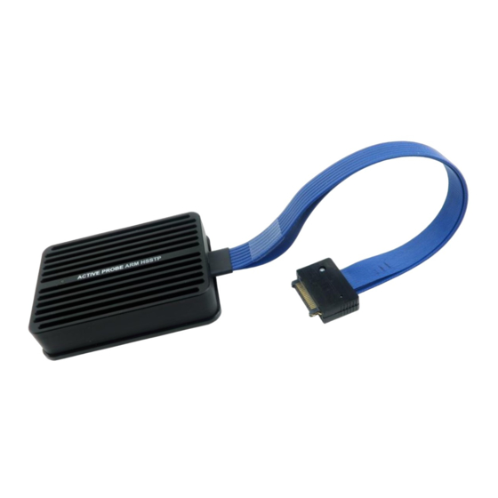
Operation Device overview Device description The front side features: A – 40-pin HSSTP connector with 20cm high-speed cable and the following pinout: Signal Signal Signal Signal Signal Signal description Direction Description Direction HSSTP Lane 4 Tx4_P VREF Reference Voltage Tx4_N HSSTP Lane 4 TCK/SWCLK... - Page 9 When powering on the system, switch the iC5700 on prior to powering on the target system; when powering down the system, power off the target microcontroller before powering off the iC5700. Use only original iSYSTEM accessories for powering and connecting with the iC5700. Consult with iSYSTEM before attempting to use any other accessory. IASAM40ARMPIN20 In conjunction with this Samtec40 to 20-pin JTAG ARM adapter delivered in the package, the Active Probe can be also connected to target development boards featuring a 20-pin, 2.54 mm...
- Page 10 Although it looks similar to the HDMI interface, the FNET Port is not compatible with HDMI or any HDMI accessories. Connecting iSYSTEM hardware to HDMI accessories will damage the hardware and will render the iSYSTEM hardware warranty void. ...
-
Page 11: Setting Debug Interface Voltage Levels
Setting Debug Interface Voltage Levels The voltage levels for the debug interface are configured within winIDEA via the menu option “Hardware -> Emulation Options”, selecting the “Hardware” tab in the “Emulations Options” dialog window, as shown below. The logic for the debug interface can be powered directly from the Active Probe (recommended setting) by selecting the right radio-button (as shown above) and choosing an appropriate voltage from the drop-down list. - Page 12 The detailed configuration settings for the ARM HSSTP Active Probe can be selected via the menu option »Hardware -> CPU Options...«, selecting the “Aurora” tab in the “CPU Setup” dialog window, as shown below.
-
Page 13: Accessories
CAN/LIN Add-On Module IC57041 Analog/Digital Input/Output Add-On Module IC57163 Infineon DAP Active Probe IC57125 ARM HSSTP Active Probe ARM HSSTP Active Probe Accessories Ordering Code Description BB-FNETMICRO-100 1.0m FNET Micro Cable (Active Probe) BB-FNETMICRO-300 3.0m FNET Micro Cable (Active Probe) BB-FNETMICRO-500 5.0m FNET Micro Cable (Active Probe) -
Page 14: User Notes
User notes This page is left intentionally blank. -
Page 15: Technical Support
Technical support To reach for technical support please visit www.isystem.com/support. - Page 16 Whilst iSYSTEM reserves the right to make changes to its products and/or the specifications detailed herein, it does not make any representations or commitments to update this document.
Need help?
Do you have a question about the ARM HSSTP and is the answer not in the manual?
Questions and answers