Miele ProLine CS 1013-1 Operating And Installation Instructions
Hide thumbs
Also See for ProLine CS 1013-1:
- Operating and installation instructions (60 pages) ,
- Operating and installation instructions (52 pages) ,
- Operating and installation instructions (48 pages)
Table of Contents

Related Manuals for Miele ProLine CS 1013-1


Summary of Contents for Miele ProLine CS 1013-1
- Page 1 Operating and installation instructions ProLine gas hob To avoid the risk of accidents or damage to the appliance it is essential to read these instructions before it is installed and used for the first time. en-HK M.-Nr. 10 829 880...
- Page 2 For trouble-free operation of the appliance, it is best to use it in the countries specified for use. For use in other countries, please contact Miele in your country.
- Page 3 Gas-heated appliances Safety precautions to take if you smell gas Turn off the gas emergency control valve immediately. This is usually located near the gas meter. Eliminate all sources of ignition in a safe manner. Do not smoke, light cigarette lighters or matches. ...
-
Page 4: Table Of Contents
Contents Warning and Safety instructions..............Caring for the environment ................16 Guide to the appliance ..................17 Hob........................17 Control knob......................18 Burner........................19 Before using for the first time ................20 Cleaning the hob for the first time............... 20 Switching on the hob for the first time .............. - Page 5 Contents Installation ......................41 Gas connection ....................45 Burner ratings ...................... 47 Electrical connection ................... 48 Technical Data ....................49...
-
Page 6: Warning And Safety Instructions
This prevents both personal injury and damage to the hob. Miele expressly and strongly advises that you read and follow the instructions in the chapter on installing the hob as well as the safety instructions and warnings. - Page 7 Warning and Safety instructions Correct application This hob is intended for domestic use and use in other similar environments. This hob is not intended for outdoor use. It is intended for domestic use only to cook food and keep it warm.
- Page 8 Warning and Safety instructions Safety with children Children must be kept away from the hob unless they are constantly supervised. Juveniles may use the hob if its operation has been clearly explained to them and they are able to use it safely. They must be able to understand and recognise the possible dangers caused by incorrect operation.
- Page 9 Unauthorised installation, maintenance and repairs can cause considerable danger for the user. Installation, maintenance and repairs must only be carried out by a Miele authorised registered gas installer. Damage to the hob can compromise your safety. Check the hob for visible signs of damage.
- Page 10 Miele authorised service technician. Otherwise the warranty is invalidated. Miele can only guarantee the safety of the appliance when genuine original Miele replacement parts are used. Faulty components must only be replaced by Miele spare parts.
- Page 11 Danger of electric shock. Do not use the hob if it is faulty. Shut off the gas supply and contact Miele. If the hob is installed behind a cabinet door, do not close the door while the hob is in use. Heat and moisture can build up behind the closed door.
- Page 12 Warning and Safety instructions Correct use The hob gets hot when in use and remains hot for some time after being switched off. Do not touch the hob if there is a possibility that it could still be hot. ...
- Page 13 If the pan diameter is too large, flames can spread out to the sides and damage or burn the worktop, wall claddings or surrounding units and also parts of the hob. Miele cannot be held liable for this type of damage.
- Page 14 Warning and Safety instructions Do not use pans with very thin bases on this hob, and never heat up empty pans as they could get damaged. This could also damage the appliance. The pan support supplied with the appliance must always be used.
- Page 15 Do not use a steam cleaning appliance to clean this hob. The steam could reach electrical components and cause a short circuit. Miele will guarantee to supply functional spare parts for a minimum of 10 years and up to 15 years following the discontinuation of your ProLine element.
-
Page 16: Caring For The Environment
/ recycling centre for electrical and electronic appliances, or contact your dealer or Miele for advice. You are also responsible (by law, depending on territory) for deleting any personal data that may be stored on the appliance being disposed of. -
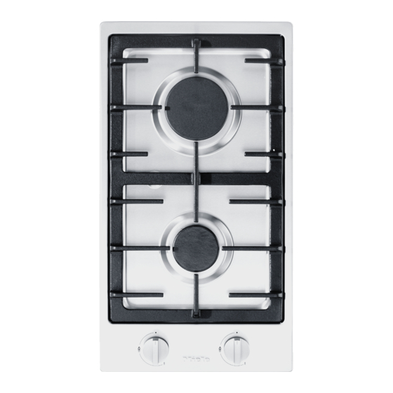
Page 17: Guide To The Appliance
Guide to the appliance a Large burner Control knobs for the burner b Normal burner e Rear c Pot rests f Front d Symbols to indicate which gas burner the control is for... -
Page 18: Control Knob
Guide to the appliance Control knob Symbol Description Burner off, the gas supply is turned off Largest flame Smallest flame... -
Page 19: Burner
Guide to the appliance Burner n Burner cap o Burner head p Thermocouple (flame failure monitor) q Ignitor r Burner base... -
Page 20: Before Using For The First Time
Before using for the first time Please stick the extra data plate for Switching on the hob for the the appliance supplied with this first time documentation in the space provided The metal components have a in the “After sales service” section of protective coating which when heated this booklet. -
Page 21: Pans
Pans - Remember when purchasing new Ø Pan [cm] pans that manufacturers usually refer Burner Minimum base to the diameter at the top of the pan diameter in their documentation, and not to the base diameter. Normal burner - You can use any cookware that is Large burner heat-resistant. -
Page 22: Tips On Saving Energy
Tips on saving energy - Use a pan lid whenever possible to minimize heat loss. - Wide, shallow pans are preferable to tall, narrow ones. They will heat up faster. - Cook with as little water as possible. - Reduce the size of the flame once the water has come to the boil or the oil is hot enough to fry in. -
Page 23: Operation
Operation Adjusting the flame Risk of fire with overheated food. Unattended food can overheat and The burners can be regulated at any catch alight. level between the strongest and weakest flame. Do not leave the hob unattended whilst it is being used. As the outer part of the flame is much hotter than the centre, the tips of the Switching on... -
Page 24: Safety Features
Safety features Thermocouple (flame failure monitor) This hob has a thermocouple. If the flame goes out, for example because food has boiled over or if there has been a sudden draught, the supply of gas to the burner will be cut off. This will prevent any gas escaping. -
Page 25: Cleaning And Care
Cleaning and care Clean the ProLine element and Danger of burning due to hot accessories after each use. surfaces. Dry the ProLine element thoroughly The hob surface, pan supports and after cleaning it with water to avoid burners will be hot after use. -
Page 26: Cleaning The Rotary Controls
Cleaning and care Cleaning the rotary controls Stainless steel trough Clean the rotary control(s) using a Risk of damage by pointed solution of warm water and a little objects. washing-up liquid applied with a soft The seal between the hob and the sponge. -
Page 27: Cleaning The Trivets
Cleaning and care The ignitor and thermocouple should Cleaning the trivets be very carefully wiped clean using a Remove the trivets. well wrung-out cloth. Clean the trivets in a dishwasher or The ignitor must not get wet, with a solution of warm water and a otherwise it will not spark. - Page 28 Cleaning and care Assembling the burners Place the burner head on the burner base so that the thermocouple and the ignitor extend through their respective holes in the burner head. The burner head must click into place correctly. Place the burner cap flat over the burner head .
-
Page 29: Problem Solving Guide
Problem solving guide Many malfunctions and faults that can occur in daily operation can be easily remedied. Time and money will be saved because a service call will not be needed. The following guide may help you to find the reason for a malfunction or a fault, and to correct it. - Page 30 The mains fuse has tripped. burner does not spark. You may need to contact a registered electrical worker or Miele. There is food residue stuck between the ignitor and the burner cap. There is food residue on the thermocouple.
-
Page 31: Optional Accessories
These products can be ordered through the Miele Webshop. Removes heavy soiling, limescale deposits and aluminium residues They can also be ordered from Miele (see end of this booklet for contact Microfibre cloth details) or from your Miele dealer. Removes finger marks and light soiling... -
Page 32: After Sales Service
You can book a Miele Customer Service Department call-out online at www.miele.com/service. Contact information for the Miele Customer Service Department can be found at the end of this document. Please quote the model identifier and serial number of your appliance (Fabr./SN/ Nr.) when contacting the Miele Customer Service Department. -
Page 33: Installation
*INSTALLATION* Installation Safety instructions for installation Risk of damage from incorrect connection. Incorrect installation can cause damage to the ProLine element. The ProLine element must only be installed by a qualified person. Damage from falling objects. Take care not to damage the ProLine element when fitting wall units or a cooker hood above it. -
Page 34: Safety Distances
*INSTALLATION* Installation Safety Distance below the appliance Safety distances There should be at least 30 mm height Safety distance above the CombiSet or plenty of space reserved below the appliance for the installation of the flexible gas connection pipe and electrical cable. It also avoids any possible hindrance towards the movement of all moveable kitchen parts (e.g. - Page 35 *INSTALLATION* Installation Safety distances to the sides and back of the appliance The ProLine elements may be installed with a wall at the rear and a tall unit or wall to one side (right or left) (see illustrations). Minimum distance between the back of the worktop cut-out and the rear edge of the worktop: Not allowed...
- Page 36 *INSTALLATION* Installation Safety distance when installing the appliance near a wall with additional niche cladding A minimum safety distance must be maintained between the worktop cut-out and any niche cladding to protect it from heat damage. If the niche cladding is made from a combustible material (e.g. wood) a minimum safety distance ...
-
Page 37: Installation Notes
*INSTALLATION* Installation Tiled worktop Installation notes Sealing between the ProLine Element and the worktop Grout lines and the hatched area underneath the ProLine element frame must be smooth and even. If they are not, the ProLine element will not sit flush with the worktop and the sealing The ProLine element and worktop strip underneath the top part of the... -
Page 38: Building-In Dimensions
*INSTALLATION* Installation Building-in dimensions All dimensions are given in mm. a Spring clamps b Front c Building-in depth d Mains connection box with mains connection cable, L = 1440 mm e Gas connection R 1/2... -
Page 39: Installing Several Proline Elements
*INSTALLATION* Installation Installing several ProLine elements Example: 3 ProLine elements a Spring clamps b Spacer bars c Gap between spacer bars and worktop d Cover e ProLine element width less 8 mm f ProLine element width g ProLine element width less 8 mm h Worktop cut-out... - Page 40 *INSTALLATION* Installation Calculating the worktop cut-out The frames of the ProLine elements overlap the worktop at the outside right and left by 8 mm on each side. Add up the widths of the ProLine elements and subtract 16 mm from this figure. Example: 288 mm + 288 mm + 380 mm = 956 mm - 16 mm = 940 mm The ProLine elements are 288 mm, 380 mm or 576 mm wide depending on the...
-
Page 41: Installation
*INSTALLATION* Installation Wooden worktops Installation Seal any cut surfaces on wooden Preparing the worktop worktops with a special varnish, Make the worktop cut-out as shown silicone sealant or resin to prevent the in “Building-in dimensions” or as wood from swelling as a result of calculated (see “Installing several moisture ingress. - Page 42 *INSTALLATION* Installation Natural stone worktops You will need heavy duty double-sided tape (not supplied) to secure the spring clamps and spacer bars. Apply silicone to the side and lower edges of the spring clamps and the spacer bars . Then fill gap between spacer bar ...
- Page 43 *INSTALLATION* Installation Fitting the ProLine element Installing several ProLine elements Feed the mains connection cable Push the built-in ProLine element to down through the cut-out. the side until the holes in the spacer bar can be seen. Starting at the front, position the ProLine appliance in the worktop cut- out.
- Page 44 *INSTALLATION* Installation Connecting the ProLine element Removing a ProLine element Connect the ProLine element/ If the ProLine element is accessible elements to the electricity supply and from below, push it upwards to to the gas supply (see “Installation – remove it.
-
Page 45: Gas Connection
*INSTALLATION* Installation Gas connection Connection to the gas supply must be carried out in strict accordance Attention! According to the Gas with current local regulations. Every Safety Ordinance of Hong Kong, any appliance should have its own easily gas installation works including the accessible isolating valve and test installation of appliances and point. - Page 46 *INSTALLATION* Installation This appliance is set up for connection to HK liquefied petroleum gas (HKLPG) or HK town gas (HKTG) (see label on the appliance). Appliances set up for connection to HK town gas have an external gas governor MDG ELITRE (model-no. EL-125, pressure setting at 10 mbar) included.
-
Page 47: Burner Ratings
*INSTALLATION* Installation Burner ratings Rated Heat Input Burner Gas type Highest Lowest setting setting Normal burner HK Liquefied Petroleum gas (29 mbar) 1.80 0.35 HK Town gas (10 mbar) 1.80 – 0.35 Large burner HK Liquefied Petroleum gas (29 mbar) 3.00 0.50 HK Town gas (10 mbar) 3.00 –... -
Page 48: Electrical Connection
If the mains connection cable is damaged, it must only be replaced with a specific mains connection cable of the same type (available from the Miele Customer Service Department). For safety reasons, such replacement may only be carried out by a qualified specialist or the Miele Customer Service Department. -
Page 49: Technical Data
Technical Data Model No CS 1013-1 Cut-out dimensions Width 272 mm Depth 500 mm Build-in depth 87 mm (Allow additional space below for connection to the gas supply) Unit Dimensions Width 288 mm Depth 520 mm Electrical connection Voltage 220–240 V Fuse rating 13 A Gas Type HK Town Gas HK Liquefied Petroleum (with external gas... - Page 51 Hong Kong, China Hong Kong, China Miele (Hong Kong) Ltd. Miele (Hong Kong) Ltd. 41/F - 4101, Manhattan Place 香港九龍灣宏泰道23號 23 Wang Tai Road Manhattan Place 41樓4101室 Kowloon Bay 電話: (852) 2610 1025 Hong Kong 傳真: (852) 3579 1404 Tel: (852) 2610 1025 電郵地址: customerservices@miele.com.hk...
- Page 52 CS 1013-1 en-HK M.-Nr. 10 829 880 / 02...