Table of Contents
Advertisement
Quick Links
Advertisement
Table of Contents

Related Manuals for akpo WK-7

Summary of Contents for akpo WK-7
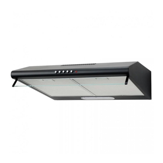
- Page 1 MANUAL KITCHEN HOOD WK-7 Manufacturer: Production and trading enterprise “AKPO” Spółka jawna 05-080 Izabelin-Laski; ul. Łąkowa 10 www.akpo.pl Production plant: 06-430 Sońsk; ul. Ciechanowska 26 phone: (0-23) 671-34-70 fax: (0-23) 671-34-72...
-
Page 2: General Information
1. GENERAL INFORMATION The hood type WK-7 is designed to remove kitchen fumes in the outlet mode (pipelines go outside the room) or in the absorption mode (internal circulation). It is designed to be installed above a gas or electric stove. It has its own lighting and exhaust turbine with a choice of one of three speeds of operation. - Page 3 2) Absorption (Fig.4b) - internal air circulation through a carbon filter (Fig. 3). Filtered air is returned through the front outlet. Carbon filters should be changed at least once every 3 months (depending on the intensity of cooking). If the hood is installed as a vent, a check valve should be installed (Fig. 2), with two folding valves that prevent the return of air from the ventilation pipe.
- Page 4 Depending on the needs, the user can use one of two options to connect the hood as a statement: 1) Outlet from the top - on the upper opening of the hood, we install a collar Ø 120 mm with a non-return valve (Fig.
- Page 5 Fig. 6 Fig. 7 Fig. 8...
- Page 6 Fig. 9 In order to connect the hood as an absorber, unscrew the curtain of the front outlet (Fig.9) and remove it from the turbine (Fig.10). Then cut the curtain with scissors (along the groove) (Fig.11 and Fig.12). The cut curtain must be placed into the hood turbine and screwed on again (Fig.13 and Fig.14).
- Page 7 Fig. 10 Fig. 11...
- Page 8 Fig. 12 Fig. 13...
- Page 9 Fig. 14 Fig. 15...
-
Page 10: Electrical Connection
2.2 ELECTRICAL CONNECTION Before connecting the hood to electricity, make sure that the voltage and frequency of the power supply correspond to the data indicated on the instrument panel. The hood must be connected to an easily accessible outlet. Removing the plug and connecting the hood directly to electricity is unacceptable. - Page 11 • Screw the cover to the inside shelf using four 3x16 screws (Fig. 20) that are attached to the kit, or drill two holes in the wall to attach the cover to the wall using the included 10x50 dowels, • If the cap will be used as an exhaust cap (Fig.
- Page 12 Fig. 19...
- Page 13 Fig. 20 Fig. 21 P3050...
- Page 14 Fig. 22 P3060 Fig. 23...
-
Page 15: Operation
4. OPERATION 4.1 CONTROL PANEL Hoods of type WK-7 are equipped with mechanical or electronic control without display. Fig. 24 Fig. 25 Fig. 26 Control (Fig. 24): A - turning the light on and off B - turbine speed I... - Page 16 A - turbine lamp B - turning the light on and off C - turbine speed I D - turbine speed II E - turbine speed III In Light, Light Plus and Light Eco hoods, work is possible after the drawer has been closed.
-
Page 17: Cleaning And Care
Turning on and off the lighting, 5. CLEANING AND CARE Regular maintenance and cleaning will ensure high performance and reliability of the hood while simultaneously prolonging its lifecycle. Pay particular attention to replacing grease filters and activated carbon filters in accordance with the manufacturer’s recommendations. - Page 18 2. Remove the grease filter 3. Remove the carbon filter, which is located inside the exhaust hood on the motor housing (P30, Fig. 29), or on both sides of it (T300, Fig. 30) rotating it counter- clockwise. 4. Then, repeating all the steps from step 3 in the reverse order, install a new filter on the turbine engine housing and turn it well to protect it against slipping.
- Page 19 5. Insert grease filters 6. Connect the hood to the electrical outlet. To replace the LED bulb (Fig. 32) proceed as follows: 1. Disconnect the hood from the electrical outlet 2. Press the bulb and turn it about 45° counter-clockwise 4.
Need help?
Do you have a question about the WK-7 and is the answer not in the manual?
Questions and answers