Table of Contents
Advertisement
Quick Links
DCS240+ Manual
Includes Instructions for:
DCS240+ Advanced Command Station Booster
2443 Transmitter Road
Panama City, Florida USA 32404
Support: helpdesk.digitrax.com
Digitrax Manuals & Instructions are updated periodically.
Please visit www.digitrax.com for the latest version of all
manuals & for available firmware updates.
Digitrax, Inc.
www.digitrax.com
C
omplete
T
rain
C
ontrol
Advertisement
Table of Contents

Related Manuals for Digitrax DCS240


Summary of Contents for Digitrax DCS240
- Page 1 DCS240+ Advanced Command Station Booster Digitrax, Inc. 2443 Transmitter Road Panama City, Florida USA 32404 Support: helpdesk.digitrax.com www.digitrax.com Digitrax Manuals & Instructions are updated periodically. Please visit www.digitrax.com for the latest version of all manuals & for available firmware updates.
-
Page 2: Table Of Contents
4.0 Customizing DCS240+, Option Switch / OPSW Setup ....14 4.1 Changing DCS240+ Option Switches ........... 14 4.2 Special Instructions for DCS240+ Op Switches 36, 37,39 and 40 .. 14 4.3 DCS240+ Option Switch Tables ..........14-16 5.0 DCS240+ Routes .................17... - Page 3 8.0 Connecting the DCS240+ to a Computer ..........19 8.1 Driver Installation................19 8.2 Hardware Installation..............19 8.3 Software Installation ...............20 8.4 Connecting the DCS240+ to a Computer Additional Troubleshooting . 20 9.0 IPL Updating the DCS240+ to the latest firmware ......20 FCC Information ..................21 Warranty and Repair Information .............22...
-
Page 4: Introduction
The Digitrax system reduces and simplifies layout wiring. The DCS240+ is an advanced CS that is intended to be used in conjunction with an existing Digitrax installation. The DCS240+ offers a number of features that make it ideal for large layouts, clubs, and modular groups who will be running many operators and trains. -
Page 5: Dcs240+ Quick Start Guide
Once you’ve completed the initial review of your DCS240+ on a test bench, you can remove your existing CS from your layout and replace it with. the DCS240+. These setup steps are broadly similar to debug steps of a DCS240+ if problems are encountered. -
Page 6: Initial Dcs240+ Testing
NO locomotives selected or consisted. The DCS240+ will beep 3 times to confirm reset has occurred. Plug a DT602 into the LocoNet “A” jack on your DCS240+.The DT602 should beep and power up. During this plug-in the red NET led should wink off several times showing the DCS240+ has seen the DT602 logon messages OK. -
Page 7: Layout Hookup Test
10. Ensure that as you increase the now active throttle speed the locomotive responds in both directions by movement on the track. 11. At this point you have proven the DCS240+ will operate properly and you can now install this on your layout. -
Page 8: Best Practice System Shut Down
If required press the DT602 PWR key at bottom left and then the TRK_ON or A-softkey. The TRACK STATUS led will light when the TRK is powered ON. By default the DCS240+ will resume in whatever state it is powered off in 2.1 Programming DCC decoders: Figure 1 and Section 1.3 detail connecting an Isolated program track for Service mode... -
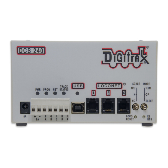
Page 9: Dcs240+ Front Panel
The screw terminals can be used with any suitable power supply up to the unit’s maximum 8 amps. The DCS240+ sets the current limit based on the active DC input. Make sure your DC power supply is rated for your desired voltage and amperage. -
Page 10: Rail B (Rb) And Rail A (Ra) Terminals
Note: The DCS240+ can only OUTPUT approximately as much voltage as it is receiv- ing. If you are only using a 15V DC power supply the DCS240+ cannot output more than 15V DCC. Use a power supply that approximates your planned track voltage. -
Page 11: Mode Switch
The DCS240+ will beep continuously as long as it is in range. When you reach a value that is out of range the DCS240+ will stop beeping. Once you decrease the trim UP or Down the DSC240 will beep again once you are in range. -
Page 12: Loco Reset Button
3.15 Easy Routes (EZ RTS) button The EZ RTS button give your simple access to setting up routes in your DCS240+. For information on setting up routes refer to the Routes in section 5.2. -
Page 13: Dcs240+ Indication Lights
3.17 DCS240+ Indication Lights The DCS240+ uses different combinations of the PWR, PROG, NET,TRACK STATUS, and USB indicators to provide information. The indicators can show what mode the DCS240+ is in as well as indicate errors and operations. Indications Meaning... -
Page 14: Customizing Dcs240+, Option Switch / Opsw Setup
See the Option Switch Table below to decide which option switches you want to change. Move the MODE toggle switch on the front of the DCS240+ into the “OP” position. The LocoNet Railsync will go inactive and all other boosters plugged in to Lo- coNet, including the one that is built into the DCS240+, will shut down. - Page 15 = Automatic advanced decoder assisted [FX] consists are enabled OPSW 17 c = Automatic advanced decoder assisted [FX] consists are disabled t = Normal DCS240+ booster short circuit shutdown time OPSW 18 c = Extended DCS240+ booster short circuit shutdown time...
- Page 16 PC to handle switch control logic t = Enable interrogate commands at power on OPSW 28 c = Disable interrogate commands at power on c= Disable DCS240+ Booster transponding OPSW 29 t = Normal route/switch output rate OPSW 31...
-
Page 17: Dcs240+ Routes
5.0 DCS240+ Routes: The DCS240+ supports up to 64 routes. Each route consists of a list that contains a TOP turnout address and its position c or t and up to 16 other turnout addresses and their positions. Routes are stored in the DCS240+’s memory and can be operated by any throt- tle in the system that can send switch commands. -
Page 18: Dt602 Reading And Editing Dcs240+ Routes
“DS7x” routes at the D soft key position. These are additional editable route choices above DCS240+ capability. Note: If there is an error with the route the DCS240+ will beep 5 times when the route is triggered. 6.0 DCS240+ Booster Operations (OPS) Mode read-back As for sec- tion 5.3, with a DT602, press the;... -
Page 19: How The Dcs240+ Manages Addresses
OPSW 15 8.0 Connecting the DCS240+ to a Computer The DCS240+ can be connected to a computer using the USB socket on the front. It provides all the same functionality as a PR3/PR4/DCS210+ and DCS52, giving you access to Digitrax SoundLoader and other computer utility programs. It can also be used as a LocoNet interface for other compatible PC layout control software. -
Page 20: Software Installation
The USB led will glow BLUE to indicate when the USB is enumerated and connected to a PC responding with proper drivers. The DCS240+ can then be accessed with PC apps by using the new COM port. You can use Windows or a utility like the free “UsbTreeView.exe” to determine which PC COM port the DCS240+ has been enumerated on. -
Page 21: Fcc Information
Other patents covering technology used by Digitrax are pending. Measures to protect trade secret information are enforced. Digitrax licenses the commercial use of LocoNet, which is trade secret technology, to other companies on a non-exclusive basis. LocoNet is copyrighted property. -
Page 22: Warranty And Repair Information
All warranties on Digitrax products are limited to repair or replacement of Digitrax products at the discretion of Digitrax. Except to the extent expressly stated, there are no warranties, express or implied, including but not limited to any warranties of merchant- ability or fitness for a particular purpose. - Page 23 © 2022 Digitrax, Inc. www.digitrax.com...
- Page 24 Need Help? Digitrax Tech Support Team Need Help?: helpdesk.digitrax.com Digitrax Tech Support Depot 24/7/365 www.digitrax.com/support Contains links to all instructions sheets and manuals, application notes, videos and tons of helpful information. Digitrax Decoder Selector www.digitrax.com/decoderselector Helps you find which decoder will fit in a particular locomotive.
Need help?
Do you have a question about the DCS240 and is the answer not in the manual?
Questions and answers