Advertisement
Advertisement

Related Manuals for NI PXIe-4190


Summary of Contents for NI PXIe-4190
- Page 1 PXIe-4190 Getting Started 2022-05-12...
-
Page 2: Table Of Contents
PXIe-4190 Getting Started........ -
Page 3: Pxie-4190 Getting Started
PXIe-4190 Getting Started PXIe-4190 Getting Started PXIe-4190 Getting Started This document explains how to install, configure, and test the PXIe-4190. Note Before you begin, install and configure your chassis and controller. Verifying the System Requirements To use the NI-DCPower instrument driver, your system must meet certain requirements. - Page 4 Store the module in the antistatic package when the module is not in use. Other Equipment There are several required items not included in your PXIe-4190 kit that you need to operate the PXIe-4190. Your application may require additional items not included in your kit to install or operate your PXIe-4190.
- Page 5 PXI Slot Blocker Kit (NI part number 199198-01) ■ Installing the Software You must be an Administrator to install NI software on your computer. 1. Install an ADE, such as LabVIEW or LabWindows™/CVI™. 2. Download the latest NI-DCPower driver software installer from ni.com/r/...
- Page 6 4. PXI Express System Timing Slot 5. PXI Express Peripheral Slot PXIe-4190 modules can be placed in PXI Express peripheral slots, PXI Express hybrid peripheral slots, or PXI Express system timing slots. 6. Touch any metal part of the chassis to discharge static electricity.
- Page 7 11. Cover all empty slots using either filler panels (standard or EMC) or slot blockers with filler panels, depending on your application. Note For more information about installing slot blockers and filler panels, go to ni.com/r/pxiblocker. 12. Power on the chassis. PXIe-4190 Pinout and LEDs © National Instruments...
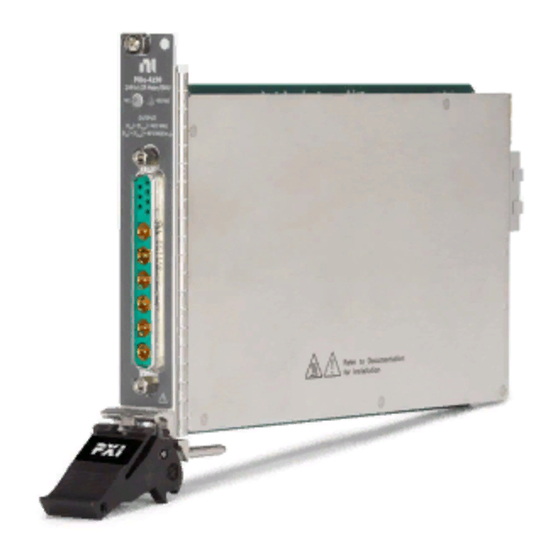
- Page 8 PXIe-4190 Getting Started PXIe-4190 2MHz LCR Meter/SMU VOLTAGE OUTPUT | + |V | = 40 V MAX ACpk | + |V | = 40 V MAX to ACpk Table 7. Item Descriptions Item Description LED Access Status Indicator LED Voltage Status Indicator...
- Page 9 PXIe-4190 Getting Started Table 2. Coaxial Contacts Descriptions Contact LCR Mode Functionality SMU Mode Functionality A1 (Center Conductor) LO CUR A1 (Outer Conductor) Isolated Shield GUARD A2 (Center Conductor) LO POT Sense HI A2 (Outer Conductor) Isolated Shield GUARD A3 (Center Conductor)
- Page 10 Configuring the PXIe-4190 in MAX Use Measurement & Automation Explorer (MAX) to configure your NI hardware. MAX informs other programs about which NI hardware products are in the system and how they are configured. MAX is automatically installed with NI-DCPower.
- Page 11 Ranges HI/LO CUR – Cabling Guidelines When using the PXIe-4190 in LCR mode or in the lower two current ■ ranges in SMU mode, you must set the niDCPower Cable Length property or NIDCPOWER_ATTR_CABLE_LENGTH attribute. For cables that breakout into BNC/Triax terminations, secure the attached ■...
- Page 12 PXIe-4190 Getting Started for the control loop being open. If the PXIe-4190 is run open loop due to accidental sense lead disconnection, allow a minimum of 1 minute after establishing proper lead connections before making measurements. Four-Terminal Pair Connections To minimize the effects of cable inductance on measurements, you must use a four- terminal pair (4TP) connection scheme to provide a low-inductance path for the return current from the excitation source to flow.
- Page 13 PXIe-4190 Getting Started 1. HI CUR 2. HI POT 3. LO POT 4. LO CUR 5. Connection between isolated shield conductors LCR Short Connection © National Instruments...
- Page 14 PXIe-4190 Getting Started 1. HI CUR 2. HI POT 3. LO POT 4. LO CUR 5. Connection between isolated shield conductors LCR Load Connection ni.com...
- Page 15 Switching DUTs 1. Set the niDCPower Output Connected or Output Enabled property to FALSE. 2. Disconnect the DUT from the PXIe-4190. 3. Reconnect the DUT to the PXIe-4190. 4. Set the niDCPower Output Connected or Output Enabled property to TRUE.
- Page 16 After first installing the PXIe-4190 in a chassis ■ After any module that is in the same chassis as the PXIe-4190 is installed, ■ uninstalled, or moved When the PXIe-4190 is in an environment where the ambient temperature ■...
- Page 17 Location Description InstrumentStudio InstrumentStudio is automatically installed When you install NI- when you install the NI-DCPower driver on a DCPower on a 64- 64-bit system. You can access InstrumentStudio bit system, you can in any of the following ways: monitor, control, and...
- Page 18 KnowledgeBase for additional information our technical support engineers create as they answer common user questions and resolve unexpected issues. What Should I Do if the PXIe-4190 Does Not Appear in MAX? 1. In the MAX configuration tree, expand Devices and Interfaces.
- Page 19 If the ACCESS LED fails to light after you power on the chassis, a problem may exist with the chassis power rails, a hardware module, or the LED. Notice Apply external signals only while the PXIe-4190 is powered on. Applying external signals while the module is powered off may cause damage.
-
Page 20: Lcr Cables
PXIe-4190 Getting Started LCR Cables SHDB13W6-4BNCM-LL Cable SHDB13W6-4BNCM-LL Cable The SHDB13W6-4BNCM-LL is a D-SUB to male BNC cable for connecting the PXIe-4190. Ø 18.39 mm #8, M4 81.35 mm (0.724 in.) (3.203 in.) 73.20 mm (2.882 in.) 40.00 mm 2x #4-40 Screw (1.575 in) -
Page 21: Shdb13W6-4Triaxm-Ll Cable
Chassis Ground Green Note Isolated Shield and GUARD are electrically equivalent and are allowed to be tied together in SMU mode. SHDB13W6-4TRIAXM-LL Cable SHDB13W6-4TriaxM-LL Cable The SHDB13W6-4TriaxM-LL is a D-SUB to Triaxial cable for connecting the PXIe-4190. © National Instruments... - Page 22 PXIe-4190 Getting Started 46.57 mm (1.833 in) 81.35 mm Ø 15.50 mm 32.00 mm (3.203 in.) (1.260 in) (0.610 in) 73.20 mm (2.882 in.) 40.00 mm 2x #4-40 Screw (1.575 in) 37.47 mm (1.475 in) SHDB13W6-4TriaxM-LL Cable Pinout PIN 1...
-
Page 23: Shdb13W6-Db13W6-Ll Cable
Note Isolated Shield and GUARD are electrically equivalent and are allowed to be tied together in SMU mode. SHDB13W6-DB13W6-LL Cable SHDB13W6-DB13W6-LL Cable The SHDB13W6-DB13W6-LL is a D-SUB to D-SUB cable for connecting the PXIe-4190. 81.35 mm (3.203 in.) Ø 18.39 mm (0.724 in.) - Page 24 PXIe-4190 Getting Started SHDB13W6-DB13W6-LL Cable Pinout PIN 5 PIN 1 PIN 1 PIN 5 Table 7. Signal Descriptions Left/Right (D-SUB) LCR Mode Functionality SMU Mode Functionality PIN 1 to PIN 7 General purpose input/output contacts A1 (Inner Conductor) LO CUR...
- Page 25 PXIe-4190 Getting Started Note Isolated Shield and GUARD are electrically equivalent and are allowed to be tied together in SMU mode. © National Instruments © 2022 National Instruments Corporation.
Need help?
Do you have a question about the PXIe-4190 and is the answer not in the manual?
Questions and answers