Table of Contents
Advertisement
Quick Links
Advertisement
Table of Contents

Related Manuals for Lenovo ThinkSystem SR250 V2


Summary of Contents for Lenovo ThinkSystem SR250 V2
- Page 1 ThinkSystem SR250 V2 Maintenance Manual Machine Types: 7D7Q and 7D7R...
- Page 2 Before using this information and the product it supports, be sure to read and understand the safety information and the safety instructions, which are available at: http://thinksystem.lenovofiles.com/help/topic/safety_documentation/pdf_files.html In addition, be sure that you are familiar with the terms and conditions of the Lenovo warranty for your server, which can be found at: http://datacentersupport.lenovo.com/warrantylookup Second Edition (April 2022) ©...
-
Page 3: Table Of Contents
Install a memory module ..Handling static-sensitive devices ..PCIe adapter replacement... 2.5-inch backplane replacement ..© Copyright Lenovo 2022... - Page 4 Index ....173 model) ....138 Complete the parts replacement ..140 ThinkSystem SR250 V2 Maintenance Manual...
-
Page 5: Safety
Vor der Installation dieses Produkts die Sicherheitshinweise lesen. Prima di installare questo prodotto, leggere le Informazioni sulla Sicurezza. Les sikkerhetsinformasjonen (Safety Information) før du installerer dette produktet. Antes de instalar este produto, leia as Informações sobre Segurança. © Copyright Lenovo 2022... -
Page 6: Safety Inspection Checklist
1 & IEC 60950-1, the standard for Safety of Electronic Equipment within the Field of Audio/Video, Information Technology and Communication Technology. Lenovo assumes you are qualified in the servicing of equipment and trained in recognizing hazards energy levels in products. Access to the equipment is by the use of a tool, lock and key, or other means of security, and is controlled by the authority responsible for the location. - Page 7 Click Power ➙ Power Cables to see all line cords. • Make sure that the insulation is not frayed or worn. 3. Check for any obvious non-Lenovo alterations. Use good judgment as to the safety of any non-Lenovo alterations.
- Page 8 ThinkSystem SR250 V2 Maintenance Manual...
-
Page 9: Chapter 1. Introduction
Chapter 1. Introduction The ThinkSystem SR250 V2 server is a 1U rack server designed for high-volume network transaction processing. This high-performance, multi-core server is ideally suited for networking environments that require superior processor performance, input/output (I/O) flexibility, and high manageability. - Page 10 Note: When M.2 drives have been installed, and the system has been set to software RAID mode in the UEFI settings, regardless if the disks are configured as an array or as separate disks, the M.2 drive cannot be used to install the Windows operating system. ThinkSystem SR250 V2 Maintenance Manual...
- Page 11 – ThinkSystem RAID 5350-8i PCIe 12Gb Adapter – ThinkSystem 4350-8i SAS/SATA 12Gb HBA Integrated functions • Lenovo XClarity Controller, which provides service processor control and monitoring functions, video controller, and remote keyboard, video, mouse, and remote drive capabilities. • Light Path Diagnostics •...
- Page 12 – Max: 1x 95W CPU, 4x 32GB DIMM, 2x HDD or SSD, 2x 450W PSU Heat output Approximate heat output: • Minimum configuration: 379.08 BTU per hour (111 watts) • Maximum configuration : 802.5 BTU per hour (235 watts) ThinkSystem SR250 V2 Maintenance Manual...
-
Page 13: Particulate Contamination
• 450-Watt power supply: 100-127 V ac /200-240 V ac, 5.8/2.9A Environment The ThinkSystem SR250 V2 complies with ASHRAE class A2 specifications. System performance may be impacted when operating temperature is outside ASHRAE A2 specification or fan failed condition. The ThinkSystem SR250 V2 is supported in the following environment: •... -
Page 14: Firmware Updates
If Lenovo determines that the levels of particulates or gases in your environment have caused damage to the device, Lenovo may condition provision of repair or replacement of devices or parts on implementation of appropriate remedial measures to mitigate such environmental contamination. - Page 15 Hat Enterprise Linux (RHEL) and SUSE Linux Enterprise Server (SLES) operating system distributions. Machine-type-specific firmware-only UXSPs are also available. Firmware updating tools See the following table to determine the best Lenovo tool to use for installing and setting up the firmware: Tool Update...
- Page 16 2. For BMC and UEFI firmware updates. • Lenovo XClarity Provisioning Manager From Lenovo XClarity Provisioning Manager, you can update the Lenovo XClarity Controller firmware, the UEFI firmware, and the Lenovo XClarity Provisioning Manager software. Note: By default, the Lenovo XClarity Provisioning Manager Graphical User Interface is displayed when you start the server and press the key specified in the on-screen instructions.
- Page 17 • Lenovo XClarity Controller If you need to install a specific update, you can use the Lenovo XClarity Controller interface for a specific server. Notes: – To perform an in-band update through Windows or Linux, the operating system driver must be installed and the Ethernet-over-USB (sometimes called LAN over USB) interface must be enabled.
-
Page 18: Tech Tips
Tech Tips Lenovo continually updates the support website with the latest tips and techniques that you can use to solve issues that your server might encounter. These Tech Tips (also called retain tips or service bulletins) provide procedures to work around issues or solve problems related to the operation of your server. -
Page 19: Power Off The Server
Power off the server The server remains in a standby state when it is connected to a power source, allowing the Lenovo XClarity Controller to respond to remote power-on requests. To remove all power from the server (power status LED off), you must disconnect all power cables. - Page 20 ThinkSystem SR250 V2 Maintenance Manual...
-
Page 21: Chapter 2. Server Components
Use the information in this section to learn about each of the components associated with your server. Identifying your server When you contact Lenovo for help, the machine type, model, and serial number information helps support technicians to identify your server and provide faster service. -
Page 22: Front View
Information web page provides additional information for parts installation and replacement videos, and error codes for server support. Figure 4. SR250 V2 QR code Front view The front view of the server varies by the model. ThinkSystem SR250 V2 Maintenance Manual... - Page 23 Front view of the server Figure 5. Four 3.5-inch simple-swap drives model front view Front operator panel VGA connector (optional) USB 2.0 connector with Lenovo XClarity Controller Four 3.5-inch simple-swap drive bays (0-3) management USB 3.2 Gen 1 connector Rack release latches Figure 6.
-
Page 24: Front Operator Panel
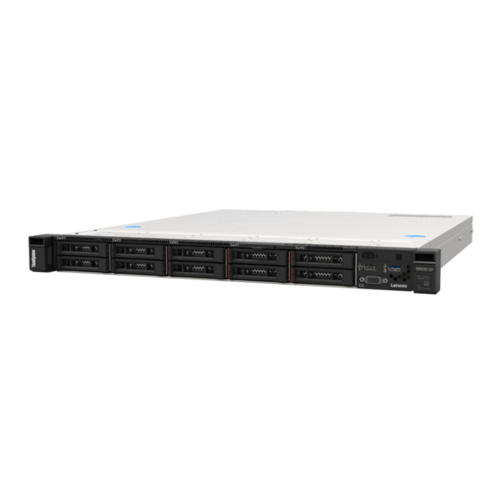
Figure 8. Eight 2.5-inch hot-swap drives model front view USB 2.0 connector with Lenovo XClarity Controller VGA connector (optional) management USB 3.2 Gen 1 connector Eight 2.5-inch hot-swap drive bays (0-7) Front operator panel Rack release latches Figure 9. Ten 2.5-inch hot-swap drives model front view Note: The last two drive bays may not be supported if only the eight-bay backplane is installed. -
Page 25: Rear View
Ethernet LAN. System ID button/LED (blue): Use this blue LED to visually locate the server among other servers. This LED is also used as a presence detection button. You can use Lenovo XClarity Administrator to light this LED remotely. - Page 26 LEDs to help you identify the Ethernet connectivity and activity. If the LOM adapter is not installed, Ethernet connector 1 can be set as Lenovo XClarity Controller Network connector. To set Ethernet connector 1 as Lenovo XClarity Controller Network connector, start Setup Utility and select BMC Settings ➙ Network Settings ➙...
-
Page 27: System-Board Switches, Jumpers, And Buttons
System-board switches, jumpers, and buttons The illustrations in this section provide information about the switches, jumpers, and buttons that are available on the system board. For more information about the LEDs that are available on the system board, see “System-board LEDs” on page System-board LEDs The following illustration indicates the light-emitting diodes (LEDs) on the system board. - Page 28 SATA connector 7 Ethernet connector 2 SATA connector 0-3 Ethernet connector 1 (shared with XCC network port) Fan 3 connector Lenovo XClarity Controller (XCC) management port SGPIO1 connector VGA and serial port connector SATA connector 5 Front VGA connector SATA connector 4...
-
Page 29: System-Board Jumpers And Buttons
Table 7. System-board connectors (continued) System power connector PCIe 4.0 x16 slot 1 to 2 SATA connector 6 PCIe 3.0 x8 slot 3 System-board jumpers and buttons The following illustration indicates the location of the jumpers and buttons on the server. Note: If there is a clear protective sticker on the top of the switch blocks, you must remove and discard it to access the switches. -
Page 30: Backplates And Backplanes
• Pins 2 and 3: Override the power-on permission. Force XCC update jumper • Pins 1 and 2: Normal (default). • Pins 2 and 3: Force the Lenovo XClarity Controller to update to the latest version. Clear CMOS jumper • Pins 1 and 2: Normal (default). - Page 31 Backplate, four 3.5-inch simple-swap drives (connects to Gen 3 RAID adapter) Figure 18. Backplate, four 3.5-inch simple-swap drives (connects to Gen 3 RAID adapter) Backplate, four 3.5-inch simple-swap drives (connects to Gen 4 RAID adapter) Figure 19. Backplate, four 3.5-inch simple-swap drives (connects to Gen 4 RAID adapter) Backplate, three 3.5-inch simple-swap drives and one NVMe drive (connects to onboard connectors) Figure 20.
-
Page 32: Pcie Riser Assembly
Backplane, eight 2.5-inch hot-swap drives Figure 22. Backplane, eight 2.5-inch hot-swap drives Backplane, ten 2.5-inch hot-swap drives Figure 23. Backplane, ten 2.5-inch hot-swap drives PCIe riser assembly Use this information to locate the connectors on the PCIe riser assembly. ThinkSystem SR250 V2 Maintenance Manual... -
Page 33: Parts List
27 Figure 27 “Server components - 3.5-inch drive model” on page http://datacentersupport.lenovo.com/us/en/products/servers/thinksystem/sr250/7Y51/parts Note: Depending on the model, your server might look slightly different from the illustration. The parts listed in the following table are identified as one of the following:... - Page 34 Tier 1 CRU at your request with no service agreement, you will be charged for the installation. • Tier 2 customer replaceable unit (CRU): You may install a Tier 2 CRU yourself or request Lenovo to install it, at no additional charge, under the type of warranty service that is designated for your server.
- Page 35 2.5-inch drive model Figure 26. Server components - 2.5-inch drive model Chapter 2 Server components...
- Page 36 For more information about ordering the parts shown in Figure 26 “Server components - 2.5-inch drive model” on page http://datacentersupport.lenovo.com/us/en/products/servers/thinksystem/sr250/7Y51/parts It is highly recommended that you check the power summary data for your server using Lenovo Capacity Planner before purchasing any new parts. Top cover √...
- Page 37 Table 11. Parts list - 2.5-inch drive model (continued) Index Description Tier 1 CRU Tier 2 CRU Consuma- ble and Structural part Heat sink √ Backplane, eight 2.5-inch hot-swap drives √ Backplane, ten 2.5-inch hot-swap drives √ Chapter 2 Server components...
- Page 38 3.5-inch drive model Figure 27. Server components - 3.5-inch drive model ThinkSystem SR250 V2 Maintenance Manual...
- Page 39 For more information about ordering the parts shown in Figure 27 “Server components - 3.5-inch drive model” on page http://datacentersupport.lenovo.com/us/en/products/servers/thinksystem/sr250/7Y51/parts It is highly recommended that you check the power summary data for your server using Lenovo Capacity Planner before purchasing any new parts. Top cover √...
- Page 40 √ Backplate, four 3.5-inch simple-swap drives √ (connects to RAID card) Backplate, four 3.5-inch simple-swap drives √ (connects to onboard connectors) Backplate, three 3.5-inch simple-swap drives and √ one NVMe drive (connects to onboard connectors) ThinkSystem SR250 V2 Maintenance Manual...
-
Page 41: Power Cords
Several power cords are available, depending on the country and region where the server is installed. To view the power cords that are available for the server: 1. Go to: http://dcsc.lenovo.com/#/ 2. Click Preconfigured Model or Configure to order. 3. Enter the machine type and model for your server to display the configurator page. - Page 42 ThinkSystem SR250 V2 Maintenance Manual...
-
Page 43: Chapter 3. Internal Cable Routing
Use the section to understand the cable routing for the front panel. Notes: ↔ ↔ ↔ ↔ • Connections between connectors; , ... • When routing the cables, ensure that all cables are routed appropriately through the cable guides and cable clips. © Copyright Lenovo 2022... - Page 44 3.5-inch model Figure 28. Front panel cable routing for 3.5-inch model ThinkSystem SR250 V2 Maintenance Manual...
-
Page 45: Fan Cable Routing
2.5-inch model Figure 29. Front panel cable routing for 2.5-inch model Front panel connector Front VGA connector Front USB 3.0/2.0 header (DCI support) Fan cable routing Use the section to understand the internal routing and connectors for fan cables. Notes: ↔... -
Page 46: Fixed Power Supply Unit Cable Routing
Use the section to understand the internal routing and connectors for the fixed power supply unit. Notes: ↔ ↔ ↔ ↔ • Connections between connectors; , ... • When routing the cables, ensure that all cables are routed appropriately through the cable guides and cable clips. ThinkSystem SR250 V2 Maintenance Manual... -
Page 47: Hot-Swap Power Supply Unit Cable Routing
Figure 31. Fixed power supply unit cable routing Processor power connector System power connector Hot-swap power supply unit cable routing Use the section to understand the internal routing and connectors for the hot-swap power supply units. Notes: ↔ ↔ ↔ ↔... -
Page 48: Flash Power Module Cable Routing
Use the section to understand the internal routing and connectors for the flash power module. Notes: ↔ ↔ ↔ ↔ • Connections between connectors; , ... • When routing the cables, ensure that all cables are routed appropriately through the cable guides and cable clips. ThinkSystem SR250 V2 Maintenance Manual... -
Page 49: Backplane And Backplate Cable Routing
Figure 33. Flash power module cable routing Flash power module Backplane and backplate cable routing Use the information in this section to route the cables for the backplates and backplanes. Four 3.5-inch simple-swap drive cable routing Use this section to understand how to route cables for four 3.5-inch simple-swap drive model. Notes: ↔... - Page 50 Four SATA drives (Software RAID) Figure 34. Four SATA drives (Software RAID) From Backplate: Power cable System board: Backplane power connector Backplate: SATA cable System board: SATA connector 0-3 ThinkSystem SR250 V2 Maintenance Manual...
- Page 51 Three SATA drives and one NVMe drive (Software RAID) Figure 35. Three SATA drives and one NVMe drive (Software RAID) From Backplate: Power cable System board: Backplane power connector Backplate: SATA cable System board: SATA connector 0-3 Backplate: NVMe cable System board: MCIO x4 connector for NVMe Chapter 3 Internal cable routing...
-
Page 52: Four 3.5-Inch Hot-Swap Drive Cable Routing
Use this section to understand how to route cables for four 3.5-inch hot-swap drive model. Notes: ↔ ↔ ↔ ↔ • Connections between connectors; , ... • When routing the cables, ensure that all cables are routed appropriately through the cable guides and cable clips. ThinkSystem SR250 V2 Maintenance Manual... - Page 53 Four SATA/SAS drives (Software RAID) Figure 37. Four SATA/SAS drives (Software RAID) From Backplane: Power connector System board: Backplane power connector Backplane: SATA signal connector System board: SATA connector 0-3 Chapter 3 Internal cable routing...
-
Page 54: Eight 2.5-Inch Hot-Swap Drive Cable Routing
Use this section to understand how to route cables for eight 2.5-inch hot-swap drive model. Notes: ↔ ↔ ↔ ↔ • Connections between connectors; , ... • When routing the cables, ensure that all cables are routed appropriately through the cable guides and cable clips. ThinkSystem SR250 V2 Maintenance Manual... - Page 55 Eight SATA/SAS drives (Software RAID) Figure 39. Eight SATA/SAS drives (Software RAID) From Backplane: Power connector System board: Backplane power connector Backplane: SATA signal connector 1 System board: SATA connector 0-3 Backplane: SATA signal connector 2 (Signal) System board: SATA connector 4/5/6/7 Backplane: SATA signal connector 2 (SGPIO) System board: SGPIO1 connector Chapter 3...
-
Page 56: Ten 2.5-Inch Hot-Swap Drive Cable Routing
Use this section to understand how to route cables for ten 2.5-inch hot-swap drive model. Notes: ↔ ↔ ↔ ↔ • Connections between connectors; , ... • When routing the cables, ensure that all cables are routed appropriately through the cable guides and cable clips. ThinkSystem SR250 V2 Maintenance Manual... - Page 57 Ten SATA/SAS drives with one 16i (Hardware RAID/HBA) From Backplane: Power connector System board: Backplane power connector Backplane: SATA signal connector 1 16i: C0 Backplane: SATA signal connector 2 16i: C1 Backplane: SATA signal connector 3 16i: C2 Figure 41. Ten SATA/SAS drives with one 16i (Hardware RAID/HBA) Chapter 3 Internal cable routing...
- Page 58 System board: Backplane power connector Backplane: SATA signal connector 1 8i: C0 Backplane: SATA signal connector 2 8i: C1 Backplane: SATA signal connector 3 8i: C0 Figure 42. Ten SATA/SAS drives with two 8i (Hardware RAID/HBA) ThinkSystem SR250 V2 Maintenance Manual...
-
Page 59: Chapter 4. Hardware Replacement Procedures
Go to to download firmware updates for your server. ThinkSystem SR250 V2 Drivers and Software Important: Some cluster solutions require specific code levels or coordinated code updates. If the component is part of a cluster solution, verify that the latest level of code is supported for the cluster solution before you update the code. -
Page 60: System Reliability Guidelines
Operating the server with a missing air baffle might damage the processor. • All processor sockets must contain either a socket cover or a processor with heat sink. ThinkSystem SR250 V2 Maintenance Manual... -
Page 61: Working Inside The Server With The Power On
• When more than one processor is installed, fan population rules for each server must be strictly followed. Working inside the server with the power on You might need to keep the power on with the server cover removed to look at system information on the display panel or to replace hot-swap components. -
Page 62: Install The 2.5-Inch Backplane
If you are instructed to return the component or optional device, follow all packaging instructions, and use any packaging materials for shipping that are supplied to you. Install the 2.5-inch backplane Use this information to install the 2.5-inch backplane. About this task ThinkSystem SR250 V2 Maintenance Manual... -
Page 63: Bay
Attention: • Read the following section(s) to ensure that you work safely. – “Safety” on page iii – “Installation Guidelines” on page 51 Note: Depending on the configuration, the following illustration might differ slightly from your backplane. Watch the procedure A video of this procedure is available at YouTube: https://www.youtube.com/playlist?list=PLYV5R7hVcs- BPZOAqQMD37KjuxaVHVBkH... -
Page 64: Remove A 2.5-Inch Drive From A 3.5-Inch Drive
Figure 45. Removing the screws that secure the 2.5-inch drive and the drive adapter Step 3. Remove the two screws that secure the 2.5-inch drive; then, lift the drive up to remove it from the drive adapter. ThinkSystem SR250 V2 Maintenance Manual... -
Page 65: Install A 2.5-Inch Drive Into A 3.5-Inch Drive
“Front view” on page • The drives in a single RAID array must be the same type, same size, and same capacity. • For a complete list of supported optional devices for the server, see https://static.lenovo.com/us/en/ serverproven/index.shtml Watch the procedure... - Page 66 2. Complete the parts replacement. See “Complete the parts replacement” on page 140. 3. Check the drive activity LED on the front operator panel to verify if the drives are operating correctly. See “Front operator panel” on page 16 ThinkSystem SR250 V2 Maintenance Manual...
-
Page 67: 3.5-Inch Backplane Replacement
4. If you are instructed to return the component or optional device, follow all packaging instructions, and use any packaging materials for shipping that are supplied to you. 3.5-inch backplane replacement Use the following information to remove and install the 3.5-inch backplane. Remove the 3.5-inch backplane Use this information to remove the 3.5-inch drive backplane. -
Page 68: Install The 3.5-Inch Backplane
Insert the backplane into the chassis at an angle. Make sure the pins are against the backplane on the backside. Rotate the backplane up towards the front of the server. Close the retaining clips to secure the backplane in place. ThinkSystem SR250 V2 Maintenance Manual... -
Page 69: 3.5-Inch Backplate Replacement
Figure 50. 3.5-inch backplane installation After you finish 1. Connect the cables to the backplane. See “Backplane and backplate cable routing” on page 2. Install the top cover. See “Install the top cover” on page 134. 3. Install all drives and drive fillers into the drive bays. See “Install a hot-swap drive”... -
Page 70: Install The 3.5-Inch Backplate
• Read the following section(s) to ensure that you work safely. – “Safety” on page iii – “Installation Guidelines” on page 51 • Depending on the configuration, the following illustration might differ slightly from your backplate. Watch the procedure ThinkSystem SR250 V2 Maintenance Manual... -
Page 71: Air Baffle Replacement
A video of this procedure is available at YouTube: https://www.youtube.com/playlist?list=PLYV5R7hVcs- BPZOAqQMD37KjuxaVHVBkH Procedure Step 1. Install the backplate. Insert the backplate into the chassis at an angle. Make sure the pins are against the backplate on the backside. Rotate the backplate up towards the front of the server. Close the retaining clips to secure the backplate in place. -
Page 72: Install The Air Baffle
Install the air baffle Use this information to install the air baffle. About this task Attention: • Read the following section(s) to ensure that you work safely. – “Safety” on page iii ThinkSystem SR250 V2 Maintenance Manual... -
Page 73: Cmos Battery (Cr2032) Replacement
– “Installation Guidelines” on page 51 • For proper cooling and airflow, reinstall the air baffle before you turn on the server. Operating the server with the air baffle removed might damage server components. Watch the procedure A video of this procedure is available at YouTube: https://www.youtube.com/playlist?list=PLYV5R7hVcs- BPZOAqQMD37KjuxaVHVBkH Procedure... - Page 74 The following notes describe information that you must consider when replacing the battery. • Lenovo has designed this product with your safety in mind. The lithium battery must be handled correctly to avoid possible danger. If you replace the battery, you must adhere to the following instructions.
-
Page 75: Install The Cmos Battery (Cr2032)
of charge by the manufacturer, distributor, or representative, to be recycled or disposed of in a proper manner. • After you replace the battery, you must reconfigure the solution and reset the system date and time. Watch the procedure A video of this procedure is available at YouTube: https://www.youtube.com/playlist?list=PLYV5R7hVcs- BPZOAqQMD37KjuxaVHVBkH Procedure... - Page 76 S004 CAUTION: When replacing the lithium battery, use only Lenovo specified part number or an equivalent type battery recommended by the manufacturer. If your system has a module containing a lithium battery, replace it only with the same module type made by the same manufacturer. The battery contains lithium and can explode if not properly used, handled, or disposed of.
-
Page 77: Drive Replacement
Procedure Step 1. Install the CMOS battery. Figure 56. CMOS battery installation Pivot the CMOS battery to insert it into the socket, with positive (+) side faces up. Press the battery straight down until it clicks in place. After you finish 1. -
Page 78: Install A Simple-Swap Drive
• To avoid damage to the drive connectors, make sure that the server top cover is in place and fully closed whenever you install or remove a drive. ThinkSystem SR250 V2 Maintenance Manual... - Page 79 “Front view” on page • The drives in a single RAID array must be the same type, same size, and same capacity. • For a complete list of supported optional devices for the server, see https://static.lenovo.com/us/en/ serverproven/index.shtml Watch the procedure A video of this procedure is available at YouTube: https://www.youtube.com/playlist?list=PLYV5R7hVcs-...
-
Page 80: Remove A Hot-Swap Drive
BPZOAqQMD37KjuxaVHVBkH Procedure Step 1. Remove the hot-swap drive. Note: Install a drive bay filler or replacement drive as soon as possible. See “Install a hot-swap drive” on page Figure 59. 2.5-inch hot-swap drive removal ThinkSystem SR250 V2 Maintenance Manual... -
Page 81: Install A Hot-Swap Drive
“Front view” on page • The drives in a single RAID array must be the same type, same size, and same capacity. • For a complete list of supported optional devices for the server, see https://static.lenovo.com/us/en/ serverproven/index.shtml Chapter 4 Hardware replacement procedures... -
Page 82: Fan Replacement
4. If you are instructed to return the component or optional device, follow all packaging instructions, and use any packaging materials for shipping that are supplied to you. Fan replacement Use the following information to remove and install the fan. ThinkSystem SR250 V2 Maintenance Manual... -
Page 83: Remove A Fan
Remove a fan Use this information to remove a fan. About this task S002 CAUTION: The power-control button on the device and the power switch on the power supply do not turn off the electrical current supplied to the device. The device also might have more than one power cord. To remove all electrical current from the device, ensure that all power cords are disconnected from the power source. -
Page 84: Install A Fan
2. If you are instructed to return the component or optional device, follow all packaging instructions, and use any packaging materials for shipping that are supplied to you. Install a fan Use this information to install a fan. About this task S002 ThinkSystem SR250 V2 Maintenance Manual... - Page 85 CAUTION: The power-control button on the device and the power switch on the power supply do not turn off the electrical current supplied to the device. The device also might have more than one power cord. To remove all electrical current from the device, ensure that all power cords are disconnected from the power source.
-
Page 86: Flash Power Module Replacement
140. Flash power module replacement Use the following information to remove and install the flash power module Remove the flash power module Use this information to remove the flash power module. About this task S002 ThinkSystem SR250 V2 Maintenance Manual... - Page 87 CAUTION: The power-control button on the device and the power switch on the power supply do not turn off the electrical current supplied to the device. The device also might have more than one power cord. To remove all electrical current from the device, ensure that all power cords are disconnected from the power source.
-
Page 88: Install The Flash Power Module
• If the server is installed in a rack, remove the server from the rack. • To avoid possible danger, read and follow the following safety information. Watch the procedure A video of this procedure is available at YouTube: https://www.youtube.com/playlist?list=PLYV5R7hVcs- BPZOAqQMD37KjuxaVHVBkH Step 1. Install the flash power module. ThinkSystem SR250 V2 Maintenance Manual... -
Page 89: Front Operator Panel Replacement
Figure 66. Flash power module installation Insert the end of the flash power module into its carrier. Rotate the flash power module down into the carrier until the tab clicks in place to secure it. After you finish 1. Connect the flash power module cable to the RAID adapter. See “Flash power module cable routing”... -
Page 90: Install The Front Operator Panel (2.5-Inch Drive Model)
Use this information to install the front operator panel (2.5-inch drive model). About this task Attention: Read the following section(s) to ensure that you work safely. • “Safety” on page iii • “Installation Guidelines” on page 51 Watch the procedure ThinkSystem SR250 V2 Maintenance Manual... -
Page 91: Remove The Front Operator Panel
A video of this procedure is available at YouTube: https://www.youtube.com/playlist?list=PLYV5R7hVcs- BPZOAqQMD37KjuxaVHVBkH Procedure Step 1. Slide the front operator panel into the assembly bay. Figure 69. Front operator panel (2.5-inch drive model) installation Step 2. Install the two screws to secure the front operator panel. Figure 70. - Page 92 Step 2. Remove the two screws that secure the front operator panel. Figure 71. Front operator panel removal Step 3. Pull out the front operator panel from the server. Figure 72. Front operator panel removal ThinkSystem SR250 V2 Maintenance Manual...
-
Page 93: Install The Front Operator Panel (3.5-Inch Drive Model)
After you finish If you are instructed to return the component or optional device, follow all packaging instructions, and use any packaging materials for shipping that are supplied to you. Install the front operator panel (3.5-inch drive model) Use this information to install the front operator panel (3.5-inch drive model). About this task Attention: Read the following section(s) to ensure that you work safely. -
Page 94: Heat Sink Replacement
BPZOAqQMD37KjuxaVHVBkH Procedure Step 1. Remove the top cover. See “Remove the top cover” on page 132. Step 2. Loosen screw 1 and 2: Partially loosen screw 1. Fully loosen screw 2. Fully loosen screw 1. ThinkSystem SR250 V2 Maintenance Manual... -
Page 95: Install The Heat Sink
Notes: 1. Gently remove the four screws to avoid any possible damage to the system board. 2. Always keep the four screws attached to the heat sink. 3. Do not touch the thermal grease while handling the heat sink. Step 3. Loosen screw 3 and 4: Partially loosen screw 3. - Page 96 Step 3. Tighten screw 3 and 4: Partially tighten screw 3. Fully tighten screw 4. Fully tighten screw 3. After you finish 1. Install the top cover. See “Install the top cover” on page 134. ThinkSystem SR250 V2 Maintenance Manual...
-
Page 97: Memory Module Replacement
2. Complete the parts replacement. See “Complete the parts replacement” on page 140. Memory module replacement Use the following information to remove and install a memory module. Remove a memory module Use this information to remove a memory module. About this task Attention: •... - Page 98 • If necessary, you can use a pointed tool to open the retaining clips due to space constraints. Pencils are not recommended as a tool as they may not be strong enough. Place the tip of the tool in the recess on the top of the retaining clip. ThinkSystem SR250 V2 Maintenance Manual...
-
Page 99: Install A Memory Module
Carefully rotate the retaining clip away from the memory module slot. Step 4. Remove the memory module. Figure 79. Memory module removal Make sure that both retaining clips are in the fully-open position. Grasp the memory module at both ends and carefully lift it out of the slot. After you finish 1. - Page 100 Procedure Step 1. Locate the memory module slot on the system board. Note: Ensure that you observe the installation rules and sequence in “Technical rules for memory modules” in the ThinkSystem SR250 V2 Setup Guide. ThinkSystem SR250 V2 Maintenance Manual...
- Page 101 Memory module slots Figure 80. Memory module slots location Step 2. Open the retaining clips outward on each end of the memory module slot. Figure 81. Opening retaining clips Attention: • To avoid breaking the retaining clips or damaging the memory module slots, handle the clips gently.
-
Page 102: Pcie Adapter Replacement
• Power off the server and peripheral devices and disconnect the power cords and all external cables. See “Power off the server” on page • If the server is installed in a rack, remove the server from the rack. ThinkSystem SR250 V2 Maintenance Manual... -
Page 103: Install A Pcie Adapter (Riser)
Watch the procedure A video of this procedure is available at YouTube: https://www.youtube.com/playlist?list=PLYV5R7hVcs- BPZOAqQMD37KjuxaVHVBkH Procedure Step 1. Make preparations for this task. Remove the top cover. See “Remove the top cover” on page 132. Remove the PCIe riser assembly. See “Remove the PCIe riser assembly”... - Page 104 Step 3. Install the PCIe adapter. Note: Ensure that you observe the installation rules and sequence in “Technical rules for PCIe adapters” in the ThinkSystem SR250 V2 Setup Guide. Figure 84. PCIe adapter installation Notes: • For the detail connectors on the PCIe riser card, see “PCIe riser assembly”...
-
Page 105: Remove The Pcie Adapter (Slot 3)
1. Install the PCIe riser assembly. See “Install the PCIe riser assembly” on page 101. 2. Install the top cover. See “Install the top cover” on page 134. 3. If necessary, configure the RAID array using the Setup utility configuration. 4. -
Page 106: Install The Pcie Adapter (Slot 3)
RAID adapter or M.2 boot adapter in the PCIe riser assembly. • The following illustration might differ slightly from your hardware, but the installation method is the same Watch the procedure ThinkSystem SR250 V2 Maintenance Manual... -
Page 107: Pcie Riser Assembly Replacement
Install the PCIe adapter. Note: Ensure that you observe the installation rules and sequence in “Technical rules for PCIe adapters” in the ThinkSystem SR250 V2 Setup Guide. Figure 86. PCIe adapter installation Lower the PCIe adapter into the server; then, firmly press it into the connector. - Page 108 If you need to disassemble the PCIe riser assembly for recycle, remove the two screws and carefully pull the PCIe riser card out of the riser cage. Attention: You can only disassemble the PCIe riser assembly for recycle. Do not disassemble it for any other purposes. ThinkSystem SR250 V2 Maintenance Manual...
-
Page 109: Install The Pcie Riser Assembly
Figure 88. PCIe riser card removal Install the PCIe riser assembly Use this information to install the PCIe riser assembly. About this task Attention: Read the following section(s) to ensure that you work safely. • “Safety” on page iii • “Installation Guidelines”... -
Page 110: Power Supply Unit Replacement
The device also might have more than one power cord. To remove all electrical current from the device, ensure that all power cords are disconnected from the power source. S035 ThinkSystem SR250 V2 Maintenance Manual... - Page 111 CAUTION: Never remove the cover on a power supply or any part that has this label attached. Hazardous voltage, current, and energy levels are present inside any component that has this label attached. There are no serviceable parts inside these components. If you suspect a problem with one of these parts, contact a service technician.
-
Page 112: Install The Fixed Power Supply Unit
There are no serviceable parts inside these components. If you suspect a problem with one of these parts, contact a service technician. ThinkSystem SR250 V2 Maintenance Manual... -
Page 113: Remove A Hot-Swap Power Supply Unit
Attention: • Read the following section(s) to ensure that you work safely. – “Safety” on page iii – “Installation Guidelines” on page 51 • Touch the static-protective package that contains the component to any unpainted metal surface on the server; then, remove it from the package and place it on a static-protective surface. Watch the procedure A video of this procedure is available at YouTube: https://www.youtube.com/playlist?list=PLYV5R7hVcs-... - Page 114 Attention: Read the following section(s) to ensure that you work safely. • “Safety” on page iii • “Installation Guidelines” on page 51 Watch the procedure A video of this procedure is available at YouTube: https://www.youtube.com/playlist?list=PLYV5R7hVcs- BPZOAqQMD37KjuxaVHVBkH ThinkSystem SR250 V2 Maintenance Manual...
-
Page 115: Install A Hot-Swap Power Supply Unit
Procedure Step 1. Locate the hot-swap power supply in the rear of your server and disconnect the power cord from the power supply. Step 2. Remove the hot-swap power supply unit. Figure 92. Hot-swap power supply unit Press the release tab towards the handle. Carefully pull the handle to slide the hot-swap power supply unit out of the chassis. - Page 116 • Touch the static-protective package that contains the component to any unpainted metal surface on the server; then, remove it from the package and place it on a static-protective surface. Watch the procedure A video of this procedure is available at YouTube: https://www.youtube.com/playlist?list=PLYV5R7hVcs- BPZOAqQMD37KjuxaVHVBkH Procedure ThinkSystem SR250 V2 Maintenance Manual...
-
Page 117: Power Distribution Board Replacement
Step 1. Remove the power supply filler if necessary. Step 2. Align the power supply unit with the bay; then, slide the power supply unit into the bay until it snaps into position. Figure 93. Hot-swap power supply unit installation After you finish 1. - Page 118 Carefully slide the power distribution board cover forward and lift it out of the server. Figure 95. Power distribution board cover removal Step 4. Disconnect the cables from the power distribution board. See “Hot-swap power supply unit cable routing” on page ThinkSystem SR250 V2 Maintenance Manual...
-
Page 119: Install The Power Distribution Board
Step 5. Remove the two screws on the power distribution board. Figure 96. Power distribution board screw removal Step 6. Carefully slide the power distribution board backwards and remove it out of the server. Figure 97. Power distribution board removal After you finish If you are instructed to return the component or optional device, follow all packaging instructions, and use any packaging materials for shipping that are supplied to you. - Page 120 “Hot-swap power supply unit cable routing” on page Step 4. Align the power distribution board cover pin with the hook and lower it into the server; then, slightly slide the power distribution board cover backwards to insert it. ThinkSystem SR250 V2 Maintenance Manual...
- Page 121 Figure 100. Power distribution board cover installation Step 5. Fasten the two screws to secure the power distribution board cover. Figure 101. Cover screw installation After you finish 1. Install the flash power module. See “Install the flash power module” on page 2.
-
Page 122: Processor Replacement
Remove the top cover. See “Remove the top cover” on page 132. Remove the air baffle. See “Remove the air baffle” on page Remove the heat sink. See “Remove the heat sink” on page Step 2. Remove the processor. ThinkSystem SR250 V2 Maintenance Manual... -
Page 123: Install The Processor
Figure 102. Opening the processor retainer Gently pull the handle away from the processor retainer. Lift the handle along with the retainer to the fully open position. Hold the processor by both sides and gently lift it away from the processor socket. Notes: 1. - Page 124 2. Align the small triangle of the processor to the beveled corner on the socket. Then, gently lower the processor evenly into the socket. ThinkSystem SR250 V2 Maintenance Manual...
-
Page 125: Rack Latches Replacement
Figure 104. Installing the processor Step 3. Close the processor retainer, and push the handle to the locked position. Figure 105. Closing the processor retainer After you finish 1. Reinstall the heat sink. See “Install the heat sink” on page 2. - Page 126 Figure 106. ID label removal Step 3. Remove the two screws on the side of the server that secure the rack latch. Figure 107. Rack latches removal Step 4. Slide the latch backwards and remove it from the server. ThinkSystem SR250 V2 Maintenance Manual...
-
Page 127: Install The Rack Latches
Figure 108. Rack latches removal Step 5. Remove the other rack latch if necessary. After you finish If you are instructed to return the component or optional device, follow all packaging instructions, and use any packaging materials for shipping that are supplied to you. Install the rack latches Use this information to install the rack latches. - Page 128 Install the ID label to the right rack latch by inserting the label onto the right rack latch. Figure 111. ID label installation Step 4. If you are installing the other rack latch, do so now. After you finish ThinkSystem SR250 V2 Maintenance Manual...
-
Page 129: Security Bezel Replacement
1. Install the security bezel. See “Install the security bezel” on page 122. 2. Complete the parts replacement. See “Complete the parts replacement” on page 140. Security bezel replacement Use this procedure to remove or install the security bezel. Remove the security bezel Use this information to remove the security bezel. -
Page 130: Install The Security Bezel
Figure 114. Security bezel installation Step 2. Use the key to lock the security bezel to the closed position. Figure 115. Locking the security bezel After you finish ThinkSystem SR250 V2 Maintenance Manual... -
Page 131: System Board Replacement
Universally Unique Identifier, and asset tag of the server. • Use the Lenovo XClarity Essentials OneCLI to save the system configuration to external media. • Save the system-event log to external media. - Page 132 • For reference, the torque which is required for the screws to be fully tightened or removed is 5.0 +/- 0.5 lb-in. Step 3. Slightly lift up the front side of the system board; then, slide the system board towards the front of the server and lift it out of the server. ThinkSystem SR250 V2 Maintenance Manual...
-
Page 133: Install The System Board
Figure 117. System board removal After you finish Important: Before you return the system board, make sure that you install the processor socket covers from the new system board. To replace a processor socket cover: 1. Insert the new system board into the chassis. See “Install the system board”... - Page 134 Place the system board flat into the chassis. Match screw slots on the system board to the corresponding slots on the chassis. Figure 118. System board installation Step 2. Install all eight screws to secure the system board to the chassis according to the installation orders as shown. ThinkSystem SR250 V2 Maintenance Manual...
- Page 135 Figure 119. System-board screws location Notes: • The order and locations of screws installation : the lower left side near front USB 3.0 / 2.0 header the upper right side near NMI button the upper left side near the CMOS battery the lower right side between the SATA connectors and the system power connector...
-
Page 136: Update The Machine Type And Serial
13. Update the machine type and serial number with new vital product data (VPD). Use the Lenovo XClarity Provisioning Manager to update the machine type and serial number. See “Update the machine type and serial number” on page 128. 14. Enable TPM. See “Enable TPM”... - Page 137 SYSTEM_PROD_DATA.SysInfoProdName <m/t_model> −−bmc xcc_user_id:xcc_password@xcc_external_ip onecli config set SYSTEM_PROD_DATA.SysInfoSerialNum <s/n> −−bmc xcc_user_id:xcc_password@xcc_external_ip 4. Reset the Lenovo XClarity Controller to the factory defaults. See “Resetting the BMC to Factory Default” section in the XCC documentation compatible with your server at https:// sysmgt.lenovofiles.com/help/topic/lxcc_frontend/lxcc_overview.html...
-
Page 138: Enable Tpm
Note: Although the setting undefined is available as a policy setting, it should not be used. • From Lenovo XClarity Essentials OneCLI Note: Please note that a Local IPMI user and password must be setup in Lenovo XClarity Controller for remote accessing to the target system. - Page 139 OneCli.exe config set imm.TpmTcmPolicy "NationZTPM20Only" --override --imm <userid>:<password>@<ip_ address> – For customers outside Chinese Mainland that require to enable TPM: OneCli.exe config set imm.TpmTcmPolicy "TpmOnly" --override --imm <userid>:<password>@<ip_address> 3. Issue reset command to reset system: OneCli.exe misc ospower reboot --imm <userid>:<password>@<ip_address> 4.
-
Page 140: Enable Uefi Secure Boot
To enable UEFI Secure Boot from Lenovo XClarity Provisioning Manager: 1. Start the server and press the key specified in the on-screen instructions to display the Lenovo XClarity Provisioning Manager interface. (For more information, see the “Startup” section in the LXPM documentation compatible with your server at https://sysmgt.lenovofiles.com/help/topic/lxpm_frontend/... - Page 141 CAUTION: Hazardous voltage, current, and energy levels might be present. Only a qualified service technician is authorized to remove the covers where the label is attached. S033 CAUTION: Hazardous energy present. Voltages with hazardous energy might cause heating when shorted with metal, which might result in spattered metal, burns, or both.
-
Page 142: Install The Top Cover
Align the posts inside the top cover with the slots on the chassis. Step 2. Hold the front of the server and slide the top cover towards the front of the server until it clicks into place. ThinkSystem SR250 V2 Maintenance Manual... -
Page 143: Vga Cable Replacement
Figure 121. Top cover installation After you finish Complete the parts replacement. See “Complete the parts replacement” on page 140. VGA cable replacement Use the following information to remove and install the VGA cable. Remove the VGA cable (2.5-inch drive model) Use this information to remove the VGA cable for the 2.5-inch drive model. -
Page 144: Install The Vga Cable (2.5-Inch Drive Model)
• If the server is installed in a rack, remove the server from the rack. Watch the procedure A video of this procedure is available at YouTube: https://www.youtube.com/playlist?list=PLYV5R7hVcs- BPZOAqQMD37KjuxaVHVBkH Procedure Step 1. Install the VGA cable. ThinkSystem SR250 V2 Maintenance Manual... -
Page 145: Remove The Vga Cable (3.5-Inch Drive Model)
Figure 123. VGA cable installation Insert the VGA cable into the front I/O assembly. Install and fasten two screws to secure the VGA cable. After you finish 1. Install the front operator panel (2.5-inch drive model). See “Install the front operator panel (2.5-inch drive model)”... -
Page 146: Install The Vga Cable (3.5-Inch Drive Model)
If you are instructed to return the component or optional device, follow all packaging instructions, and use any packaging materials for shipping that are supplied to you. Install the VGA cable (3.5-inch drive model) Use this information to install the VGA cable for the 3.5-inch drive model. ThinkSystem SR250 V2 Maintenance Manual... - Page 147 About this task Attention: • Read the following section(s) to ensure that you work safely. – “Safety” on page iii – “Installation Guidelines” on page 51 • Turn off the server. Disconnect the power cords and all external cables. See “Power off the server”...
-
Page 148: Complete The Parts Replacement
“Firmware updates” on page • Update the UEFI configuration. • Reconfigure the disk arrays if you have installed or removed a hot-swap drive or a RAID adapter. See the Lenovo XClarity Provisioning Manager User Guide, which is available for download at: http:// datacentersupport.lenovo.com... -
Page 149: Chapter 5. Problem Determination
An alert is a message or other indication that signals an event or an impending event. Alerts are generated by the Lenovo XClarity Controller or by UEFI in the servers. These alerts are stored in the Lenovo XClarity Controller Event Log. If the server is managed by the Chassis Management Module 2 or by the Lenovo XClarity Administrator, alerts are automatically forwarded to those management applications. - Page 150 Lenovo XClarity Controller event log The Lenovo XClarity Controller monitors the physical state of the server and its components using sensors that measure internal physical variables such as temperature, power-supply voltages, fan speeds, and component status. The Lenovo XClarity Controller provides various interfaces to systems management software and to system administrators and users to enable remote management and control of a server.
-
Page 151: The Front Operator Panel And Error Leds
“Viewing Event Logs” section in the XCC documentation compatible with your server at https:// sysmgt.lenovofiles.com/help/topic/lxcc_frontend/lxcc_overview.html The front operator panel and error LEDs The front operator panel is a system of LEDs on various external and internal components of the server that leads you to the failed component. -
Page 152: Power Supply Leds
System ID button/LED (blue): Use this blue LED to visually locate the server among other servers. This LED is also used as a presence detection button. You can use Lenovo XClarity Administrator to light this LED remotely. System-error LED (yellow): When this yellow LED is lit, it indicates that a system error has occurred. A system-error LED is also on the rear of the server. -
Page 153: System-Board Leds
Table 16. 450 watts Power supply LED Description Power output LED • Green: The server is on and the power supply is working normally. (green) • Blinking green: The power supply is in zero-output mode (standby). When the server power load is low, one of the installed power supplies enters into the standby state while the other one delivers entire load. -
Page 154: General Problem Determination Procedures
• Any external devices. • Surge-suppressor device (on the server). • Printer, mouse, and non-Lenovo devices. • Each adapter. • Hard disk drives. • Memory modules until you reach the minimum configuration that is supported for the server. -
Page 155: Resolving Suspected Ethernet Controller Problems
1. Check the event log of the application that is managing the server and follow the suggested actions to resolve any event codes. • If you are managing the server from the Lenovo XClarity Administrator, begin with the Lenovo XClarity Administrator event log. -
Page 156: Power On And Power Off Problems
3. If the power button LED didn't lit on or flash correctly, Please reseat all the power supplies and make sure AC LED on PSU rear side are lit on. 4. If you have just installed an optional device, remove it, and restart the server. ThinkSystem SR250 V2 Maintenance Manual... -
Page 157: Memory Problems
6. If everything is still done and the issue cannot be resolved, please collect the failure information with system logs captured to Lenovo support. Server does not power on Complete the following steps until the problem is resolved: 1. -
Page 158: Hard Disk Drive Problems
3. Reseat the module that is displayed as “disabled,” and reboot the system. 4. If the problem persists, replace the memory module. Hard disk drive problems Use this information to resolve issues related to the hard disk drives. ThinkSystem SR250 V2 Maintenance Manual... - Page 159 • “Server cannot recognize a hard drive” on page 151 • “Multiple hard drives fail” on page 152 • “Multiple hard drives are offline” on page 152 • “A replacement hard disk drive does not rebuild” on page 152 • “Green hard disk drive activity LED does not represent actual state of associated drive”...
-
Page 160: Monitor And Video Problems
Multiple hard drives fail Complete the following steps until the problem is solved: • View the Lenovo XClarity Controller event log for events related to power supplies or vibration issues and resolve those events. • Make sure that the device drivers and firmware for the hard disk drive and server are at the latest level Important: Some cluster solutions require specific code levels or coordinated code updates. - Page 161 To use the management controller remote presence function, remove the optional video adapter. 3. If the server is installed with the graphical adapters while turning on the server, the Lenovo logo is displayed on the screen after approximately 3 minutes. This is normal operation while the system loads.
-
Page 162: Keyboard, Mouse, Kvm Switch Or Usb-Device
3. Replace the mouse. KVM switch problems 1. Make sure that the KVM switch is supported by your server. 2. Make sure that the KVM switch is powered on correctly. ThinkSystem SR250 V2 Maintenance Manual... -
Page 163: Optional-Device Problems
“PCIe adapter is not recognized or is not functioning” on page 155 • “A Lenovo optional device that worked previously does not work now” on page 156 • “A Lenovo optional device that was just installed does not work.” on page 156 •... - Page 164 9. DC cycle the system and ensure the system is enter UEFI boot menu or the operating system; then, capture the FFDC log. 10. Contact Lenovo technical support. A Lenovo optional device that was just installed does not work. 1. Make sure that: • The device is supported for the server (see https://static.lenovo.com/us/en/serverproven/index.shtml...
-
Page 165: Serial-Device Problems
6. Replace the failing device. Serial-device problems Use this information to solve problems with serial ports or devices. • “Number of displayed serial ports is less than the number of installed serial ports” on page 157 • “Serial device does not work” on page 157 Number of displayed serial ports is less than the number of installed serial ports Complete the following steps until the problem is solved. -
Page 166: Power Problems
141 for information about viewing the event log. If you are using Linux base operating system, then capture all logs back to Lenovo support for further investigation. Power problems Use this information to resolve issues related to power. -
Page 167: Network Problems
3. Make sure that the power supply AC source is stable within the supported range. 4. Swap the power supply to see if the issue follows the power supply, if it follows the power supply, then replace the failing one. 5. - Page 168 If the system hangs during the UEFI boot process with the message UEFI: DXE INIT on the display, make sure that Option ROMs were not configured with a setting of Legacy. You can remotely view the current settings for Option ROMs by running the following command using the Lenovo XClarity Essentials OneCLI: onecli config show EnableDisableAdapterOptionROMSupport --bmc xcc_userid:xcc_password@xcc_ipaddress...
- Page 169 Complete the following steps until the problem is solved. 1. An unusual smell might be coming from newly installed equipment. 2. If the problem remains, contact Lenovo Support. Server seems to be running hot Complete the following steps until the problem is solved.
-
Page 170: Software Problems
2. If you receive any error messages while you use the software, see the information that comes with the software for a description of the messages and suggested solutions to the problem. 3. Contact your place of purchase of the software. ThinkSystem SR250 V2 Maintenance Manual... -
Page 171: Appendix A. Hardware Disassembling For Recycle
Step 18. Remove the heat sink. See “Remove the heat sink” on page Step 19. Remove the processor. See “Remove the processor” on page 114. Step 20. Remove the system board. See “Remove the system board” on page 123. © Copyright Lenovo 2022... - Page 172 After disassembling the server, recycle the unit in compliance with local regulations. ThinkSystem SR250 V2 Maintenance Manual...
-
Page 173: Appendix B. Getting Help And Technical Assistance
Appendix B. Getting help and technical assistance If you need help, service, or technical assistance or just want more information about Lenovo products, you will find a wide variety of sources available from Lenovo to assist you. On the World Wide Web, up-to-date information about Lenovo systems, optional devices, services, and support are available at: http://datacentersupport.lenovo.com... -
Page 174: Collecting Service Data
Collecting service data To clearly identify the root cause of a server issue or at the request of Lenovo Support, you might need collect service data that can be used for further analysis. Service data includes information such as event logs and hardware inventory. -
Page 175: Contacting Support
• Lenovo XClarity Essentials OneCLI Lenovo XClarity Essentials OneCLI has inventory application to collect service data. It can run both in- band and out-of-band. When running in-band within the host operating system on the server, OneCLI can collect information about the operating system, such as the operating system event log, in addition to the hardware service data. - Page 176 ThinkSystem SR250 V2 Maintenance Manual...
-
Page 177: Appendix C. Notices
Lenovo representative for information on the products and services currently available in your area. Any reference to a Lenovo product, program, or service is not intended to state or imply that only that Lenovo product, program, or service may be used. Any functionally equivalent product, program, or service that does not infringe any Lenovo intellectual property right may be used instead. -
Page 178: Trademarks
(TBW). A device that has exceeded this limit might fail to respond to system-generated commands or might be incapable of being written to. Lenovo is not responsible for replacement of a device that has exceeded its maximum guaranteed number of program/erase cycles, as documented in the Official Published Specifications for the device. -
Page 179: Electronic Emission Notices
Electronic emission notices When you attach a monitor to the equipment, you must use the designated monitor cable and any interference suppression devices that are supplied with the monitor. Additional electronic emissions notices are available at: http://thinksystem.lenovofiles.com/help/index.jsp Taiwan BSMI RoHS declaration Taiwan import and export contact information Contacts are available for Taiwan import and export information. - Page 180 ThinkSystem SR250 V2 Maintenance Manual...
-
Page 181: Index
Secure Boot 2.5-inch drive into a 3.5-inch drive bay serial number intermittent problems serial-device problems server power on or power off problems service and support before you call © Copyright Lenovo 2022... - Page 182 Taiwan import and export contact information Tech Tips UEFI Secure Boot telecommunication regulatory statement updating, telephone numbers machine type USB-device problems TPM card TPM policy trademarks troubleshooting 152, 162 by symptom video problems hard disk drive problems intermittent problems ThinkSystem SR250 V2 Maintenance Manual...