Table of Contents
Advertisement
Advertisement
Table of Contents
Troubleshooting

Related Manuals for ConMed SYSTEM 5000


Summary of Contents for ConMed SYSTEM 5000
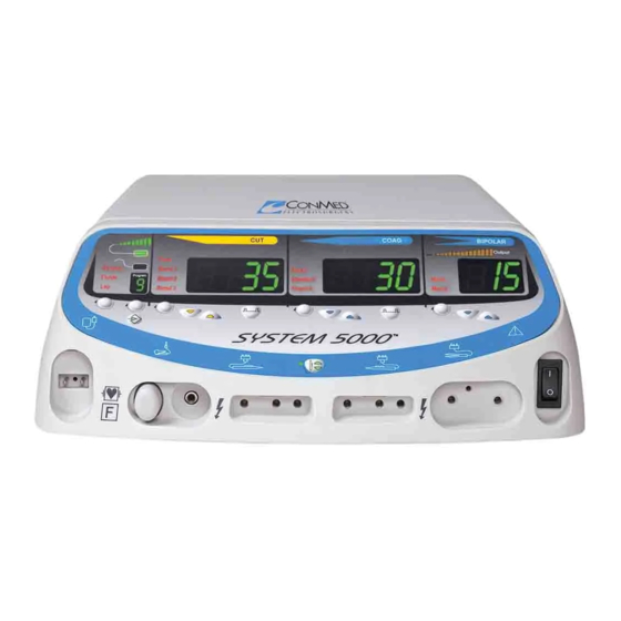
- Page 1 Service Manual E L E C T R O S U R G I C A L U N I T...
- Page 2 CONMED’s option) the same without charge, provided that routine maintenance as specified in this manual has been performed using replacement parts approved by CONMED. This warranty is void if the product is used in a manner or for purposes other than intended. STERILE EO ©...
-
Page 3: Table Of Contents
Table of Contents & List of Illustrations Section Title Page Theory of Operation ................... 3-1 Mode Descriptions ....................3-1 3.1.1 Cut Major Modes ..........................3-1 3.1.2 COAG Major Modes .........................3-1 3.1.3 Bipolar Major Modes ........................3-2 3.1.4 Advanced Specialty Modes ........................3-2 System Overview ..................... 3-2 3.2.1 High Voltage Power Supply (HVPS) ....................3-3 3.2.2... - Page 4 Section Title Page 4.7.4 Calibrating Bipolar Modes ......................4-16 4.7.5 Calibrating A.R.M.™ ........................4-16 4.7.6 Completing Calibration ........................4-17 Last Fault Code Retrieval and Clear ..............4-17 4.8.1 Last Fault Code Retrieval .......................4-17 4.8.2 Clearing Last Fault Codes .......................4-18 Displaying Optional System Configuration ............4-18 4.10 DACview ......................
-
Page 5: Theory Of Operation
Theory of Operation Section 3.0 System 5000™ functions and essential circuit information are provided in this section. This section begins with a description of the key parameters for each mode. This is followed by an overview of how the system functions and some key operational information for the modules within the system. -
Page 6: Bipolar Major Modes
provides further damping to dissipate the energy more quickly to minimize RF leakage effects. Spray Coag provides the maximum open circuit voltage for which the system is rated. 3.1.3 Bipolar Major Modes Major Minor RF fre- Modulation: Number of Modulation: Frequency & mode Mode quency... -
Page 7: High Voltage Power Supply (Hvps)
• The Monitor independently compares the Finally, the RF Controller minimizes RF leakage activation signal with that seen by the System currents using the CONMED Leakage Abatement Controller to ensure that the activation signal System (CLAS™), which imposes a duty cycle on is consistent. -
Page 8: Rf Amplifier And Transformer
Indicators: Power, Mode, Activation Keyboard & bipolar Real Time Modes / Power Displays Request current Clock (5K) Activation Relay ACT RLY Connector Serial Interface RS232 Connector AL TONE ACT TONE BIP TONE RF Output Patient Board System Controller VARM RLY DRV RF INH Transformer Board... -
Page 9: Electrosurgical Outputs
Monitor can independently disable transformer primary and secondary windings. Two Metal-Oxide-Semiconductor Field Effect The System 5000™ output panel connectors are Transistors (MOSFETs) are connected in a paral- illuminated to aid visibility in low lighting situ- lel fashion provide the switching. The pulses to ations. -
Page 10: Low Voltage Power Monitoring
RF Controller controls the fan based upon temperature measurements supplied from the Bipolar Current Meter: The System 5000™ RF Amplifier through the System Controller. has a bargraph display that provides an indica- tion of measured bipolar impedance. -
Page 11: 3.2.11 Activation Relay Connector
are individually adjustable, but alarm tones are not adjustable and are set to generate tone greater than 65 dB. Circuitry on the Backpanel PCB permits the Monitor to verify the oscillation from voltage measured across the speaker, which provides confirmation that the speaker is indeed generat- ing audible tones during activation. - Page 12 This page has been intentionally left blank.
-
Page 13: Maintenance
Ease of maintenance was a primary consideration in the design of the System 5000™. Maintenance features of this unit include microprocessor aided troubleshooting aids and push button calibration, Cover... -
Page 14: Bezel Removal And Replacement
Top Replacement: 3) Unlatch display ribbon cable, dispersive elec- trode connector, ReadiPlug™ cable connector 1) Place top approximately ¾” from front bezel and two ground connectors. on top of unit. 4) In most situations, it is not necessary to 2) Press forward, aligning lip of front bezel with remove the four power switch connectors. -
Page 15: Processor Board Removal And Replacement
4.3.3 Processor Board Removal and Replacement Processor Board Removal: 1) Remove Top. 2) Loosen the two screws holding the board to slots in the brackets. 3) Unlatch the ribbon cable going to the display. 4) Pull board up and out of unit. 3) Unlatch the ribbon cable and power cable on the top of the board. -
Page 16: Output Board Removal And Replacement
4.3.5 Output Board Removal and 4.3.6 RF Amp Board Removal and Replacement Replacement Output Board Removal: RF Amp Board Removal: 1) Remove Top, Bezel and Processor Board. 1) Remove Top, Bezel and Transformer Board. Note: It is not necessary to remove power switch 2) Remove the four screws that attach the connections from the bezel. -
Page 17: Low Voltage Power Supply Module Removal And Replacement
NOTE: This module is not user serviceable at the component level. If faulty, the entire cir- cuit board must be replaced. Replacements are available from CONMED Customer Service. Do not discard the module cover, mount- ing plate and hardware; the replacement part includes only the circuit board. -
Page 18: High Voltage Power Supply Removal And Replacement
4.3.8 High Voltage Power Supply Removal Note: Observe the position of the insulating sheet and Replacement under the High Voltage Power Supply. If the insulating sheet is removed, replace it as shown. High Voltage Power Supply Board Removal: It is important to maintain its function as a 1) Remove Top Cover. -
Page 19: Back Panel Board Removal And Replacement
Rear Panel with Back Panel Board Replacement: 1) Slide Rear Panel with Back Panel Board back into place on the unit. 2) Reinstall and tighten the seven screws and latch the ribbon cable. 4.3.10 Back Panel Board Removal and Replacement Back Panel Board Removal: 1) Remove Top Cover and Rear Panel. -
Page 20: 4.3.12 Power Transistor Replacement
Johnson Company. Formula 409® is a registered trademark of the Clorox Company. Periodic Inspection The System 5000™ should be visually inspected at least every six months. This inspection should include checks for the following: 1) Damage to the power cord and plug. -
Page 21: Periodic Performance Testing
Periodic Performance Testing 4.6.3 Output Power The System 5000™ should be tested for correct 1) Equipment Requirements: performance at least once every year. Every unit a) Monopolar Footswitch is supplied with a serialized Production Test Data b) Bipolar Footswitch Sheet that tabulates the results of the factory tests c) Commercial ESU Tester (e.g. -
Page 22: Rf Leakage Measurement
Table 4.2 Monopolar Coag Mode RF Output Power Accuracy Mode Load (ohms) Power Setting Watts (min) Watts (max) Amps (min) Amps (max) Spray 13.0 0.118 0.161 23.0 0.184 0.214 0.300 0.332 0.379 0.420 Standard 13.0 0.118 0.161 23.0 0.184 0.214 0.300 0.332 0.424... - Page 23 • Wooden table approximately 1 m from floor. command. Confirm no meter readings exceed NOTE: The CONMED Leakage Abatement the specified maximum. Hand control coag System (CLAS™) controls RF leakage by puls- activations are accomplished by connecting a...
-
Page 24: Line Frequency Leakage
Table 4.5 Allowable RF Leakage Current - Inactive Monopolar Outputs MEASURED TERMINAL ACTIVATED ACCESSORY MODE RF LEAKAGE (Ma) Footswitched Active Left Hand Controlled Standard Coag <50 Footswitched Active Right Hand Controlled Standard Coag <50 Footswitched Active Bipolar Footswitch Bipolar Macro <20 Left Hand Controlled Active Right Hand Controlled... - Page 25 5) Since the System 5000™ monopolar active see Table 4.8; while that output is activated outputs are disconnected by relays when the in Cut by the appropriate footswitch or hand unit is not activated, active-to-neutral leakage control jumper. Hand control cut activations...
-
Page 26: Output Coupling Capacitor Check
• “[V”, “[0A”, “bP”, or “Pad” will appear in The System 5000™ stores its calibration in non- the Monopolar Cut Power Digital Display to volatile semiconductor memory, so the calibration... -
Page 27: Figure 4.1 Calibration Procedure Flow Chart
Calibration Set the Calibration System Configuration Dipswitch on the Controller to the ON position Turn main power switch on. 888 888 88 Press Remote Power Control Key, release when tones begin. CAL rn Cu 500 P Press Remote Power Control Key. Press Monopolar Cut Power Adjustment Keys to select Cu, COA, bP and PAd. -
Page 28: Selecting The Mode To Calibrate
For all except the last of these, a single Press the activation. Press and release the Remote and release of the Remote Power Control Key is Power Control Key to complete the calibration required to proceed past this point on the menu. sequence for the selected minor mode. -
Page 29: Completing Calibration
Press and release the Remote Power Control Key tem in the Last Fault Code Mode (LFC). to begin calibration. The resistance to be used Electrosurgical outputs cannot be activated for calibration will appear in the Monopolar Coag while the system is in LFC. Power Digital Display. -
Page 30: Clearing Last Fault Codes
6) If the date defaults to 01 01 01 or the time entire fault code memory. The cut window defaults to 12P 0 1, then the Real Time Clock will display “[Lr” when codes are cleared. battery is low or the clock was not set on the •... - Page 31 Table 4.9 DIP Switch Settings Config. Title / Default Description for Off Description for On Switch Display Position Element TEST / Run Mode. Required position for Activates Test Mode, which inhibits most Cut 100’s surgery. of the system level monitoring for trouble- shooting purposes.
-
Page 32: Dacview
4.10 DACview 5) The Monopolar Cut Power Digital Display is used to display the selected DACview chan- DACview is a troubleshooting aid that allows nel. Since power was just initialized, the access to internal readings. The feature allows Monopolar Cut Power Digital Display will output voltage, current and power that the system display “0”... -
Page 33: Setting The Clock
4.11 Setting the Clock Press the STORE” key that is below the Program Window scroll key to lock the date The clock is only visible while in the Last Fault in memory. Display and the purpose of the clock is only to 6) Press PC key: the “Time”... - Page 34 Problem Possible Cause Display: [al The system is in the Calibration Mode. Calibration Mode is selected when the configuration DIP switch in the second position on the Controller assembly is in the ON (Up) position and the Remote Power Control Key is pressed and held while power is turned on.
-
Page 35: 4.12.1 Hvps Troubleshooting Hints
Problem Possible Cause Incorrect monopolar output Bad calibration – Recalibrate Ensure the load resistor is correct when checking output power. Bad voltage or current feedback. Check: • A7 RF_MP_VSN, monopolar voltage sense • A7 RF_MP_ISN, monopolar current sense • These signals should match the Monitor voltage and current sense, MRF_MP_VSN and MRF_MP_ISN, respectively. -
Page 36: Parts Ordering Information
CONMED distributor. To ensure prompt service, please provide the following information: Model Number Serial Number... - Page 37 Table 4.12 Fault Codes Description Possible Cause Things to check Correction Code Test or CAL mode The Remote Power Control Cycle system power while press- Replace the dip switch with no Key must be depressed ing the Remote Power Control Controller assembly.
- Page 38 Description Possible Cause Things to Check Correction Code RF controller boot- The program transmitted Cycle system power and deter- Replace the load program does from the System Controller mine if this error is repeated. Controller assembly. not match control- to the RF Controller ler ROM table through the HPI port at startup is faulty.
- Page 39 Description Possible Cause Things to Check Correction Code Pre-activation Prior to enabling Increase the tone volume by Replace the handshake, moni- electrosurgical output adjusting the Volume Control on Controller assembly. tor does not read a power, the Monitor ensures the back panel of the generator. Replace the Back tone signal that an activation tone is...
- Page 40 Description Possible Cause Things to Check Correction Code A.R.M.™ circuit The A.R.M.™ circuit on Verify proper voltage on the Replace the Output dropped below .4V the Output assembly or the VARM signal entering the assembly if VARM (circuit failed) A.R.M.™ sensing circuit on Controller assembly.
- Page 41 Controller assembly SPI mine if this error is repeated. Controller assembly. waiting for ADC circuitry. DMAs to finish RF Controller emu- Programming function only Return to ConMed. lation restart. Inter-processor Controller Assembly - Host Replace the communications Port Controller assembly.
- Page 42 Description Possible Cause Things to Check Correction Code POST memory Errors found in micropro- Cycle system power and deter- Replace the failure. cessor memories during mine if this error is repeated. Controller assembly. power initialization. RF Controller Calibration failed for one or Confirm proper load resistor and Repair or Replace rejected a calibra-...
- Page 43 Description Possible Cause Things to Check Correction Code POST RF AC volt- Monitor senses Configure the system for Replace the con- age cut feedback electrosurgical voltage out- Calibration mode operation and troller assembly, too low (A/D put too low during POST initialize power.
- Page 44 Description Possible Cause Things to Check Correction Code POST RF AC volt- Monitor senses See above. See above. age coag feedback electrosurgical voltage out- too low (A/D chan- put too low during POST nel 1) test, indicating insufficient voltage from HVPS, insuf- ficient drive from the RF Controller, failed RF Amplifier, or a failed voltage...
- Page 45 Description Possible Cause Things to Check Correction Code Calibration RF AC Monitor senses See above. See above. voltage coag feed- electrosurgical voltage out- back too low put too low during POST test, indicating insufficient voltage from HVPS, insuf- ficient drive from the RF Controller, failed RF Amplifier, or a failed voltage sensing channel.
- Page 46 Description Possible Cause Things to Check Correction Code Monitor sensed Excessive power at the Recalibrate the system. Repair or Replace 4x over power electrosurgical output was Configure the system for test the HVPS. condition for short detected for a short period mode operation and cycle power.
- Page 47 Description Possible Cause Things to Check Correction Code Monitor will not POST has determined that Verify that all cables are properly Repair or replace the disable high voltage the Monitor cannot disable connected. HVPS. during POST the HVPS. Configure the system for test Replace the The ribbon cable providing mode operation and verify prop-...
- Page 48 Description Possible Cause Things to Check Correction Code No tone feedback The Monitor did not detect Listen for tones during POST. Replace the during POST tones during POST. This Verify that all internal cables are Controller assembly. typically occurs because of a properly connected.
- Page 49 Description Possible Cause Things to Check Correction Code POST HVDC to The HVPS output is too Cycle system power and deter- Verify that all cables 30V failed- supply low during POST. mine if this error is repeated. are properly con- too low Watch LED2 on the HVPS dur- nected.
- Page 50 Description Possible Cause Things to Check Correction Code POST monitor Reset machine and if Cycle system power and deter- Replace the timed out- did not error repeats, then replace mine if this error is repeated. Controller assembly. respond to a POST Controller Assembly command Dial setting over...
Need help?
Do you have a question about the SYSTEM 5000 and is the answer not in the manual?
Questions and answers