
Summary of Contents for Artistic Licence Micro-Scope 3c
- Page 1 Micro-Scope 3c User Guide Artistic Licence Engineering Ltd Firmware v1.7 User Guide v8.3...
-
Page 3: Table Of Contents
Introduction ............................7 DMX output / RDM Connection ......................7 DMX input ............................7 Power ..............................7 9V PSU ............................. 7 Battery ............................. 8 Menu Navigation..........................8 Top Menu ............................9 DMX512 Menu ............................ 9 DMX - TRANSMIT Menu ........................9 DMX - TRANSMIT - CHANNEL Menu ..................... - Page 4 Get the start address of the second root device ..............25 Get the footprint of the second device’s second sub-device ........... 26 Set the start address of the first root device ................26 Set the names of both devices ....................26 RDM Feedback ..........................
- Page 5 Compliance ............................42 Waste Electrical & Electronic Equipment (WEEE) ................42...
-
Page 7: Introduction
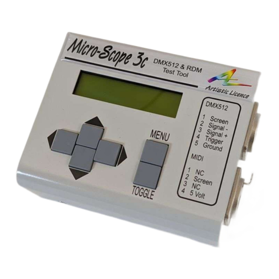
Introduction Micro-Scope 3c is a battery-powered, hand-held tool for transmitting and receiving DMX512, commissioning RDM devices and testing cables and DMX512 infrastructure. If you have purchase the Micro-Scope 3c upgrade kit, please view this video for installation details. DMX output / RDM Connection The DMX output / RDM connection is made via the female XLR5 on the right panel. -
Page 8: Battery
Battery Micro-Scope 3c is designed to run on battery power for extended periods using the internal NiCd battery pack. The power switch is used to switch off Micro-Scope 3c, battery charging will continue if the power connector is energised. Start-up Micro-Scope remembers the last used function on start-up. -
Page 9: Top Menu
Top Menu The top menu provides access to numerous operational and configuration menus. Keys operate as follows: LEFT Navigates to higher level menu if it is available. RIGHT Navigates to sub-menu if it is available. UP and DOWN Select entry from the current menu. Access the menu function if the K is displayed, otherwise it behaves as if RIGHT is TOGGLE pressed. -
Page 10: Dmx - Transmit - Channel Menu
SCENE Playback one of forty recorded scenes. SNAPSHOT Snapshot (record from received DMX) into any of the forty scenes. FIXTURE Transmit DMX to control intelligent fixtures based on a personality library. CONFIG Setup numerous timing parameters for transmitted DMX. DMX - TRANSMIT - CHANNEL Menu This menu allows transmission of a single channel (aka data slot) of DMX at any level. -
Page 11: Dmx - Transmit - Scene Menu
If you need to go to the stage or outside a building to check lamps, this menu allows an automatically changing test pattern to be transmitted. Hint: Check the Standby Timer to ensure Micro-Scope 3c does not power down when you are away! DMX – TRANSMIT - SCENE Menu The DMX-TRANSMIT-SCENE menu is used to playback and edit any of the forty scenes. -
Page 12: Dmx - Transmit - Snapshot Menu
When would I use this? If you have some useful test patterns setup on the lighting console, use this menu to transfer then to Micro-Scope 3c. DMX – TRANSMIT - CONFIG Menu The DMX-TRANSMIT-CONFIG menu is used to set numerous DMX transmit parameters. This menu should be used with caution as it intentionally allows the user to set parameters which result in illegal DMX transmission. - Page 13 Parameter Description Default Legal Legal Value number of bytes in addition to the Start Code that are contained in the DMX packet. Break The Break is the synchronization that 200us 40us 20ms 92us* indicates the start of DMX packet. The MaB or Mark after Break is the 20us 20ms 12us* idle period between the end of Break...
-
Page 14: Dmx - Receive Menu
DMX - RECEIVE Menu The DMX-RECEIVE menu provides eight options. Use UP and DOWN to navigate and then press TOGGLE. |<STATUS MENU | RECEIVE The sub-menus are: STATUS Set receive Start-Code and view receive status. GRAPH Display a bargraph of the levels of up to 30 consecutive channels. DECIMAL Display the decimal levels of up to 6 consecutive channels. -
Page 15: Dmx - Receive - Graph Menu
The top line provides an icon display that provides insight into the types of data being received: Zero start code DMX is being received. RDM (Remote Device Management) is being received. Zero start code DMX and RDM is being received. RDMX Non-Zero start code DMX is being received. -
Page 16: Dmx - Receive - Decimal Menu
Zero start code DMX and RDM is being received. Non-Zero start code DMX is being received. DMX with errors is being received. The display shows a low-resolution bargraph of the levels of 24 consecutive channels from the received DMX of the start code defined in DMX-RECEIVE-STATUS. When would I use this? If you need to see the big picture rather than exact detail on channels levels. -
Page 17: Dmx - Receive - 16-Bit Menu
LEFT and RIGHT Select the required start address for the received DMX display. The display will change to show the first and last channel displayed. UP and DOWN Select the required start address for the received DMX display. The display will change to show the first and last channel displayed. - Page 18 UP and DOWN Select the required start address for the received DMX display. The display will change to show the first and last channel displayed. TOGGLE Reset the minimum and maximum data (ellipsis will be displayed in each field). In the example below, the min and max fields have been reset and no flicker has been detected. The current received level is 255: Now: ...
-
Page 19: Dmx - Receive - Stats Menu
DMX – RECEIVE - STATS Menu The DMX-RECEIVE-STATS menu is used to display numerous DMX receive parameters. The parameters displayed relate only to received DMX with start code defined in DMX-RECEIVE-STATUS. Keys operate as follows: LEFT and RIGHT Not used. UP and DOWN Select the required parameter. -
Page 20: Dmx - Rdm Menu
DMX - RDM Menu The DMX-RDM menu provides six options. Use UP and DOWN to navigate and then press TOGGLE. RDM is an abbreviation for Remote Device Management. It is the bi-directional protocol that works through DMX to allow the reading and writing of parameters (called get and set) along with reading sensors and other device status. -
Page 21: Dmx - Rdm - Patch Menu
Done 6 When would I use this? You need to perform discovery once after powering on Micro-Scope 3c, and prior to using any other function in the DMX-RDM menu. You should also perform discovery if you add or remove any devices to the DMX cable. -
Page 22: Get The Start Address Of The First Root Device
The following examples show how these option fields are used. In the examples we are connected to two Artistic Licence sunDial dimmers. These are 4-channels devices that have 5 personalities and 4 sub-devices. The sub-devices can accept individual start addresses and personality. -
Page 23: Dmx - Rdm - Auto-Add Menu
“Smoke machine low on oil” to an emergency such as “Dimmer on fire”. Micro-Scope 3c uses the red / green backlight to highlight the urgency of these messages. Keys operate as follows: LEFT and RIGHT Navigate through the option fields. -
Page 24: Get The Status Messages From The First Root Device
If ALL devices and/or ALL sub-devices is selected, BROADCAST is displayed. The following example shows how this is used. We are connected to an Artistic Licence sunDial dimmer. Get the status messages from the first root device Use the LEFT, RIGHT, UP, DOWN keys to set the device to 001. -
Page 25: Get The Start Address Of The First Root Device
The following examples show how these option fields are used. In the examples we are connected to two Artistic Licence sunDial dimmers. These are 4-channels devices that have 5 personalities and 4 sub-devices. The sub-devices can accept individual start addresses and personality. -
Page 26: Get The Footprint Of The Second Device's Second Sub-Device
Use the LEFT, RIGHT, UP, DOWN keys to set the PARAMETER to START ADDR. Micro-Scope 3c gets the parameter and displays it in the 002-000 START AD DATA field. In this example a start address of 005. Get the footprint of the second device’s second sub-device... -
Page 27: Rdm Feedback
-- ACK --, which indicates that the RDM device has accepted the command. It the RDM command cannot be accepted by the device, Micro-Scope 3c displays the Negative Acknowledge as detailed below. Further details available in the RDM standard E1.20 Table A-17. - Page 28 LCD Display Comment Value Proxy buf full The RDM device reports that its proxy buffer is full and 0x000A can store no more messages. Not supported The RDM device does not support the requested 0x000B action. Endpoint invalid The RDM device reports that the specified endpoint is 0x000C invalid.
-
Page 29: Dmx - Rdm - Sensors Menu
‘Fan speed’. VALUE The value of the sensor. The following example shows how this is used. We are connected to an Artistic Licence sunDial dimmer. Get the first sensor from the first root device Use the LEFT, RIGHT, UP, DOWN keys to set the device to 001... - Page 30 When would I use this? When a particular device is suspected of a fault, this allows you to continuously monitor sensors.
-
Page 31: Dmx - Advanced Menu
DMX - ADVANCED Menu The DMX-ADVANCED menu provides four options. Use UP and DOWN to navigate and then press TOGGLE. All the options are based on receiving DMX while transmitting. |<LOOP MENU | FIX RX The sub-menus are: LOOP View received DMX while transmitting a range of channels. FIX-RX Receive DMX, correct errors and re-transmit. -
Page 32: Dmx - Advanced - Fix Rx Menu
This function uses the DMX test packet to check for data loss in a DMX network. The output of Micro-Scope 3c should be connected to the primary input to your DMX network (i.e instead of the lighting console or ethernet gateway output). The Micro-Scope 3c input should be connected to the output of the splitter you wish to test. - Page 33 The display shows a real-time analysis of the test. The transmit DMX timing is: Parameter Value Data Slots Break 96us 12us 16us When would I use this? If you suspect that something in the DMX infrastructure (Splitter, cable) is causing interference with the data, this allows you to transmit high speed data packets and confirm they are received correctly.
-
Page 34: Dmx - Advanced - Bobulate Menu
Parameter Description Break Start Slots Data Data Code Slots Slot Value All ch off Micro-Scope 3c 200uS 20us 16us transmits good DMX with a 512 data slot payload and all levels at zero. All DMX receivers should accept this. Legal packet. - Page 35 20us continuously sends a break and start code with no slots. Some DMX responders can be upset by this. Legal packet. Long pack Micro-Scope 3c sends 200us 20us 1001 1000 16us packets with 1000 data slots. This is primarily useful for development testing.
- Page 36 Parameter Description Break Start Slots Data Data Code Slots Slot Value Short MaB Micro-Scope 3c sends 200us 16us packets with a short MaB. This is primarily useful for development testing. Illegal packet -4us One St-bit Micro-Scope 3c sends 200us 20us...
-
Page 37: Dmx - Cable Menu
DMX - CABLE Menu The DMX-CABLE menu provides four options. Use UP and DOWN to navigate and then press TOGGLE. All the options allow cables to be tested. CABLE|<DOUBLE MENU | SINGLE The sub-menus are: DOUBLE Double ended cable test for connectivity on ground, data- and data+. SINGLE Single ended cable test. -
Page 38: Good Cable
LEFT and RIGHT Not used. UP and DOWN Not used. TOGGLE Not used. To use the tester, connect the cable to the transmit port. Note that this is a continuity test and so cannot be used with any electronics – it only tests cable. The display shows connectivity between data- and data+. -
Page 39: Utils Menu
50. ST’BY TIME The time in minutes, that Micro-Scope 3c will wait after any key press before entering power saving mode. The standby timer is inhibited when USB power is connected. Set a value of zero to disable the standby timer. Maximum value is 240 minutes. -
Page 40: Utils - Backlight Menu
UTILS - BACKLIGHT Menu This menu is used to configure backlight brightness for different functions. Settings are stored in flash memory and so will be retained between power cycles and when batteries are removed. Keys operate as follows: LEFT and RIGHT Navigate through the option fields. -
Page 41: Glossary
Glossary Channel There are a maximum of 512 channels in a DMX packet. This term is identical to Data slot. Channels number from 1 – 512. Slot Slot refers to the 513 bytes that can be contained in a DMX frame. Slots number from 0 – 512, zero being the start code. -
Page 42: Warranty
UKCA, CE and RoHS regulations. Product specific information is available on request. Waste Electrical & Electronic Equipment (WEEE) Artistic Licence is a member of a WEEE compliance scheme and will happily recycle any of our products that you, at your expense, return to us. - Page 43 Artistic Licence Engineering Ltd. shall not be liable for errors contained herein or for incidental or consequential damages in connection with the furnishing, performance or use of this material.
Need help?
Do you have a question about the Micro-Scope 3c and is the answer not in the manual?
Questions and answers