
Subscribe to Our Youtube Channel
Related Manuals for BTL 6000 SWT TOPLINE


Summary of Contents for BTL 6000 SWT TOPLINE
- Page 1 BTL-6000 SWT TOPLINE USER’S MANUAL v100AS08/01/2010EN GENERAL CHARACTERISTICS OF THE DEVICE | PAGE 1 OF 38...
- Page 2 BEFORE YOU START Dear Customer, Thank you for purchasing BTL technology. All of us at BTL wish you every success with your system. We pride ourselves on being as responsive as possible to our customers’ needs. Your suggestions and comments are always welcome since we believe an ongoing relationship with our customers is critically important to our future product line.
-
Page 3: Table Of Contents
Possible side Effects of Shockwave Treatment........................7 Indications for Shockwave Treatment ..........................8 Contra-indications for Shockwave Treatment........................8 INSTRUCTIONS FOR OPERATION............................9 The Front Panel of the BTL-6000 SWT Topline ........................9 Applicator for BTL-6000 SWT Topline ..........................9 The Rear Panel of the BTL-6000 SWT Topline.........................10 Assembly and Set-Up...............................11 Basic Displays and Operating of the Device ........................12... - Page 4 2.11.3.8 Operation Mode ..............................23 2.11.3.9 Touch Panel Calibration............................23 2.11.3.10 User Options................................23 2.11.3.11 Setting of HW Key ..............................23 2.11.3.12 Unit Information ..............................23 2.11.3.13 Unlock Code ................................23 2.11.3.14 Service Functions ..............................24 2.11.4 Specific Settings ................................24 2.11.4.1 Applicator Button Mode............................24 2.11.4.2 Applicator Kit Replacement Wizard .........................24 LIST OF STANDARD AND OPTIONAL ACCESSORIES ....................25 MAINTENANCE AND SAFETY INSTRUCTIONS........................26 4.1.1...
-
Page 5: General Characteristics Of The Device
A time-saving feature of the BTL-6000 SWT Topline is the predefined programs stored in the memory of the main unit. Based on detailed research and practical use of the device, the well-organized predefined programs will provide recommendations for the treatment of various conditions. -
Page 6: Shockwave And Its Character
Several types of generators have been developed for shockwave therapy, each producing shockwaves with varied characteristics. Each type of generation method induces shockwaves with different time progressions and spatial arrangements. The BTL-6000 SWT Topline uses the ballistic principle of shockwave generation. 1.3.1 BALLISTIC PRINCIPLE OF SHOCKWAVE GENERATION A pressure wave is formed via a projectile by using accelerated compressed air. -
Page 7: Biological Effects Of Shockwave Treatment
1.4 BIOLOGICAL EFFECTS OF SHOCKWAVE TREATMENT The effects of the shockwaves mainly occur at sites where there is a change in impedance, such as the bone-soft tissue interface. There is an improvement in the regeneration and repair of tissues in the following areas and the achievement of the following effects: •... -
Page 8: Indications For Shockwave Treatment
1.7 INDICATIONS FOR SHOCKWAVE TREATMENT • Plantar Fasciitis • Achillodynia/Achillobursitis • Inflammations and calcification of shoulder joint tendons. • Pain in the groin area. • Epicondylitis (Tennis and Golf Elbow) • Apex Patellae Syndrome and Tibial Stress Syndrome. • Pain in the hip area and/or the iliotibial tract. •... -
Page 9: Instructions For Operation
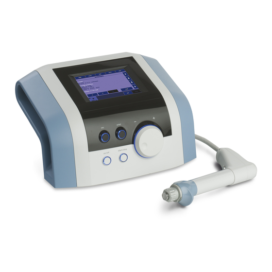
2 INSTRUCTIONS FOR OPERATION THE FRONT PANEL OF THE BTL-6000 SWT TOPLINE 10 3 10 4 10 5 10 2 touch screen select knob (to select individual parameters) enter key esc key start / stop key (to start and stop therapy) ON/OFF switch (back lit, in blue, when the control unit is ‘’on’’... -
Page 10: The Rear Panel Of The Btl-6000 Swt Topline
THE REAR PANEL OF THE BTL-6000 SWT TOPLINE connector for shockwave applicator control unit mains fuse connector for power cable power on/off switch vessel for collecting condensed water type label – contains type of the device, manufacturer and safety and warning signs... -
Page 11: Assembly And Set-Up
Do not place the device close to appliances producing strong electromagnetic, electric or magnetic field (diathermy, X-rays, etc.), otherwise it could be undesirably influenced. In the event of any questions, please contact an authorized service of BTL devices. Procedure: First connect the device in mains by means of the supplied power supply adapter, which you will connect to the connector on the rear panel of the device and to a 100 V or 240 V mains socket. -
Page 12: Basic Displays And Operating Of The Device
BASIC DISPLAYS AND OPERATING OF THE DEVICE 2.5.1 INITIAL SCREEN AND TYPES OF TABS The initial screen after the switch-on of the device contains the tab displaying information about the connected accessories. Examples of information shown on the tabs: Indicates that no accessories are connected Indicates that the applicator is connected and shockwave therapy can be applied. -
Page 13: Numeric Keypad
2.5.3 NUMERIC KEYPAD In addition to setting the numerical values with the select knob on all the screens, the ”numeric keypad" can be use for the faster setting of values. This is the icon for the opening of the numeric keyboard window: Press the numeric keypad button to display the window with the numeric keypad for the parameter with the “pressed”... -
Page 14: Setting Therapy Parameters Manually (User Setup) Via The 'Man' Button
2.6.3 SETTING THERAPY PARAMETERS MANUALLY (USER SETUP) VIA THE ‘MAN' BUTTON The therapy parameters screen for the user (manual) setting will be displayed by pressing the man button. All specifications of the therapy can be set and possibly saved as a user program or a diagnosis. Pressing of individual buttons will open an individual menu and pop-up boxes for the settings. -
Page 15: Setting Therapy Intensity
The endless therapy option allows for an infinite number of shocks, that can be applied from the start of the therapy. The end of therapy is not limited to the number of shocks. 2.6.5 SETTING THERAPY INTENSITY The intensity (power) of the shockwave therapy can be set on the therapy parameters screen, even during the course of therapy. -
Page 16: Therapy Parameters Screen - Ergonomic, Standard And Expert Mode
2.6.6 THERAPY PARAMETERS SCREEN – ERGONOMIC, STANDARD AND EXPERT MODE This screen always appears before the start of therapy when the diag or prog buttons are pressed (see Diagram of the therapy setting process). If only the most important therapy parameters are shown, then the ergonomic operation mode was selected. -
Page 17: Running Therapy Screen
2.7.2 RUNNING THERAPY SCREEN Name of selected therapy / program and the set parameters Set frequency Number of applied shocks Set number of shocks Set intensity Number of remaining shocks Icon and name of connected accessories Time of applied therapy Symbolic description of generated output 2.7.3... - Page 18 Examples of how to hold the shockwave applicator These examples illustrate the application of shockwaves in different areas and several of ways of holding the applicator. Painful shoulder Trigger-points Tibial Edge Syndrome Calcar Calcanei (Plantar Fasciitis) Epicondylitis Achillodynia Patellar Tendinopathy (Jumper’s Knee) Trigger points INSTRUCTIONS FOR OPERATION | PAGE 18 OF 38...
-
Page 19: Saving Therapy
SAVING THERAPY A particular operation can selected after pressing the “save” button. Depending on which operation is selected, a chart with the appropriate data will be shown. An example of the procedure is displayed on the following screens. It is always possible to save the therapy after setting its parameters, for example from the screen of therapy parameters – see the chapter Therapy parameters screen. -
Page 20: Clients
2.10.1 CLIENTS This feature allows the entering, editing and deleting of information about clients. A particular therapy can be assigned to each client. 2.10.2 USER DIAGNOSES/PROGRAMS This feature makes it possible to start the user therapies, to adjust their parameters, names and descriptions, to delete them and to sort them by using the buttons and choices shown on the screen. -
Page 21: Information
The memory-chip contains a lot of information and reading it takes from 30 seconds to 2 minutes. The “installation of accessories” function serves for faster functioning of the unit. After the installation, under normal operation of the device only the serial number of the accessory is read from the accessory’s memory and the other information is read from the device’s memory. -
Page 22: Unit Settings
2.11.3 UNIT SETTINGS This submenu offers the options of setting and displaying these parameters: • Password setting • Sound setting • Screen saver and auto switch-off • Colour setting • Setting of display contrast • Date and time setting • Language setting •... -
Page 23: Setting Of Display Contrast
2.11.3.5 Setting of Display Contrast Allows the setting of the optimum contrast (readability) of the display by turning the select knob. Since the contrast of the screen depends on various factors, such as the temperature of the room, there is a faster and direct way of setting the screen contrast. -
Page 24: Service Functions
2.11.3.14 Service Functions • repair of files Checks the file storage system of the device, the system of saved information. It will repair possible errors, delete empty files, etc. We recommend using this feature in the event of a lack of memory space, if the device rejects saving any data, or if you are in doubt that some data may have been lost. -
Page 25: List Of Standard And Optional Accessories
1x spare fuse T6.3A,L,250V • 1x User’s Manual on CD Optional accessories: • transport case for the BTL-6000 SWT Topline • additional shockwave applicator with focusing shock transmitter • gel 300 ml LIST OF STANDARD AND OPTIONAL ACCESSORIES | PAGE 25 OF 38... -
Page 26: Maintenance And Safety Instructions
Exterior cleaning of the device: Use a soft cloth slightly moistened with water or with a 2% detergent solution to clean the exterior of the BTL-6000 SWT Topline device and its parts. Never use cleaning agents containing alcohol, ammonia, benzine, thinners, etc. Never use abrasive cleaning materials which will scratch the device's surfaces. -
Page 27: Shock Transmitter Replacement Procedure
4.1.1 SHOCK TRANSMITTER REPLACEMENT PROCEDURE The shock transmitter can be replaced as necessary. Three shock transmitters are included as part of the BTL-6000 SWT Topline standard accessories: • 1x replaceable multi-focus shock transmitter (Ø 15mm) • 1x replaceable multi-focus shock transmitter (Ø 9mm) •... -
Page 28: Procedure Of Worn-Out Tube And Projectile Replacement
If the applicator stops working correctly after some amount of time, then it is possible to change the worn-out parts of the tube and projectile by using the spare parts kit included in the BTL-6000 SWT Topline package. Do not use damaged applicators! There is a risk of injury to the operating staff or the client. - Page 29 Use the key to unscrew the screw cap of the cartridge. See the pictures below. Remove the worn-out part from the cartridge from the applicator Remove the plastic cover from a new replacement part. MAINTENANCE AND SAFETY INSTRUCTIONS | PAGE 29 OF 38...
- Page 30 Insert the shock transmitter back into the applicator, including both of its O-rings. 10. Put the shock transmitter screw cap back in place and screw it on tightly by hand. 11. Reconnect the applicator to the BTL-6000 SWT Topline device. MAINTENANCE AND SAFETY INSTRUCTIONS | PAGE 30 OF 38...
-
Page 31: General Safety Precautions
If the source of the concern can be determine after a thorough study of the user's manual, then contact an authorized BTL service department immediately. If the device is not used in accordance with this manual or if it is used when the device exhibits functional differences from those stated in this manual, then BTL is not responsible for any damage to or caused by the device. -
Page 32: Used Symbols
BTL's sole obligations under this warranty are as set forth herein. In no event shall BTL be liable for any lost revenue or profits, direct, indirect, special, incidental or consequential damages of any kind. -
Page 33: Technical Parameters
5 TECHNICAL PARAMETERS Identification of the device B T L - 6 0 0 0 S W T T o p l i n e Operating conditions Ambient temperature + 10 ° C to + 40 ° C Relative humidity 30 % to 75 % Atmospheric pressure 700 hPa to 1060 hPa... - Page 34 Technical parameters of the Switching Power Supply Adapter BTL-4000 SWT 150W Design Weight – device only 780 g approx. Dimensions (w x h x d) 142 x 76 x 43,7 mm Covering grade according to EN 60 529 IP20 Class according to IEC 60601-1...
-
Page 35: Emc Information
Directive and declaration of manufacturer – Electromagnetic Emission BTL-6000 SWT Topline is suitable for use in the specified electromagnetic environment. The purchaser or user of BTL-6000 SWT Topline should assure that it is used in an electromagnetic environment as described below... - Page 36 Directive and declaration of manufacturer – Electromagnetic immunity BTL-6000 SWT Topline is suitable for use in the specified electromagnetic environment. The purchaser or user of BTL-6000 SWT Topline should assure that it is used in an electromagnetic environment as described below.
-
Page 37: Applicable Standards
5.2 APPLICABLE STANDARDS Name IEC, MDD EN, ISO, Medical electrical equipment – IEC 60601-1:2005 EN ISO 60601-1:2007 Part 1: General requirements for basic safety and essential performance Medical electrical equipment Part 1: General requirements for safety 1.Collateral standard: Safety IEC 60601-1-1:2000 EN ISO 60601-1-1:2001 requirements for medical electrical systems Medical electrical equipment –... -
Page 38: Manufacturer
Except as required by applicable law, no warranties of any kind, either expressed or implied, are made for the accuracy, reliability or contents of this document. BTL Industries Limited reserves the right to revise or withdraw this document at any time without prior notice.
Need help?
Do you have a question about the 6000 SWT TOPLINE and is the answer not in the manual?
Questions and answers