Table of Contents
Advertisement
Quick Links
MV52 Installation Guide
Overview
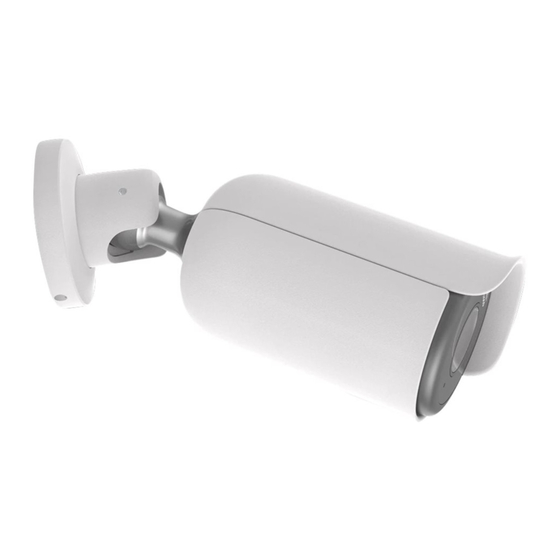
The Cisco Meraki MV52 is the first varifocal bullet camera in the second-generation smart camera family. Aligning with
our other cameras, it eliminates the complex and costly servers and video recorders required by traditional solutions
which removes the limitations typically placed on video surveillance deployments.
Datasheet here:
Click here
FAQ and Troubleshooting MV52:
Click here
Dimensions
Box Contents
A single camera box contains:
• One camera hardware
1
Advertisement
Table of Contents

Related Manuals for Cisco MERAKI MV52

Summary of Contents for Cisco MERAKI MV52
- Page 1 MV52 Installation Guide Overview The Cisco Meraki MV52 is the first varifocal bullet camera in the second-generation smart camera family. Aligning with our other cameras, it eliminates the complex and costly servers and video recorders required by traditional solutions which removes the limitations typically placed on video surveillance deployments.
-
Page 2: Pre-Install Preparation
Powering the MV52 The MV52 features a 1000BASE-TX Ethernet port with 802.3at PoE+ and requires 30W of power to run. Route the Ethernet cable from an active port on a PoE switch or PoE injector. Additionally, a 12V DC input option is available as well. -
Page 3: Install Instructions
*.devices.meraki.direct and that these domain requests are forwarded to Google public DNS. Assigning IP Addresses At this time, the MV52 does not support static IP assignment. MV52 units must be added to a subnet that uses DHCP and has available DHCP addresses to operate correctly. Install Instructions Each MV52 comes with an instruction pamphlet within the box. -
Page 4: Placement Guidelines
Placement Guidelines There are three ways in which you can mount the MV52. They are as follows: Wall or ceiling Pole (with accessory) Pole mount MA-MNT-MV-21, custom made for MV52 is available to order separately. -
Page 5: Mounting Instructions
The MA-MNT-MV-21 can be mounted on a pole (>40 mm currently supported) as below: • Attach the pole mount to hug the pole • Drag a metal cable tie around the top/bottom of this mount Considering the weight of this camera, it is recommended to use safety cable wires Adjacent to a junction box (no conduit adapter-in-box) Adjacent mounts to a 3.5'' junction box would be ideal Mounting Instructions... - Page 6 1. Place the mounting template onto the surface (wall/ceiling) and drill six holes as well as the center hole, as marked (if needed). 2. The following inputs are currently available for the MV52: • A - PoE+ input • B - 2 pin 12VDC input...
- Page 7 3. Pass the cable through the center hole and plug it in. Then, in an anti-clockwise direction, unscrew the top of the base from the rest of the camera. 4. At this point, you will need something to support the base of the camera, or let it hang off of its cable and the base. Drill in the six provided screws (or any appropriate screw with less than 8.6 mm head size) onto the base and into the surface.
- Page 8 6. In a clockwise motion, rotate the top of the base to affix the camera to the base, while leaving some space to rotate and aim the camera later. 7. With the base top aligned to the base, rotate the camera using the ball joint to fix your field of view/angle. Ensure that the opening is facing the direction in which the camera needs to look, and that the hood is on the top.
-
Page 9: Led Indicator
9. Tighten this even further by using the M5 and M2.5 torx keys provided around the joint and the top of the base. 10. Remove the green IR safely label once you have finished positioning your MV52. LED Indicator The various status conditions of an MV are indicated by the following colors and patterns: •... - Page 10 • Solid Blue - MV is connected via WiFi. • Solid Violet - MV has audio recording enabled. • Solid Amber - MV has a network issue and cannot talk to dashboard • Solid Red - Power connection is below <7.8V...
Need help?
Do you have a question about the MV52 and is the answer not in the manual?
Questions and answers