
Related Manuals for Thermo Scientific RVT5105


Summary of Contents for Thermo Scientific RVT5105
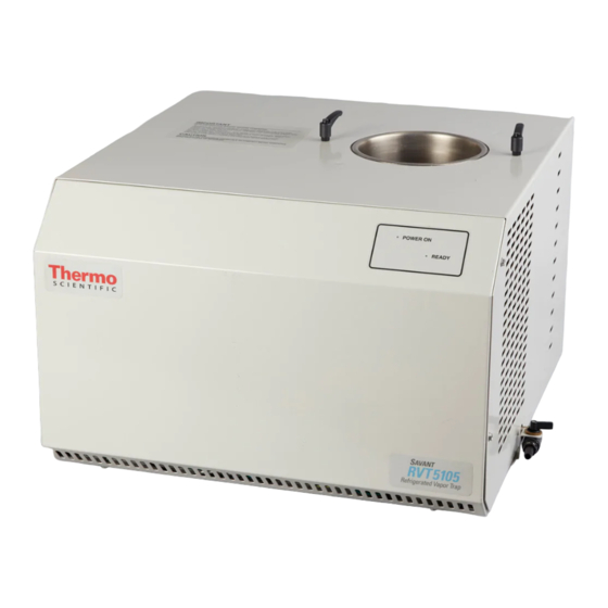
- Page 1 Thermo Scientific RVT5105 Refrigerated Vapor Traps Installation and Operation 128-3000-51 March 2012...
- Page 2 IMPORTANT Failure to follow the instructions in this manual can result in damage to the unit, injury to operating personnel, and poor equipment performance. CAUTION All internal adjustments and maintenance must be performed by qualified service personnel. Material in this manual is for informational purposes only. The contents and the product it describes are subject to change without notice.
-
Page 3: Table Of Contents
Table of Contents Table of Contents Description................1 Receiving and Inspection ............2 Receiving .................2 Unpacking ................2 Inspection................2 Installation ................2 Site preparation................2 Other Components ..............3 Preparing for Operation ............3 GCF400...................4 GF4000 (use with SC250EXP only) ........5 Tubing Connections ..............7 Operation .................8 Sequence of Operation.............8 Emptying the Glass Vessel............8 Maintenance and Troubleshooting .........10... -
Page 4: Description
Operating temperature is -105 The RVT5105 is controlled simply by an on/off (I/O) switch located on the left side. An amber LED on the right front indicates that the unit is on. A green LED indicates that the operating temperature has been reached and the unit is ready to use. -
Page 5: Receiving And Inspection
Provide adequate ventilation. Thermo refrigerated traps are air-cooled and require at least 3 inches (7.62cm) of clearance for ambient air suction. The RVT5105 draws air from the rear of the unit. Ambient temperature must not exceed +90 °F (+32 °C) during operation. -
Page 6: Other Components
Before each use, be sure the chamber is filled to the correct level. If necessary. add more CryoCool. Cryocool can now be drained from the RVT5105 system to remove unwanted ice or other contaminates after the system has been fully defrosted. -
Page 7: Gcf400
The figure below shows the GCF400 installation in the RVT5105 chamber. To the left is an insulation “lift and turn”retaining clip. -
Page 8: Gf4000 (Use With Sc250Exp Only)
Installation The figure below shows the GCF400 with the black insulation ring, locked down in the chamber by means of the retaining clips. Figure 2. GCF400 locked down in chamber This will fully seal the chamber. Withdraw the flask again and verify that the level of CryoCool came to within about a half-inch (12–15 mm) from the top (shoulder) of the flask. - Page 9 Installation The following figures illustrate GF4000 condensation flask installation. Figure 3. GF4000with insulation ring Figure 4. GF4000 locked down with retaining clips Figure 5. GF4000 with SC250 vacuum cap installed Thermo Fisher Scientific...
-
Page 10: Tubing Connections
Installation To install the GF4000, place a clean, dry Glass Condensation Flask into the stainless steel chamber. Fit the black insulating cover over the flask. Lift and rotate the two black retaining clips to hold down both the insulation ring and the glass flask. -
Page 11: Operation
After preparing the unit as described in Section 3 on page 2, switch it ON. Operation The power switch is located on the left side of the RVT5105. An amber LED on the front illuminates when power is on. It may take up to 90 minutes for the trap fluid to reach its operating temperature. - Page 12 Operation To remove the GCF400 or GC4000 for cleaning: 1. Bleed the system back to atmospheric pressure. 2. Remove the rubber flask cover from the flask on the GCF400 or by unscrewing the poly nut on the vacuum connector used on the GC4000, leaving tubing attached to cover.
-
Page 13: Maintenance And Troubleshooting
The RVT5105 has a drain valve that allows you to removed the defrosted Cryocool and water contaminates directly from the condenser. To operate the valve: Turn the unit off and allow it to defrost (this could take several hours);... -
Page 14: Vibration
Maintenance and Troubleshooting valve closed Figure 7. Drain valve closed To reuse CryoCool that has a layer of water, transfer it to a container and allow to settle again into a bilayer. Place in a freezer until the water layer freezes. -
Page 15: Specifications
Specifications 6 Specifications Operating temperature: -105 Capacity: 4 liters Dimensions (W x D x H) Inches: 24.1 x 23.9 x 17.6 Cm: 61.2 x 60.7 x 44.7 Net shipping weight: 170 lbs. (77 kg) Power requirements: 115 VAC/60 Hz, 13A 230 VAC/50 Hz, 7A 230 volt models are designed to conform with CE standards. -
Page 16: Accessories
Accessories 7 Accessories GCF400 Glass Condensation Flask (wide-mouth) GF4000 Glass Wide Mouth Flask (threaded) (Used with SC250EXPonly) FC400 Flask Cover (black rubber) for GCF400 145-6012-00 Insulating Cover (white foam) for GCF400 SCT120 Chemical Trap DC120A Disposable Cartridge for SCT120 when trapping acid and water vapors. -
Page 17: Warranty
Warranty 9 Warranty All Thermo Fisher Scientific products mentioned in this manual) excluding glassware) are warranted against defects in workmanship for one year after the date of delivery to the original purchaser. This warranty is limited to defective materials and workmanship and does not cover incidental or consequential damages. - Page 18 Thermo Fisher Scientific Inc. 275 Aiken Road Asheville, NC 28804 United States www.thermofisher.com 128-3000-51...
Need help?
Do you have a question about the RVT5105 and is the answer not in the manual?
Questions and answers