Table of Contents
Advertisement
Quick Links
Service Training Manual
Specifications
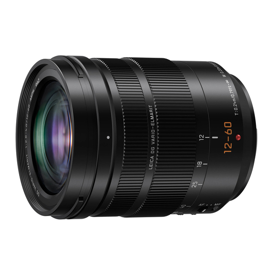
INTERCHANGEABLE LENS FOR DIGITAL CAMERA
"LUMIX DG VARIO-ELMARIT 12-60 mm/F2.8-4.0 ASPH./POWER O.I.S."
Focal length
Aperture type
Maximum aperture
Minimum aperture value
Lens construction
Nano surface coating
In focus distance
Maximum image magnification
Optical image stabiliser
[O.I.S.] switch
[AF/MF] switch
Mount
Angle of view
Filter diameter
Max. diameter
Overall length
Mass (Weight)
Operating temperature
Dust-proof and splash-proof
H-ES12060
Component Repair
f=12 mm to 60 mm
(35 mm film camera equivalent: 24 mm to 120 mm)
9 diaphragm blades/circular aperture diaphragm
F2.8 (Wide) to F4.0 (Tele)
F22
14 elements in 12 groups (4 aspherical lenses, 2 ED lenses)
Yes
0.20 m (0.66 feet) to ∞ (Wide) / 0.24 m (0.79 feet) to ∞ (Tele)
(from the focus distance reference line)
0.3× (35 mm film camera equivalent: 0.6×)
Available
Available (Switching ON/OFF)
Available (Switching AF/MF)
"Micro Four Thirds Mount"
84°(Wide) to 20°(Tele)
62 mm
Approx. 68.4 mm (2.7 inch)
Approx. 86 mm (3.4 inch) (from the tip of the lens to the base side
of the lens mount)
Approx. 320 g (0.70 lb)
-10 ℃ to 40 ℃ (14 ℉ to 104 ℉)
Available
ⓒ Panasonic Corporation 2018 Unauthorized copying and distribution is a violation of law.
Ver.1.0
Internal use only
Advertisement
Table of Contents

Related Manuals for Panasonic Lumix H-ES12060


Summary of Contents for Panasonic Lumix H-ES12060
- Page 1 Approx. 320 g (0.70 lb) Mass (Weight) -10 ℃ to 40 ℃ (14 ℉ to 104 ℉) Operating temperature Dust-proof and splash-proof Available ⓒ Panasonic Corporation 2018 Unauthorized copying and distribution is a violation of law.
-
Page 2: Table Of Contents
TABLE OF CONTENTS PAGE 1 Service Navigation ・ ・ ・ ・ ・ ・ ・ ・ ・ ・ ・ ・ ・ ・ ・ ・ ・ ・ ・ ・ 1.1. Introduction ・ ・ ・ ・ ・ ・ ・ ・ ・ ・ 1.2. Important Notice 2 Exploded View ・ ・ ・ ・ ・ ・ ・ ・ ・ ・ ・ ・ ・ ・ ・ ・ ・ ・ ・ ・ 1.1. All Parts Exploded View ・ ・ ・ ・ ・ ・ ・ ・ ・ ・ 1.2. Parts Supply Form 3 Replacement Parts List ・ ・ ・ ・ ・ ・ ・ ・ ・ ・ 4 Service Fixture & Tools ・ ・ ・ ・ ・ ・ ・ ・ ・ ・... -
Page 3: Service Navigation
1 Service Navigation 1.1. Introduction This manual contains technical information, which allow service personnel's to understand and service this model. Please place orders using the parts list and not the drawing reference numbers. 1.2. Important Notice This manual is written for Micro Four Thirds Lens H-ES12060. As you may know, lens hates dust, soil, sand, fingerprint. -
Page 4: Exploded View
2 Exploded View 2.1. All Parts Exploded View B201 B204 B209 222-1 B202 B205 B222 B208 B203 B210 B221 B223 B214 B211 B215 B206 B213 B212 B214 B207 2.2. Parts Supply Form The following part is supplied in a form different from the Exploded View. Ref. -
Page 5: Replacement Parts List
3 Replacement Parts List Definition of Parts Supplier ・All parts are supplied from PAVCX. Ref.No. Part No. Part Name & Description Remarks 1HR1Z260CZ DECORING UNIT DVGX1028Z FILTER RING 6OU1HES12060Z ZOOM RING UNIT DVMH1028Z ZOOM DRIVE PIN DVUS1002Z REAR FRAME EARTH SPRING 6SE2Z260Z L MOUNT CONTACT UNIT RDE4Z260Z... -
Page 6: Service Fixture & Tools
4 Service Fixture & Tools 4.1. Fixture and Tools The following Fixture and Tools are used for checking and servicing this unit. Lens Cleaning Kit Torque Driver Torx Driver (for Adjustment) Blower VFK1900BK RFKZ0542 RFKZ0609 *T3 type *Only supplied 10 set/box. Collimeter Reference Camera / Lens Glove... -
Page 7: Maintenance
5 Maintenance 5.1. Dust / Dirt on the outer casing part(s) 1. Blow off the dust first, then sweep out the dust from narrower spaces with soft cleaning brush. 2. Wipe up the outer casing part with the dry fuzz-free cloth. 5.2. -
Page 8: Disassembly And Assembly Instructions
6 Disassembly and Assembly Instructions 6.1. Disassembly Instructions 6.1.1 Disassembly Flow Chart Lens Unit 3 Shading Frame 4 L Mount Unit Dustproof Rubber Rear Frame Unit L Mount Contact Unit Lens P.C.B. Unit Rear Frame Earth Spring Zoom Drive Pin Zoom Ring Unit Ring Mount Base Unit Wave Washer... -
Page 9: Disassembly Procedure
6.1.2. Disassembly Procedure 6.1.2.3. Removal of the Shading Frame Important: 1. Remove 2 screws (B) and the Shading Frame. It must be performed inside of satisfied clean level. (Satisfied clean level: Less than class 10,000 (Federal Standard 209D)) 6.1.2.1. Removal of the Decoring Unit 1. - Page 10 6.1.2.5. Removal of the Dustproof Rnbber 2. Remove 2 screws (F) and the Lens P.C.B. with and the Rear Frame Unit the L Mount Contact Unit. 1. Remove the Dustproof Rubber. 2. Disconnect the Connector of the Lens P.C.B.. 3. Remove 3 screws (E) and the Rear Frame Unit. Dustproof Rubber Connector Screw (F) x...
- Page 11 6.1.2.7. Removal of the Rear Frame Earth 2. Remove 3 screws (J) and the Ring Mount Base Unit Spring Screw (J) 1. Remove screw (G) and the Rear Frame Earth Sprig. Rear Frame Earth Spring Screw (G) Screw (G) SILVER 6.1.2.8.
- Page 12 6.1.2.9. Removal of the Wave Washer 3. Remove the 2nd Lens Shading Plate fixed to the 2nd 1. Remove the Wave Washer. Lens Frame Unit with double sided tape. 2nd Lens Shading Plate 6.1.2.10. Removal of the 1st Lens Holder Unit 6.1.2.12.
-
Page 13: Assembly Instructions
6.2. Assembly Instructions 6.2.1 Assembly Flow Chart 5th Lens Frame Unit Come Barrel Unit 2 3rd Lens Frame2 Unit 2nd Lens Frame Unit 2nd Lens Shading Plate 4 1st Lens Holder2 Unit 5 Wave Washer Zoom Ring Unit Ring Mount Base Unit Zoom Drive Pin 7 Rear Frame Earth Spring Mount Contact Unit... -
Page 14: Assembly Procedure
6.2.2. Assembly Procedure 6.2.2.3. Installation of the 2nd Lens Shading Important: Plate and the 2nd Lens Frame Unit 1. When tightening the screw, use a torque driver 1. Install the 2nd Lens Shading Plate. (RFKZ0542) with specified torque described in 2. - Page 15 6.2.2.5. Installation of the Wave Washer 2. Install the Ring Mount Base Unit. 1. Install the Wave Washer. 3. Tighten 3 screws (J) by using the torque driver with specified torque. Screw (J) 6.2.2.6. Installation of the Zoom Ring Unit, the Ring Mount Base Unit and the Zoom Drive Pin 1.
- Page 16 6.2.2.7. Installation of the Rear Frame Earth 2. Installation the Main P.C.B. with the Mount Contact Unit. Spring 3. Tighten 2 screws (F) by using the torque driver 1. Install the Rear Frame Earth Spring. with specified torque. 2. Tighten screw (G) by using the torque driver with specified torque.
- Page 17 6.2.2.9. Installation of the Rear Frame Unit 6.2.2.10. Installation of the L Mount Unit and the Dustproof Rubber 1. Install the L Mount Unit. 1. Install the Rear Frame Unit and the Dustproof Rubber. 2. Tighten screw (C) and 3 screws (D) in numerical order 2.
- Page 18 6.2.2.11. Installation of the Shading Frame 6.2.2.13. Installation of the Decoring Unit 1. Install the Shading Frame. 1. Insert the 3 Pins of the Decoring Unit to the hole of 2. Tighten 2 screws (B) in numerical order the Filter Ring. ・Use new one, do not use the one which is removed.
-
Page 19: Adjustment
7 Adjustment 7.1. Matrix Chart for Replaced Part and Necessary Adjustment The relation between Replaced part and Necessary Adjustment is shown in the following table. When concerned part is replaced, be sure to achieve the necessary adjustment(s). Necessary Adjustment Replaced Part Electrical 1st Lens Frame Adjustment... -
Page 20: Flow Chart For Adjustment
7.3. Flow Chart for Adjustment 1st Lens Frame Adjustment < Initial > < Second time > Electrical Adjustment Electrical Adjustment *1 Note (All item) (Back Focus only) Confirm RP *2 Note Glue 1st Lens Frame Adjustment Pin Confirm RP Finish *1 NOTE: Repeat adjustment from 1st Lens Frame Adjustment. -
Page 21: Procedure For Adjustment
7.4. Procedure for Adjustment 7.4.1. Service Fixture & Tools Following service fixtures and tools are required for lens repair. ● Lens Projector (SUKZ000030) ● Lens Adaptor (SUKZ000031) ● Projector Chart (SUKZ000032) ● Torx Driver (RFKZ0609) ● Glue for screw Lock Tight : Distributor : ThreeBond Co. No. 1401C (Purchased locally) ●... -
Page 22: Pre-Setting
7.4.2. Pre-setting Prior to 1st Lens Frame Adjustment, setup service equipment as follows. 1. Install Projector Chart (SUKZ000032) on Lens Projector (SUKZ000030) in the next steps. - Remove Chart Holder from Lens Projector and then loosen screw (located in the back) on the Chart Holder. - Install Projector Chart on the Chart Holder and then tighten screw. -
Page 23: 1St Lens Frame Adjustment
7.4.4. 1st Lens Frame Adjustment 1. Rotate Zoom Ring (Repair Lens) until fully TELE side. 2. Set General-Purpose Camera as next and Focus Subject in centre using MF Ring. - Mode Dial Aperture : AE priority - Focus : MF - ISO : 200 - OIS : OFF - Aperture : Full Open (Set aperture to F4.0 in TELE side) -
Page 24: Electrical Adjustment
7.4.5. Electrical Adjustment Make Electrical Adjustment using PC with Adjustment Software. As for Adjustment conditions/procedure, consult the "Adjustment Manual" which is available in Adjustment Software. Note: - The first time to implement all item - The second time to implement the only BF Adjustment 7.4.6. - Page 25 RP Chart L-Size 600x800mm (SUKZ000034) RP Chart M-Size 300x400mm (SUKZ000035)
-
Page 26: Gluing
7.4.7. Gluing 1. After all work completed, glue 2 Adjustment Pins, and assembling the Filter Ring and Decoring Unit. 7.4.8. Procedure for Visual Checking (RP Chart) RP Chart 1. Mount repaired Lens on master camera sample. (valid pixels : 16M pixels image sensor) 2. -
Page 27: Revision History
8 Revision History Ver. Date History ・Tentative Issue 2018.04.09 ・Final Version Issue 2018.06.18...