
Related Manuals for ABB ANSI

Summary of Contents for ABB ANSI
- Page 1 — T EC H N I C A L G U I D E ANSI medium voltage metal-clad digital switchgear Commissioning and testing guide IEC 61850...
-
Page 3: Table Of Contents
— Table of contents Warranty and general information Introduction ANSI medium voltage metal-clad digital switchgear 07– 08 Ethernet network verification 09– 14 Managed Ethernet switches 15 – 17 Interconnections 18 – 24 Primary testing-current sensors 25 – 28 Primary testing-voltage sensors 29 –... - Page 4 ANSI MEDIUM VOLTAGE METAL- CL AD DIGITAL SWITCHGEAR — Warranty and general information Read the following hazard classifications Trademarks carefully, and fully inspect the equipment for any All rights to copyrights, registered trademarks identifiable hazards prior to installation, and trademarks reside with their respective operation or maintenance.
-
Page 5: Introduction
ANSI MV metal-clad digital switchgear solutions by providing details about Photos of relay screens used in this guide may their main components and proven testing differ from actual relays used. -
Page 6: Ansi Medium Voltage Metal-Clad Digital Switchgear
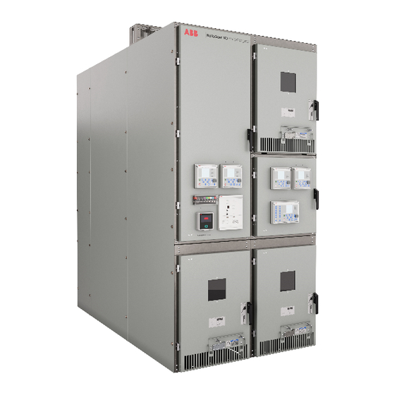
ANSI MEDIUM VOLTAGE METAL- CL AD DIGITAL SWITCHGEAR — ANSI medium voltage metal-clad digital switchgear — ANSI medium voltage (MV) metal-clad digital The traditional method of commissioning activity 01 ReliaGear ND MV switchgear is a new solution implemented in a... -
Page 7: Ethernet Network Verification
C O M M I S S I O N I N G A N D T E S T I N G G U I D E — Ethernet network verification — The Ethernet network interconnects protection • Network topology setting: Check the network 02 IP address setting relays in a substation. - Page 8 ANSI MEDIUM VOLTAGE METAL- CL AD DIGITAL SWITCHGEAR — Notice: If both, Master and Backup In case of Grandmaster clock (Satellite NOTICE 04 PTP priority setting controlled clock) failure, it is necessary to have master clocks fails, the protection for Master clock...
-
Page 9: Managed Ethernet Switches
C O M M I S S I O N I N G A N D T E S T I N G G U I D E — Managed Ethernet switches — To create a reliable Ethernet network for IEC 08 MX Config –... - Page 10 ANSI MEDIUM VOLTAGE METAL- CL AD DIGITAL SWITCHGEAR — Once the switch is found and displayed in the 10 Search results showing the discovered properties dialog screen, click on the crystal ball. switch by MXconfig (Figure 11) — 11 Location of crystal ball —...
- Page 11 C O M M I S S I O N I N G A N D T E S T I N G G U I D E — After entering the correct account and password 13 IP Settings information, enter the IP settings under the IP information screen Selection menu.
- Page 12 ANSI MEDIUM VOLTAGE METAL- CL AD DIGITAL SWITCHGEAR — 15 Port configuration dialogue — 16 PTP Transparent clock Port dialog — Time settings The PTP profile must be enabled on all ports. The Peer to peer delay interval is definite for power It is recommended to set a transparent time with profile 1s.
- Page 13 C O M M I S S I O N I N G A N D T E S T I N G G U I D E — 17 Switching VLAN Global dialog — 18 Switching Global dialog — 19 Switching Global dialog —...
- Page 14 ANSI MEDIUM VOLTAGE METAL- CL AD DIGITAL SWITCHGEAR — 20 Redundancy protocol This concludes the Switching Settings (VLAN) network settings activities. Check the HSR parameters setting according to the Moxa User’s Manual or Instruction Manual. It PRP and HSR redundancy settings varies based on the network topology used.
-
Page 15: Interconnections
C O M M I S S I O N I N G A N D T E S T I N G G U I D E — Interconnections — Check the interconnection of network 21 Example of components (protection relays, managed Communication diagram Ethernet switches) according to drawings provided in the project documentation (for... - Page 16 ANSI MEDIUM VOLTAGE METAL- CL AD DIGITAL SWITCHGEAR — 22 Example of Interconnection Wiring Diagram — 23 Example of Plant Structure in PCM600 — Protection relay If the connection between the PCM600 and Check the connection status of protection relays protection relay is established, a green tick mark via PCM600.
- Page 17 C O M M I S S I O N I N G A N D T E S T I N G G U I D E — Network redundancy Check if No GOOSE / SMV alarm is reported by 24 GOOSE / SMV Check the availability of voltage measurements the receiver protection relays.
-
Page 18: Primary Testing-Current Sensors
ANSI MEDIUM VOLTAGE METAL- CL AD DIGITAL SWITCHGEAR — Primary testing-current sensors — All current and voltage sensors can remain 27 Primary test system connected to the bus during power frequency CPC 100 from Omicron (bus hipot) and secondary wire dielectric testing. - Page 19 These routine tests are made as per the below. These are specifically designed to be used requirements of the sensor standards IEC with ABB digital switchgear with sensors 60044-8 or IEC 61869-10. compliant to the IEC standards. There may be other similar devices available that The test value is 80 A which represents a rated could be used.
- Page 20 ANSI MEDIUM VOLTAGE METAL- CL AD DIGITAL SWITCHGEAR — — 28 Example of a Table 3: Zero-clamping limits current sensor label Function Zero-clamping limit — 29 Current sensor Three-phase current parameters measurement (CMMXU) 1% of nominal (In) Residual current measurement (RESCMMXU)
- Page 21 C O M M I S S I O N I N G A N D T E S T I N G G U I D E — • Step 3/5 30 Primary test setup In the cable compartments, connect the for current sensors when busbars and injection device to the cable sealing end of the...
- Page 22 ANSI MEDIUM VOLTAGE METAL- CL AD DIGITAL SWITCHGEAR — • Step 1/6 32 Example of a Verify sensor parameters set in the protection current sensor label relay with sensor rating plates found on the — sensors. These may be found on the circuit...
- Page 23 C O M M I S S I O N I N G A N D T E S T I N G G U I D E — Breakers installed but no main bus in the • Step 2/7 36 Example of a switchgear frame Move the circuit breaker into the connected...
- Page 24 ANSI MEDIUM VOLTAGE METAL- CL AD DIGITAL SWITCHGEAR — • Step 5/7 39 Measurements view Inject current equal to the application nominal current or equal to the maximal current supported by the primary testing device if the application nominal current is out of the device setting range.
-
Page 25: Primary Testing-Voltage Sensors
C O M M I S S I O N I N G A N D T E S T I N G G U I D E — Primary testing-voltage sensors Primary testing verifies the whole measurement Multiply the ratio correction factor (ref. Step 1/7 chain including the sensor, cable connections and below) by the actual output voltage. - Page 26 ANSI MEDIUM VOLTAGE METAL- CL AD DIGITAL SWITCHGEAR — Voltage sensor installed in the cable The test setup to measure the secondary output 40 Example of a compartment of the sensors is shown below. EESAILEC test voltage sensor label socket pt#TC-E-RJ45-INF and RJ45 plug, pt#FI- —...
- Page 27 C O M M I S S I O N I N G A N D T E S T I N G G U I D E • Step 2/7 Since the protection relay is reporting phase-to- phase voltages, two identical measurements will Warning: Ensure that all equipment is de- appear on the display.
- Page 28 ANSI MEDIUM VOLTAGE METAL- CL AD DIGITAL SWITCHGEAR — • Step 7/8 46 Test setup for • Step 2/8 Inject voltage higher than 1% of the primary voltage sensors installed on main bus (nominal) value. Caution: Make sure there is no CAUTION —...
-
Page 29: Apparatus Control Testing
Breaker Commissioning Manual, document VAB (0.0)kV — #1VAL0501-MB, for the breakers provided in the VBC (0.0)kV 51 Single line diagram, switchgear. The IOMM documents for MV ANSI VCA (0.0)kV the circuit breaker is in the intermediate Digital Switchgear are: 3P=(0)kW... - Page 30 ANSI MEDIUM VOLTAGE METAL- CL AD DIGITAL SWITCHGEAR — • Step 2/10 IA (0)A 52 Single line diagram, IB (0)A Close the circuit breaker in the feeder to be the circuit breaker is closed and in the IC (0)A tested. Check the circuit breaker status on the service position IG (0.0)A...
- Page 31 C O M M I S S I O N I N G A N D T E S T I N G G U I D E — • Step 5/10 • Step 7/10 57 Activating On the protection relay LHMI (tested feeder) go Check the interlocking logic.
- Page 32 ANSI MEDIUM VOLTAGE METAL- CL AD DIGITAL SWITCHGEAR — Logic zone selective interlocking 60 Logic scheme of the When used in protection schemes, logic zone Logic busbar protection selective interlocking scheme selectively trips the — circuit breaker according to the logic scheme. The...
- Page 33 C O M M I S S I O N I N G A N D T E S T I N G G U I D E — • Step 5/10 • Step 7/10 64 Activating On the protection relay LHMI (upstream circuit On the protection relay LHMI (upstream circuit blocking mode breaker) go to ->...
-
Page 34: Secondary Testing Of Protection Relays
ANSI MEDIUM VOLTAGE METAL- CL AD DIGITAL SWITCHGEAR — Secondary testing of protection relays — In comparison with traditional switchgear, the 68 Changing correction overall testing procedure of protection relays has factors for amplitude not changed. Protection and metering functions —... -
Page 35: Ft-14D Flexitest Switch
C O M M I S S I O N I N G A N D T E S T I N G G U I D E — FT-14D Flexitest switch — FT-14D digital test switches are used for efficient FT-14D test switch 70 Typical FT-14D testing of protection and control relay during... - Page 36 ANSI MEDIUM VOLTAGE METAL- CL AD DIGITAL SWITCHGEAR — • Step 1/3 The switch blades are closed during normal 72 Low Voltage operation. For testing, the switch blades are Connect the FT-14D test harness RJ45 Compartment door of SafeGear with FT-14D opened to access the switch jaw.
- Page 37 CMLIB REF6xx 76 Linear current sensor instead of the PC with corresponding software which brings used to connect ABB’s Relion® 615/620 series Rogowski setting in additional functionality to the end user. The fitted with combined sensor inputs. The testing...
- Page 38 ANSI MEDIUM VOLTAGE METAL- CL AD DIGITAL SWITCHGEAR — Test Setup for Omicron – 1 phase • Step 2/3 77 1 phase test setup For high setting of Overcurrent protection, you Omicron tester is connected via connecting for the Omicron tester may need to apply at max.
- Page 39 FREJA 546 (Low Level Output Hardware option) is interconnected with a Low-level test adapter. The test adapter provides the interface between ABB’s Relion® 615/620 series fitted with combined sensor inputs and the tester. The test adapter is usually connected to the protection relay through FT-14D test switches via connecting shielded cables terminated with RJ45 connectors.
- Page 40 ANSI MEDIUM VOLTAGE METAL- CL AD DIGITAL SWITCHGEAR — Test Setup for Megger – 1 phase • Step 2/3 83 1 phase test setup For high setting of overcurrent protection, you Megger tester is connected via connecting for the Megger tester may need to apply at max.
- Page 41 C O M M I S S I O N I N G A N D T E S T I N G G U I D E — 86 Setting of high voltage analog outputs in the Megger configuration program —...
-
Page 42: Recommended Troubleshooting Tools
ANSI MEDIUM VOLTAGE METAL- CL AD DIGITAL SWITCHGEAR — Recommended troubleshooting tools — ITT600 SA Synthesizer The ITT SA Synthesizer provides a Single Line 89 ITT SA Synthesizer The ITT SA Synthesizer is a toolbox for testing Diagram like a SCADA display that displays the... - Page 43 C O M M I S S I O N I N G A N D T E S T I N G G U I D E — A possible system setup is shown in Figure 90. ITT600 SA Explorer tool offers facilities for 91 The main use cases The real IEDs are set up to control the typical bays exploring and analyzing the communication...
- Page 44 ANSI MEDIUM VOLTAGE METAL- CL AD DIGITAL SWITCHGEAR — 92 One IED on each side is selected to be compared — 93 Red indicates that configuration revision check is fine — 94 indicates that the check failed — 95 Bad quality of signals...
- Page 45 C O M M I S S I O N I N G A N D T E S T I N G G U I D E — Local HMI of 640 series PCM600 Online Monitoring Tool 98 Test and The LHMI supports the engineer during the relay’s commissioning support in the local HMI...
-
Page 46: Glossary
ANSI MEDIUM VOLTAGE METAL- CL AD DIGITAL SWITCHGEAR — Glossary 615 series Relion® 615 series protection and control relays 620 series Relion® 620 series protection and control relays 640 series Relion® 640 series protection and control relays Application Configuration Tool... - Page 48 The information contained in this document is for general information purposes only. While ABB strives to keep the information up to date and correct, it makes no representations or warranties of any kind, express or implied, about the completeness, accuracy, reliability,...