
Related Manuals for Piezoconcept HS1


Summary of Contents for Piezoconcept HS1
- Page 1 INSTALLATION AND OPERATION MANUAL PIEZOCONCEPT 15 Rue du Bocage 69008 LYON France...
- Page 2 Before disconnecting the DB-9 connector from the PIEZOCONCEPT controller, first set the command voltage to 0.0V, then turn the AC power to the PIEZOCONCEPT controller off, and finally wait one minute before disconnecting. The HS1 has no user serviceable parts. Only trained service personnel should perform service.
- Page 3 Unpacking the HS1 ..........................4 Handling the HS1..........................4 HS1............................... 5 INSTALLATION ............................5 Installing a single axis HS1 unit......................5 Installing a two axis HS1 unit ......................6 Installing a three axis HS1 unit ......................6 GROUND LOOPS ............................7 Prevention and identification of ground loops .................
- Page 4 • Do not lift by the cable. • The surface to which the HS1 is mounted to should be flat and clean. Likewise, the bottom of the HS1 should be free of particles and dust before mounting. • Do not immerse in any liquid. If the HS1 requires cleaning slightly dampen a lint free cloth with iso-propanol or ethanol and lightly wipe the surface.
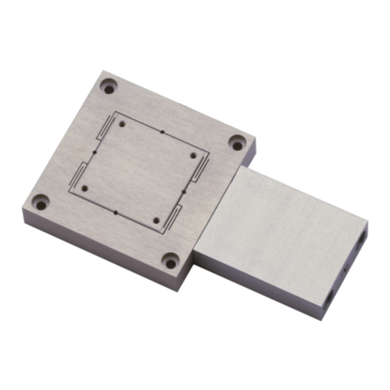
- Page 5 These M2.5 holes are on a 29mm square. To attach an item to the scanning stage, use the following procedure. • Using a lint free cloth, gently wipe off the top of the HS1 to remove any particles or dust. •...
- Page 6 1. Install the first or bottom HS1 (Y-axis) using the procedures described above in Section 2.1. 2. Using a lint free cloth, gently wipe off the top of the installed HS1 and the bottom of the adapter plate to remove any particles or dust.
- Page 7 The single greatest danger to your nanopositioning system is a ground loop between the stage and the mounting surface. Ground loops can be the source of noise in the HS1, and in some cases the oscillations may be severe enough to permanently damage the piezoactuators.
- Page 8 “PIEZOCONCEPT CONTROLLER OPERATION MANUAL”. 4.2 Care during operation The HS1 is a high precision scientific instrument and should be handled with care during operation. Failure to do so may result in permanent damage. During operation ensure that there are no physical constraints on the moving stage or anything fixtured to the moving stage.
Need help?
Do you have a question about the HS1 and is the answer not in the manual?
Questions and answers