Table of Contents
Advertisement
Quick Links
Operation Manual
Installation Manual
Operation Manual
Maintenance Manual
Specifications & References
AIR LEAK TESTER
LS-R700
No.LS-R700-941B1-D
Installation
Manual
Operation
Manual
Maintenance
Manual
Specifications
&
References
1
Introduction
2
Installation
3
Interface
4
Basic Operations
5
Screen List
6
Setup
Operations
7
Listed by Purpose
8
Interface
9
Troubleshooting
10
Specifications
11
Reference
Advertisement
Table of Contents
Troubleshooting

Related Manuals for Cosmo LS-R700

Summary of Contents for Cosmo LS-R700
- Page 1 Operation Manual Introduction Installation Manual Installation Manual Installation Operation Manual Maintenance Manual Specifications & References Interface AIR LEAK TESTER LS-R700 Basic Operations Operation Manual Screen List Setup Operations Listed by Purpose Interface Maintenance Manual Troubleshooting Specifications Specifications & References Reference...
-
Page 3: Table Of Contents
Rear Panel ............................14 Operation Keys ..........................15 Installation ............................16 Environment of Leak Tester and Leak Test Stand .................16 Installation of LS-R700 with Quick Mounting Brackets ..............16 Pneumatic Hookups ........................18 Tubing for Tested part (Work) and Master ..................20 Power Source ..........................20 Control I/O Connector ........................21 Turning on Power for the First Time ....................22... - Page 4 Table of Contents PERATION ANUAL Basic Touch Screen Operations ................41 Turn On Power ..........................42 Go to Sub Menus and Items ......................42 Go Back to the Previous Page ....................... 42 Switch Pages ........................... 42 Settings Lock / Unlock ........................43 Lock / Unlock Settings ........................
- Page 5 Table of Contents Error Log ............................63 I/O Monitor ............................63 Inspection ............................63 Calibration Reminder ........................64 Inspection Items ..........................64 Language Menu ..........................64 Troubleshooting Menu ........................64 10.1 Error List ............................65 10.2 Large Leak List ..........................65 10.3 Frequent (+) Fails ...........................65 10.4 Frequent (-) Fails ..........................65 Misc.
- Page 6 Table of Contents Analyze Measured Data ........................90 Use X-Chart ........................... 90 Backup and Restore ........................91 Restoring Test Parameters ......................91 Preparing for Replacing LS-R700 ....................92 Other Settings ..........................93 Name Channels ..........................93 Other Features ..........................94 10.1 Backlight Auto-off ...........................
- Page 7 Table of Contents AINTENANCE ANUAL Maintenance ....................... 97 Daily Inspection Points ........................98 Monthly Inspection Points ......................98 Annual Inspection Points ........................99 Features for Maintenance........................99 K(Ve) Check ............................99 No-Leak Check ..........................100 DPS Offset Adjustment ........................ 100 DPS Span Check ......................... 101 PS Offset Adjustment ........................
- Page 8 Table of Contents PECIFICATIONS EFERENCE 0 Specifications ......................127 Primary Specifications ........................128 Model Classifications........................129 1 Reference ........................131 Leak Testing Overview ........................132 Stage Summary ........................... 132 Internal Pressure Changes of the WORK And MASTER ............133 Leak Rate Conversion ......................... 133 External Appearance ........................
-
Page 9: Introduction
1 Introduction NSTALLATION ANUAL NTRODUCTION 1 Introduction ......................8 2 Safety Precautions ....................8 3 Notes ......................... 9... -
Page 10: Introduction
1 Introduction Thank you for purchasing the Air Leak Tester LS-R700 Series. LS-R700 is a differential pressure decay air leak tester designed for industrial use. This manual provides installation, operating and maintenance instructions for LS-R700 Series. Read this operation manual carefully before using this product, and retain it for future reference. -
Page 11: Notes
The user is encouraged to consult your local Cosmo representative directly for any questions regarding the use of this product. -
Page 13: Installation And Setup
Operation Keys ......................15 3 Installation ......................16 Environment of Leak Tester and Leak Test Stand ............16 Installation of LS-R700 with Quick Mounting Brackets ..........16 Pneumatic Hookups..................... 18 Tubing for Tested part (Work) and Master ..............20 Power Source ......................20 Control I/O Connector .................... -
Page 14: Unpacking
2 Installation and Setup When you receive the LS-R700, unpack and check for the transport damage. 1.1 Accessories Power cord Control I/O connector: MSTB 2,5 / 16-STF-5,08 (Phoenix Contact) Inspection record / Traceability related documents 1 each Operation manual CD (Installation manual / Operation manual / Maintenance manual / Specifications &... -
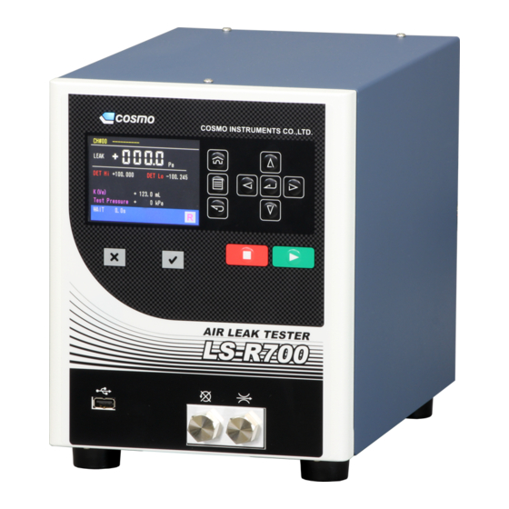
Page 15: Part Identifications
Software can be upgraded using this port. Operation keys ■ key: Used to stop a measurement in manual mode. ► key: Used to start a measurement in manual mode. Quick Mounting Bracket: Using this bracket, LS-R700 can be installed and removed easily with two M4 screws. -
Page 16: Rear Panel
100-240VAC~50/60Hz 100VA MAX.1ph COM1 BYPASS FILL WORK EXHAUST MASTER COSMO INSTURUMENTS CO., LTD MADE IN JAPAN CONTROL I/O (Phoenix contact): WORK: External device is connected to control WORK-side stop valve LS-R700 externally. A port to connect a tested part (Work). -
Page 17: Operation Keys
2 Installation 2.3 Operation Keys Home key: Used to open a measurement screen programmed to be the Home screen. Menu key: Used to open the main menu Back key: Used to back to the previous screen. Enter key: Used to complete the selection or numeric entry. Cursor keys: Used to move the cursor within a page or program numbers. -
Page 18: Installation
Mounting Base This base is loosely attached to the bottom of LS-R700. Remove it from the tester and mount it on the leak test stand where LS-R700 is to be mounted with four M4 screws. The mounting surface has to be flat and smooth. - Page 19 2 Installation How to Mount Two mounting brackets are attached to the bottom of the LS-R700, A in front and B in back. Mounting Bracket A Mounting Bracket B Mounting Base Mount as the following procedure: Mount the “Mounting Base” on...
-
Page 20: Pneumatic Hookups
100-240VAC~50/60Hz 100VA MAX.1ph Pilot pressure Regulated between 400 and 700kPa. COM1 BYPASS FILL WORK EXHAUST MASTER COSMO INSTURUMENTS CO., LTD MADE IN JAPAN Master Chamber Tested Part (Sold Separately) Optional Equipment Connection Air Dryer Bypass Circuit Unit Drain Test Pressure T2.5A–250V... - Page 21 When using an oil lubricated vacuum pump: A solenoid valve which opens to atmosphere should be used to prevent oil from entering the LS-R700 when the pump is turned off. The tester should also be installed at a higher level than the vacuum pump.
-
Page 22: Tubing For Tested Part (Work) And Master
3.4 Tubing for Tested part (Work) and Master Select tubes considering the follows: Cosmo recommends rigid nylon tubes that does not expand by air pressure. • The higher the test pressure is, the thicker the tubes should be, and the larger the part volume is, the larger the tube diameter should be. -
Page 23: Control I/O Connector
2 Installation 3.6 Control I/O Connector The control I/O port interfaces the LS-R700 to an external devices such as PLC. CAUTION Electric Shock Be sure to turn off the main power before wiring. • A twisted pair cable preferably with shield should be used and should be separated from the power line. -
Page 24: Turning On Power For The First Time
> Press to complete selection > > Enter > LS-R700 will reboot in the selected language. The programmed Home screen will be displayed(The default is Standard Measurement Screen) Press on the Home screen to open the Main Menu Screen. -
Page 25: Interface
3 Interface NTERFACE 1 Control I/O Port ...................... 24 Standard Control I/O Port: Phoenix Contact .............. 24 Control I/O Port D-SUB Connector (Special Spec.) ..........25 Input Specifications ...................... 26 Output Specifications ....................26 Typical PLC Connection ....................28 Channel Code ......................29 Stage Number Output .................... -
Page 26: Control I/O Port
3 Interface The control I/O port interfaces LS-R700 to an external device with the capabilities to control and receive the test results remotely. This port allows the tester to be integrated into a completely automated line. 1.1 Standard Control I/O Port: Phoenix Contact... -
Page 27: Control I/O Port D-Sub Connector (Special Spec.)
3 Interface 1.2 Control I/O Port D-SUB Connector (Special Spec.) Connector Model Leak Tester Side: XM3C-3722 (OMRON) Cable Side: XM3D-3721 (OMRON) Connector Pin Assignments Soldered side (NO: Normally Open / NC: Normally Close) Pin# Function Type Pin# Function Type Reserved CH# 4 *2 Input NO START... -
Page 28: Input Specifications
3 Interface 1.3 Input Specifications Photocoupler diode input Input impedance: 3 KΩ Input current: 10 mA typ. (24 VDC) Wiring Input Circuit Photocoupler D-SUB Standard (Special spec.) Connection 1A - 6A 2 - 7 Pin# A 9A - 13A 20 - 24 External Power Pin# B Air Leak Tester... - Page 29 3 Interface Protection of Output Load When using the output induction load (such as relay, monitor etc), please arrange the diode for protection. NPN Connection Diode for protection Output External power PNP Connection Diode for protection Output External power D-SUB Standard (Special spec.) Pin# A...
-
Page 30: Typical Plc Connection
3 Interface 1.5 Typical PLC Connection NPN-type input/output circuit configuration of LS-R700 PC output card External power input External power PC input card +24V Photo MOS relay D-SUB Standard (Special spec.) Pin# A Pin# B Pin# C Pin# D Pin# E... -
Page 31: Channel Code
3 Interface 1.6 Channel Code Pins 9A through 13A (For D-SUB, pins 20 through 24) are used for switching channel automatically by external device. Channel can be changed by entering BCD codes to those pins. Pin 9A (For D-SUB, pin 20) is the most significant bit (MSB) and Pin 13A (For D-SUB, pin 24) is the least significant bit (LSB). -
Page 32: Signal Timing Charts
3 Interface 1.8 Signal Timing Charts Leak Test Timing Chart WAIT PCHK BAL1 BAL2 WAIT 100ms(MIN.) 300ms(MIN.) CH# *1 400ms(MIN.) START 300ms(MAX.) BUSY "1""2"or"3" "0" "2" STAGE # "1" "3" "0" for Fail only JUDGMENT *2 ERROR CH # includes CH #, K(Ve) CHECK, MASTERING / DRIFT CLR, and Calibration Valve Open/Close signals. JUDGMENT includes PASS, UL FAIL, LL FAIL, UL2 FAIL AND LL2 FAIL signals. -
Page 33: Checking Wiring With I/O Monitor
3 Interface Charge Hold Timing Chart WAIT/DL1/CHG/BAL1/DL2/BAL2/DET WAIT 100ms(MIN.) 300ms(MIN.) CH# (Remote) *1 CHG HOLD (Remote) 300ms(MAX.) 300ms(MAX.) "0""1""2"or"3" "1" STAGE# "0" BUSY CHG HOLD (Manual) STOP (Manual) CH # is acceptable in the WAIT stage, but not in any other stage. 1.9 Checking Wiring with I/O Monitor This can be used to check if the wire connection to external devices is correct. -
Page 34: Rs-232C Serial Interface Port
(NULL-MODEM mode direct connections). Through this port, the LS-R700 transmits leak test data after every test execution. The Leak Tester does not accept any commands from the host; it only transmits leak test data. -
Page 35: Formats Of Rs-232C Output
3 Interface 2.3 Formats of RS-232C Output Data output is available from the RS-232C port on the rear panel. The LS-R700 supports nine(9) output formats. For selecting a format, go to: System > System Settings > RS-232C > Format T Format... - Page 36 3 Interface ID Format (Default format) #zz_00_J_±LLL.LLL_±AAA.AAA_±BBB.BBB_±DDD.DDD_±PPP.PPP_±EEE.EEE_±FFF.FFF_CC:GG CR Data field Data type Unit Min. Max. Note Tester ID 2-digit decimal 1: LL FAIL 2: Pass ASCII code 4: UL FAIL Result 9: LL2 FAIL (1-digit hexadecimal) C: UL2 FAIL D: Error Leak Fixed point Leak unit...
- Page 37 Error Code R 4-digit hexadecimal Date YYYY-MM-DD Time HH:MM:SS Checksum G 2-digit hexadecimal Codes for errors and Corresponding Errors of LS-R700 Code Error Description 8000 Error: 1 PS Offset Error 4000 Error: 11 ~ 16 Air Operated Valve Error 0800...
- Page 38 3 Interface M Format #zz_CC_RR_J_±LLL.LLL_±PPP.PPP_±DDD.DDD_±KKK.KKK_HHH.H_III.I_www.w_NNN.N_OOO.O_QQQ.Q_vvv.v_S SS.S_TTT.T_UUU.U_VVV.V_WWW.W_xxx.x_ll_pp_kk_±ccc.ccc_±ddd.ddd_±hhh.hhh_±aaa.aaa_±bbb.bbb_±iii.iii_±EE E.EEE_±FFF.FFF_e_ff_gg_jj_±mmm.mmm_±nnn.nnn_±ooo.ooo_±qqq.qqq_±rrr.rrr_±sss.sss_tt_uu_±YYY.YYY_±ZZZ. ZZZ_YYMMDD_HHMMSS:GG CR Data field Data type Unit Min. Max. Note Tester ID 2-digit decimal 2-digit decimal Error code 2-digit decimal 1: LL FAIL 2: Pass One ASCII code 4: UL FAIL Result 9: LL2 FAIL (1-digit hexadecimal) C: UL2 FAIL D: Error...
- Page 39 + 999.999 Date YYMMDD Time HHMMSS Checksum 2-digit hexadecimal Codes for errors and Corresponding Errors of LS-R700 Code Error Description Not Error (Pass/Fail) Error: 23 Mastering Error Error: 52 SPI2_res Error: 22 Stop Valves Closed Error: 1 PS Offset Error...
-
Page 40: Checksum
Use a printer that can print 80 characters or more in one line, and that can print character fonts. Also, use a cable whose length is 3 m or shorter. Recommended Printer: DPU-414 series (Seiko) Printer Cable Wiring Change settings for the printer to the follows: DPU414 LS-R700 9 pin CR: Carriage Return 9 pin Baud Rate: 9600 (bps) RD(RxD) - Page 41 3 Interface Result Symbols in Leak Test Data Print Out and D Format Result Symbol Description Pass CHG NG , CHG -NG CHG Large Leak BAL1 +NG Insufficient Test Pressure detected by PS (TP LL) UL NG , LL NG Exceeding UL or LL in BAL2 UL NG , LL NG Exceeding UL or LL in DET...
-
Page 42: Usb Port
• FU22048E1BP2TO-I-MS-111-STD 2GB virus infection via USB Memories. What data can be stored or copied to USB Memory from LS-R700 • Parameters in one file (CSV copy to USB) in Settings Menu • Live Test Data Recording (Test Data, Waveform Data, Mastering Data) in System Menu •... -
Page 43: Basic Touch Screen Operations
4 Basic Touch Screen Operations PERATION ANUAL ASIC OUCH CREEN PERATIONS 1 Turn On Power ....................... 42 2 Go to Sub Menus and Items ................. 42 3 Go Back to the Previous Page ................42 4 Switch Pages ......................42 5 Settings Lock / Unlock .................. -
Page 44: Turn On Power
4 Basic Touch Screen Operations Turn on the power with the power switch on the rear panel. Home screen will be displayed on the LCD (Default is Standard measurement screen). Let the power on for 5 minutes or longer for a warm-up before starting leak tests. All sub menus are accessible from the Main Menu, which consists of 2 pages. -
Page 45: Settings Lock / Unlock
4 Basic Touch Screen Operations Pages can be switched also with right/left cursor key. Unlocking the settings enables settings change. (Settings cannot be changed when it’s locked) Move the cursor to the pad lock icon on the Main menu and press Lock menu includes Settings Unlock, Settings Lock and Passcode. -
Page 46: Set A Passcode
4 Basic Touch Screen Operations 5.2 Set a Passcode A passcode of your choice (4-digit number) can be set. Default is 0000. Unlock the settings in the Lock Menu first, then After Unlocking settings, go to: Select Passcode Setting > Press to enable programming. -
Page 47: Go To Main Menu
4 Basic Touch Screen Operations Press to go to the Main Menu. 9.1 Change channels Press to move the cursor to CH# and press Press to select a channel with and press CH#00 to CH#31 9.2 Select an Option From Multiple Selections Press to move the cursor to an Item and press Press... -
Page 49: Screen List
5 Screen List CREEN 1 Main Menu ............48 6 Comp. (Compensation) Menu ......60 Mastering Settings ..........60 2 Measurement Screen Menu ......48 Mastering Display ..........61 Measurement Screens (Remote) ...... 48 Drift Comp Settings..........61 Measurement Screen Description: Standard Drift Comp Display .......... -
Page 50: Main Menu
5 Screen List This is the main menu. All sub menus are accessible from this screen. Main Menu Measure Screen Troubleshooting Misc. Settings System K(Ve) Comp. R / M Analysis Maint. Language There are 3 measurement screens, Standard, Advanced and Waveform, which can be switched while a test is in progress. -
Page 51: Measurement Screen Description: Standard (Manual)
5 Screen List 2.2 Measurement Screen Description: Standard (Manual) Usually manual mode measurement is performed for initial test parameter settings. Unlock Settings and toggle the operation mode to Manual. Standard screen is a simple display with the test pressure, leak and Pass/Fail judgment. CH#: Channel number and title Mode: Up to 20 letters are allowed for the channel... -
Page 52: Measurement Screen Description: Advanced (Manual)
5 Screen List 2.3 Measurement Screen Description: Advanced (Manual) Leak: Leak in a selected unit Comp: Current compensation value TP LL / TP UL: K(Ve): The current K(Ve) value Upper and lower limits for test pressure Test Pressure: Test pressure in a selected unit DET LL / DET UL: Upper and lower limits for leak in Detection stage. -
Page 53: Settings Menu
5 Screen List Menu to set the leak test parameters. Settings Basic Settings Advanced Settings Common Settings Copy Settings Initialize to Default Backup/Restore CSV Copy to USB 3.1 Basic Settings Minimum settings for leak test. Setting these items enables a simple leak test. Timer Pressurization (CHG) Basic Settings... -
Page 54: Advanced Setting
5 Screen List Pressurization (CHG) Equalization (BAL1) Timer 0 to 999.9 [s] Stabilization (BAL2) Detection (DET) Pressure Unit kPa, MPa (PSI, kg/cm , bar, mbar, mmHg, cmHg, inHg) *1 Pressure Setting Pressure applied to tested part (WORK) and reference part (MASTER) Test Pressure Upper Press Limit... - Page 55 5 Screen List Leak Limit BAL2 UL BAL2 LL DET UL2 DET UL DET LL DET LL2 NR Iterations Refer to 3.5. CHG Options Precharge Timer (PCHG) Refer to 2.2. Pre-exhaust Timer (PEXH) Precharge Settings Precharge Upper Limit Precharge Lower Limit Bypass Valve Precharge Iterations Self Check...
-
Page 56: Common Settings
Disable/Enable Bypass Circuit Unit is sold separately. Precharge Iterations 1 to 20 Overall Self Check Disable/Enable Blow ΔP Limit Check the pneumatic circuit of LS-R700 Self Check Idle ΔP Check Timer Check the fill valve during idle state. Idle ΔP Check Limit 3.3 Common Settings... -
Page 57: Copy Settings
5 Screen List 3.4 Copy Settings Test parameters of a channel can be copied to other channels. “ ” Refer to for the details. PERATIONS ISTED BY URPOSE 3.5 Initialize to Default Default settings are copied to the channels of your choice. “... -
Page 58: System Menu
5 Screen List Menu to program the start-up settings, calendar feature and data output and to perform System Backup/Restore. System System Settings Data to Store in USB Test Data Update Time System Backup/Restore 4.1 System Settings Menu to set Start-up conditions, Date and Time and RS-232C Start-up Start-up Mode Select System Settings... -
Page 59: Data To Store In Usb
5 Screen List Start-up Mode Select Remote / Manual Home Screen Select Selectable: Standard, Advanced, Waveform LCD backlight goes off if no operation key is touched for the programmed Backlight Auto-off period. Start-up Disable, 1, 5, 10, 30, 60, 120, 240 [mins] Select the position of decimal point in the leak rate to be displayed from 0, Decimal Point Position 0.0, 0.00, and 0.000. -
Page 60: Ve) Menu
5 Screen List LS-R700 computes leakage based on the measurement of the pressure difference between the non-leaking master and the tested part. K(Ve) is "leak coefficient" which is used for converting measured differential pressure into a flow rate. This menu is to program the settings and carrying out the Automatic K(Ve) Setup. -
Page 61: K(Ve) Automatic Setup
Program K(Ve) Check Limit in percentage (%) before performing K(Ve) Check. LS-R700 compares K(Ve) measured with a known good part to the K(Ve) stored in memory. An error is displayed if the difference exceeds the tolerance. This can be used for daily sensitivity checks. -
Page 62: Comp. (Compensation) Menu
5 Screen List Comp. Mastering Settings Mastering Display Drift Comp Settings Drift Comp Display Fixed Comp Settings 6.1 Mastering Settings Basic Settings Mastering Comp Mastering Settings Refer to “ PERATIONS MB1 Timer ” ISTED BY URPOSE for the details. MB2 Timer Mastering Iterations M. -
Page 63: Mastering Display
5 Screen List 6.2 Mastering Display Displays up to 20 DET data. The display can be toggled between the table (List) and bar graph(Graph). 6.3 Drift Comp Settings Drift Comp Drift Comp Settings Refer to “ ” PERATIONS ISTED BY URPOSE Number of Samples for the details. -
Page 64: Analysis Menu
ISTED BY URPOSE Go to this menu for LS-R700 maintenance such as Battery Replacement and Inspection as well as viewing error log and I/O Monitor. The person use the menu must be the person who is in charge of Maintenance of LS-R700. -
Page 65: Battery Replacement
MPa (PSI, kg/cm , bar, mbar, mmHg, cmHg, inHg) *1 Leak Check No Leak Check Perform a No-Leak Check of LS-R700 itself. Sensor Adjust DPS offset and check the span Adjust PS offset and check the span E/P Regulator Adjust E/P regulator The units in ( ) are not available for SI unit restriction models. -
Page 66: Calibration Reminder
5 Screen List 8.5 Calibration Reminder Menu to set the recalibration reminder by entering the date the inspection and calibration were performed and how many months the calibration is good for. A message will pop up 1 month before the “Recalibration Target”. The Recalibration Target can be set up to 36 months from the date of inspection. -
Page 67: Error List
5 Screen List 10.1 Error List Displays the probable causes and treatments for Errors. “ ” Refer to for the details. ROUBLESHOOTING 10.2 Large Leak List Displays the probable causes and treatments for Large Leaks. “ ” Refer to for the details. ROUBLESHOOTING 10.3 Frequent (+) Fails... -
Page 69: Setup
6 Setup ETUP 1 Initial Setups ......................68 Operation Mode when the power turns on ..............68 Home Screen ....................... 68 Set Date........................68 Set Time ........................68 2 Perform a Simple Air Leak Test ................69 Test Parameter Entry ....................69 Timer ........................... -
Page 70: Initial Setups
6 Setup This section provides the required Initial setups before using LS-R700 Attention Settings unlock is required to change settings and toggling to Manual (M) mode to execute a measurement manually. 1.1 Operation Mode when the power turns on Select a operation mode when the power is turned on from Remote (R) or Manual (M) Go to: >... -
Page 71: Perform A Simple Air Leak Test
Set the parameters according to your test specifications. Pressure limits are for monitoring the applied pressure during the Pressurization stage to detect large leak. Besides, if a large leak occurs in the system, LS-R700 can detects it before tester proceeds to Stabilization (BAL2) and Detection (DET) stages. -
Page 72: Leak Limit
6 Setup 2.4 Leak Limit Set the parameters according to your test specifications. Select a leak unit Enter Detection (UL). Enter Detection (LL). 2.5 K(Ve) Enter K(Ve) Unit and Value if they are determined. Select a K(Ve) unit. Enter K(Ve) value. -
Page 73: Flow For Initial Adjustment
6 Setup LS-R700 computes leakage based on the measurement of the pressure difference between the non-leaking master and the tested part. K(Ve) is "leak coefficient" which is used for converting measured differential pressure into a flow rate. Condition Check Determine the following conditions before the initial adjustment. - Page 74 6 Setup Not Leaking 3. Check whether there are deformation factors. Yes --- Check ---- If the clamp force is appropriate. If the machine is leveled. Hardness of sealing material If there is a stopper If the tested part itself deforms. No --- Go to the next item to check.
-
Page 75: Initial Test Parameter Backup
6 Setup Please perform the system backup after all the test parameters are entered and setup is completed. NOTE The backup data is only for restore the test system and cannot be viewed in computers. 4.1 System Backup Perform System backup to prepare for restoring the test system in case of trouble in the future. System Restore “... -
Page 76: Notation Of Air Leak Tests Stages And Limits
6 Setup Symbols are used for Leak test stages and Limits as follows: Stage Symbol Limit Display Idol state WAIT Stabilization Upper Limit BAL2 (UL) Charge Delay Stabilization Lower Limit BAL2 (LL) PCHK PCHK Detection Upper Limit 2 DET (UL2) Precharge PCHG Detection Upper Limit... -
Page 77: Operations Listed By Purposes
Backup and Restore ........91 Enhance Test Result Reliability ....81 Restoring Test Parameters ......... 91 Setting Mastering Compensation ....... 81 Preparing for Replacing LS-R700 ...... 92 Setting Drift Compensation ........ 81 Other Settings ..........93 Setting Fixed Compensation ......82 Name Channels .......... -
Page 78: Display Measured Differential Pressure In A Leak Rate Unit
Obtain K(Ve) value through K(Ve) Automatic Setup or manually calculate and enter K(Ve) value. LS-R700 computes leakage based on the measurement of the pressure difference between the non-leaking master and the tested part. K(Ve) is "leak coefficient" which is used for converting measured differential pressure into a flow rate. - Page 79 ► > > K(Ve) > K(Ve) Automatic Setup > After 3 phases of tests, LS-R700 will show the K(Ve) value. Change the Leak Unit to a Flow rate unit. > Main Menu >Settings > Advanced Settings > Unit > Leak Unit...
-
Page 80: Manual Entry Of K(Ve) Value (Leak Coefficient)
7 Operations Listed By Purposes 1.2 Manual Entry of K(Ve) Value (Leak Coefficient) Manually enter the calculated K(Ve) > Main Menu > K(Ve) > K(Ve) Settings > Basic Settings > K(Ve) Value What to do • Use Mastering Compensation • Use Bypass Circuit Unit (Option) 2.1 Setting Mastering Compensation The measured pressure change in a leak test typically contains both the true leakage and drift errors due to... - Page 81 7 Operations Listed By Purposes Mode > Meas Mode > Mastering Start Mastering Value Sampling > Check the Mastering graph > Main Menu > Comp > Mastering Display > Graph 10) An ideal Mastering graph shows DET data gradually decreases and becomes constant close to 0.
-
Page 82: Bypass Charge (Option)
7 Operations Listed By Purposes When to execute a Mastering Value Sampling A Mastering Value Sampling must be executed when the test parameters change, environmental conditions change, or the drift portion shifts significantly. • Beginning of the first shift At the beginning of the morning shift (when the machine is turned on) it is expected that environmental conditions will be significantly different from those at the time when the last Mastering was performed on the previous working day. -
Page 83: Enhance Test Result Reliability
7 Operations Listed By Purposes What to do • Use Mastering Compensation • Use Drift Compensation • Use Fixed Compensation • Use Mastering and Drift Compensation together • Use Noise Reduction • Use Exhaust Interference Prevention feature 3.1 Setting Mastering Compensation Refer to 2.1 Setting Mastering Compensation for the details. -
Page 84: Setting Fixed Compensation
7 Operations Listed By Purposes 3.3 Setting Fixed Compensation Fixed Compensation is used when environmental conditions are stable. It is recommended to use after verifying the environmental conditions are stable using Drift Compensation feature. Enter a compensation value which is subtracted from the measured data. The feature is disable as default. -
Page 85: Setting Exhaust Interference Prevention
7 Operations Listed By Purposes LS-R700 permits setting another sets of leak limits for DET stage, DET(UL2) and DET(LL2) which are called Noise Reduction (NR) limits, besides DET(UL) and DET(LL) limits. The ranges between those two sets of limits are considered as uncertain judgment regions. While NR feature is enabled, NR process automatically starts right after the normal leak test cycle when a measured leak data in DET stage falls in the uncertain judgment region. -
Page 86: Enhance Test Reliability
Set Idle ΔP Check • 4.1 Setting Idle ΔP Check (Self Check) LS-R700 checks if fill valve is closed during idle state. > Main Menu > Settings > Advanced Settings > Self Check > Idle ΔP Check Timer > Idle ΔP Check Limit What to do •... -
Page 87: Collecting Data In Usb Memory
Viewing The Stored Data in USB Pull out the USB memory from LS-R700 and connect it to your computer. All the data is in CSV format Data is automatically named by the date and time and stored in each folder sorted by channels. - Page 88 Name of file: YYYYMMDD_HH_CH#XX.csv Year Month Date_Hour_Channel#.csv ig: 20130723_00_CH#00.csv ( _ represents a space) Pass: Removable Disc\LS-R700\AUTO SAVE\LEAK DATA\ YYYYMMDD_HH_CH#XX.csv Example: FILE NAME LSR700\AUTO SAVE\LEAK DATA\CH#00\20130723 00 CH#00.csv BAL Leak DET Leak Comp ValuMastering DPS Raw Test Press Judgment Mode...
-
Page 89: Copy Test Parameters To Ubs Memory
Waveform Data: A new file is created every 1 hour. • Mastering Data: A new file is created once a month Copying the Test logs in the internal memory of LS-R700 to USB Refer to 7.1 Use X-Chart 5.3 Copy Test Parameters to UBS Memory The currently programmed test parameters can be copied in one csv file to USB memory. - Page 90 7 Operations Listed By Purposes The file can be viewed in a computer. All the test parameters are listed by channels. The Folder and Files The backup data is stored in a folder “CsvSet” that is automatically created inLS-R700 folder. The file name is the date and time the file was created (YYYYMMDDHHMM.csv) Pass: Removable Disc\LSR700\CsvSet\YYYYMMDDHHMM.csv...
-
Page 91: Programming Parameters For The Similar Tested Parts
7 Operations Listed By Purposes What to do • Copy Settings • Initialize to Default 6.1 Copy Settings Test parameters of a channel can be copied to other channels. > Main Menu > Settings > Copy Settings Select a source channel Select destination channels More than one channels can be selected. -
Page 92: Analyze Measured Data
Use X-Chart to view daily trends and simple statistic of the test data 7.1 Use X-Chart LS-R700 stores up to 1000 test logs in all 32 channels. All the test logs in the channel of your choice are displayed in figures (oldest data at the top) or a chart (oldest data on the left). -
Page 93: Backup And Restore
• Restoring test parameters after changing them temporarily: Parameter Backup/Restore • Preparing for replacing LS-R700 for some trouble: System Backup and Restore System Backup/Restore There are two different types of Backup/Restore, System in the System Menu and Test Parameters in the Settings ... -
Page 94: Preparing For Replacing Ls-R700
The backup data can be restored only to itself. Individual Restore In Individual Restore, test parameters set to the LS-R700 can be copied to other LS-R700 testers. Items selected among the backup from the source tester can be restored individually to the destination tester. However, this feature requires full understanding that there are items that affect each other such as timers, leak limits and K(Ve) value. -
Page 95: Other Settings
Backup data can only be restored exactly the same models it was backed up from. Be sure to compare the model information on the front panel of the LS-R700 to ensure that they are identical. A2MRGK4.UX2 SERIAL No.000-00000000 MFG DAT E 2013-04 Model Information A2MRGK4.UX2... -
Page 96: Other Features
7 Operations Listed By Purposes 10.1 Backlight Auto-off The backlight of LS-R700 goes off automatically when any operation key is not touched for programmed period of time. > Main Menu > System > System Settings > Start-up > Backlight Auto-off > Select the duration... -
Page 97: K(Ve) Check
If test results are not relatively consistent. Normally extending Pressurization (CHG) timer or Equalization (BAL1) timer will help stabilize the pressure and consequently the test result will be consistent. LS-R700 can be updated by users. Please follow the procedure comes with the update file. -
Page 99: Maintenance
8 Maintenance AINTENANCE ANUAL AINTENANCE 1 Daily Inspection Points ..................98 2 Monthly Inspection Points ..................98 3 Annual Inspection Points ..................99 4 Features for Maintenance ..................99 K(Ve) Check ........................ 99 No-Leak Check ......................100 DPS Offset Adjustment ....................100 DPS Span Check ....................... -
Page 100: Daily Inspection Points
8 Maintenance Periodic Inspection and Calibration helps maintain the accuracy of LS-R700 and prevent malfunction Performing the following inspection is highly recommended. Attention Settings unlock is required to change settings and toggling to Manual (M) mode to execute a measurement manually. -
Page 101: Annual Inspection Points
8 Maintenance Contact your local Cosmo representative for scheduling Annual Calibration Service. The following items will be inspected and calibrated. Check the oil mist separator and the filter. Leak check of the leak tester Check the DPS offset. Check the DPS span Check the PS offset. -
Page 102: Leak Check
Timers are fixed to the follows: CHG=10.0s BAL1=0.5s BAL2=5.0s DET=10.0s LS-R700 is not leaking if the result is within ±10 Pa. If not, contact Cosmo for repair. ■ Press to stop Open the both WORK and MASTER side stop valves. -
Page 103: Dps Span Check
DPS readout will be displayed on the screen of LS-R700. not guarantee the calibrated value. 10) Compare the readouts displayed on LS-R700 and displayed on the calibration equipment. 4.5 PS Offset Adjustment > Main Menu > Maint. > Inspection > Sensor > PS Check whether the sensor is open to the atmosphere. -
Page 104: Battery Replacement
LS-R700 Internal Memory (SRAM) LS-R700 buffers memory with a battery. Memory includes calendar, Compensation V (Man), Mastering Value (Man), Counter, X-Chart/List, Error Log, which cannot be used once battery is discharged completely. - Page 105 Make sure not to touch unnecessary parts power connector of LS-R700. when removing the top cover. Touching Unscrew the two screws on the top of LS-R700 (Rear side unnecessary parts may cause lowering the performance of LS-R700 and Front side) to remove the top cover.
-
Page 106: About Error 51: Lo Battery Sram
> Time Set the current date and time. 5.2 About ERROR 51: Lo Battery SRAM All measurements are disabled if the error occurs. Please replace the battery immediately. The following data in LS-R700 will be wrong. • Date and Time •... -
Page 107: How To Troubleshoot Error 51
5.4 If ERROR 51 Occurs Right After Replacing Battery If the error occurred right after replacing battery, some internal electrical part may be malfunctioned. Contact Cosmo for repair after executing System Backup. > Main Menu > System > Backup/Restore > Backup Items cleared by Memory Clear •... -
Page 109: Troubleshooting
9 Troubleshooting ROUBLESHOOTING 1 When an Error Occurred ...................... 108 2 Error List ..........................108 3 Error Messages and Treatments ..................109 ERROR 1 PS Offset Error ......................109 ERROR 2 PS Out of Range ..................... 109 ERROR 3 Test Pressure Error....................110 ERROR 4 BAL1 Lost Test Pressure ..................111 ERROR 10 DPS Offset Error ....................111 ERROR 11 Air Operated Valve Error 1 .................. -
Page 110: When An Error Occurred
9 Troubleshooting The error code is displayed when an error occurs. Check the description of the error in Error List Menu to view descriptions, probable causes and treatments and all the errors. > Main Menu > Troubleshooting > Error List The errors are divided every 9 codes. -
Page 111: Error Messages And Treatments
Adjust the PS offset. tolerance when the power is turned on. Go to: Maint. > Inspection > Sensor > PS(P1) Contact Cosmo for repair if the offset exceeds ±2% of the sensor range. ▼ During power-on check procedure Output Signal Timing Chart... -
Page 112: Error 3 Test Pressure Error
Fluctuation or a drop in the source pressure Check the source pressure or the regulator setting. Avoid using air tools branching off the pressure source of the LS-R700 to supply an stable air. Setting up a dedicated pressure source for the LS-R700 is recommended. -
Page 113: Error 4 Bal1 Lost Test Pressure
Fluctuation or wrong setting of the pilot pressure Adjust the pilot pressure between 400kPa and 700 kPa. Avoid using air tools branching off the pressure source of the LS-R700 to supply an stable air. Setting up a dedicated pressure source for the LS-R700 is recommended. -
Page 114: Error 11 Air Operated Valve Error 1
Pilot pressure is not stable or the regulator is not Adjust the pilot pressure between 400kPa and 700 kPa. adjusted properly. Avoid using air tools branching off the pressure source of the LS-R700 to supply an stable air. Setting up a dedicated pressure source for the LS-R700 is recommended. -
Page 115: Error 12 Air Operated Valve Error 2
Pilot pressure fluctuates or the pressure setting is Adjust the pilot pressure between 400kPa and 700 kPa. inappropriate. Avoid using air tools branching off the pressure source of the LS-R700 to supply an stable air. Setting up a dedicated pressure source for the LS-R700 is recommended. -
Page 116: Error 14 Air Operated Valve Error 4
Adjust the pilot pressure between 400kPa and 700 kPa. pressure setting is inappropriate. Avoid using air tools branching off the pressure source of the LS-R700 to supply an stable air. Setting up a dedicated pressure source for the LS-R700 is recommended. -
Page 117: Error 15 Air Operated Valve Error 5
Pilot pressure fluctuates or the pressure setting is Adjust the pilot pressure between 400kPa and 700 kPa. inappropriate. Avoid using air tools branching off the pressure source of the LS-R700 to supply an stable air. Setting up a dedicated pressure source for the LS-R700 is recommended. -
Page 118: Error 16 Air Operated Valve Error 6
Adjust DPS offset LS-R700 is in idle state. Go to: Maint. > Inspection > Sensor > DPS Contact Cosmo for repair if the DPS offset exceeds ±30% of its range. Extend Idle ΔP Check Timer or Exhaust timer. Exhaust time is insufficient. -
Page 119: Error 21 Dps Stopped Oscillating
3.11 ERROR 21 DPS Stopped Oscillating Timing: Always monitored Criteria: DPS stopped oscillating. Probable Cause Treatment Malfunction of the DPS or power source or cable Contact Cosmo for repair. disconnection ▼ During power-on check procedure Output Signal Timing Chart PIN# Function TYPE WAIT... -
Page 120: Error 23 Mastering Error
9 Troubleshooting 3.13 ERROR 23 Mastering Error Timing: At the end of the last iteration of DET for Mastering value sampling Criteria: Leak data at the end of the last DET iteration exceeded the Mastering Limit in the Mastering Sampling. Probable Cause Treatment Pressurization and stabilization time... -
Page 121: Error 24 K(Ve) Value Out Of Range
9 Troubleshooting 3.14 ERROR 24 K(Ve) Value Out of Range Timing: The last DET in K(Ve) Automatic Setup Criteria: Calculated K(Ve) exceeded 100L. Probable Cause Treatment The current K(Ve) settings does not match the Check the settings for the calibrator. calibrator used for K(Ve) Automatic Setup causing Go to: K(Ve) >... -
Page 122: Error 51~Error 61 System Errors
(8 Maintenance). Probable Cause 2 If the same error occurs after replacing the battery, some electrical parts may be malfunctioned. Treatment 2 Contact Cosmo for repair after executing a System Backup ERROR 52 SPI2_res AD Communication failure ERROR 53... -
Page 123: Large Leak List
If the problem persists without identifiable causes, please conduct the No Leak Check. Close both the WORK and MASTER stop valves on the rear panel of the tester. Go to: >Main Menu > Maint. > Inspection > Leak Check > No-Leak Check Contact Cosmo for repair, if internal leak is found. -
Page 124: Output Signal Timing Charts For Large Leak Timing
9 Troubleshooting 4.1 Output Signal Timing Charts for Large Leak Timing ▼ CHG Large Leak WORK side PIN# Function TYPE WAIT DL1 PCHK PCHG PEXH CHG END WAIT Standard D-SUB STAGE #0 STAGE #1 ERROR PASS UL FAIL BUSY LL2 FAIL LL FAIL UL2 FAIL ▼... - Page 125 9 Troubleshooting Output Signal Timing Charts ▼ DL2 Large Leak WORK side PIN# Function TYPE WAIT DL1 PCHK PCHG PEXH CHG BAL1 END WAIT Standard D-SUB UL FAIL LL2 FAIL LL FAIL UL2 FAIL ▼ DL2 Large Leak MASTER side PIN# Function TYPE WAIT...
-
Page 126: Frequent (+) Fails
Perform a No-Leak Check with the stop valves on the rear panel closed. If the LS-R700 is not leaking, the cause of the frequent fails is something else. Proceed to the next item to check. Contact Cosmo for repair if internal leak is found. - Page 127 9 Troubleshooting Check the condition of the tested parts. Probable Cause Treatment Part temperature is higher or lower Let the part temperature be ambient by adding a cooling/warming buffer in than the ambient temperature. the production line. The tested parts are wet. Improve the drying process or add one if there isn't any.
-
Page 128: Frequent (+) Fails
Perform a No-Leak Check with the stop valves on the rear panel closed. If the LS-R700 is not leaking, the cause of the frequent fails is something else. Proceed to the next item to check. Contact Cosmo for repair if internal leak is found. -
Page 129: Specifications
10 Specifications PECIFICATIONS EFERENCE PECIFICATIONS 1 Primary Specifications ..................128 2 Model Classifications ..................129... - Page 130 10 Specifications Differential Resolution: 0.1 Pa Pressure Display Range: ±999 Pa Accuracy Guaranteed Range: ±1000 Pa Sensor Sensor Range: ±2000 Pa (Standard) Sensor Proof Pressure: 5 MPa Reading Accuracy: ±2.5% of rdg ±1Pa 50Pa or lower: ±2Pa *1 Test Pressure Reading Accuracy: ±1% of F.S.
- Page 131 10 Specifications LS-R700-A B C A: Pneumatic Circuit Intelligent 1 Pneumatic Circuit Large flow circuit with great sensor protection features Intelligent 2 Pneumatic Circuit Equipped an equalization valve and additional self-check features to A1 circuit For the parts whose volume is approx. 10 mL or smaller and the leak...
-
Page 133: Reference
11 Reference EFERENCE 1 Leak Testing Overview ..................132 Stage Summary ......................132 Internal Pressure Changes of the WORK And MASTER ........... 133 Leak Rate Conversion ....................133 2 External Appearance ................... 135 3 Pneumatic Circuit ....................136 4 Pressure Unit Conversion Table ................ 138 5 Flow Unit Conversion Table ................ -
Page 134: Leak Testing Overview
11 Reference After a non-leaking reference part (MASTER) and a tested part (WORK) are pressurized simultaneously, isolating the MASTER and WORK from the pressure source, and the differential pressure sensor (DPS) measure the pressure drop resulting by leaks. 1.1 Stage Summary Stages Start After clamping and sealing a WORK, initiates a start signal. -
Page 135: Internal Pressure Changes Of The Work And Master
11 Reference 1.2 Internal Pressure Changes of the WORK And MASTER The figure on the right shows the pressure changes inside CHG and BAL1 BAL2 DET the WORK and the MASTER. Pressure change using non-leaking part and master Pressure change Valve using leaking part closed... - Page 136 Volumetric leak rate [mL/min] × Pressure drop due to leaks [Pa] Ve: Equivalent internal volume [mL] Detection time(s) The LS-R700 uses the above equation to calculate the leak rate. Note that the tester uses standard atmospheric pressure for this calculation.
-
Page 137: External Appearance
11 Reference... -
Page 138: Pneumatic Circuit
11 Reference NOTE The actual circuit may not be same as the drawing. A2: (M: Medium Pressure / L: Low Pressure) OPTION R MASTER PRESSURE EXHAUST SOURCE WORK 400kPa G3 PILOT PILOT PRESSURE PORT PRESSURE OPTION J PCHK PCHG PEXH CHG BAL1 BAL2 DET BLOW EXH... - Page 139 11 Reference A2: (V: Vacuum Pressure) PRESSURE SOURCE MASTER WORK 400kPa PILOT PRESSURE PCHK PCHG PEXH CHG BAL1 BAL2 DET BLOW EXH *SV8 *SV8 is for K(Ve) Automatic Setup and K(Ve) Check.
-
Page 140: Pressure Unit Conversion Table
11 Reference 1kg/cm2→ 0.980665 14.2233 735.55914 28.959 393.7 10000 98.0665 0.0980665 980.665 0.96784 ←1bar→ 1.0197162 14.50373 750.06158 29.529962 401.46227 10197.162 1000 0.9869221 ←1psi→ 0.0703072 0.0689478 51.715083 2.0360254 27.679934 703.07172 6.8947783 0.0068948 68.947783 0.0680461 ←1mmHg→ 0.0013595 0.0013332 0.0193367 0.0393701 0.5352391 13.5951 0.1333224 0.0001333 1.3332239... -
Page 141: Ce Marking
”EC Declaration of Conformity” to prove the product complies with the provisions of the European Directive is available upon request. Changes or modifications not expressly approved by Cosmo could void the user’s authority to operate the equipment. (excluding particular specifications) This equipment has been tested and found to comply with the limits for Class A digital device, pursuant to part 15 of the FCC Rules. -
Page 142: Common Peripherals
Installing an External Exhaust Valve between air leak tester and tested part prevent the contamination. External Exhaust Valve G3-ME MASTER LS-R700 WORK G3-ME 9.2 Bypass Circuit Unit Test time can be reduced by using a Bypass Circuit Unit when testing tested parts with a large internal volume with low test pressure because it fills the parts with air in a short period of time. - Page 143 JAKARTA, INDONESIA FAX: +62-(0)21-42900044 VIETNAM COSMOWAVE TECHNOLOGY CO.,LTD. PHONE: +84-(0)47876085 VIETNAM REPRESENTATIVE OFFICE FAX: +84-(0)47876084 INDIA COSMO INSTRUMENTS INDIA PVT. LTD. HEAD OFFICE PHONE: +91-(0)124-421-0946 GURGAON, INDIA FAX: +91-(0)124-411-5926 COSMO INSTRUMENTS INDIA PVT. LTD. PHONE: +91-(0)8032559254 SOUTH ZONE REGIONA OFFICE Bangalore TEX EQUIPAMENTOS ELETRONICOS IND.
- Page 144 * The specifications are subject to change without notice. http://www.cosmo-k.co.jp/ 2974-23 ISHIKAWA HACHIOJI, TOKYO 192-0032 JAPAN COSMO INSTRUMENTS CO., LTD. PHONE: +81-(0)42-642-1357 FAX: +81-(0)42-646-2439...
Need help?
Do you have a question about the LS-R700 and is the answer not in the manual?
Questions and answers