Table of Contents
Advertisement
Available languages
Available languages
allen + roth and logo design are trademarks or
registered trademarks of LF, LLC.
All rights reserved.
Serial Number:
Questions, problems, missing parts? Before returning to your retailer, call our
customer service department at 1-866-439-9800, 8 a.m. - 8 p.m., EST,
Monday - Sunday. You could also contact us at partsplus@lowes.com or visit
www.lowespartsplus.com.
AS21004
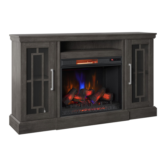
ELECTRIC FIREPLACE TV STAND
Purchase Date:
MODEL #144723/28MMP7409-PG77
ITEM #3730313
Español p. 23
Advertisement
Chapters
Table of Contents

Related Manuals for Allen + Roth 144723


Summary of Contents for Allen + Roth 144723
- Page 1 ITEM #3730313 ELECTRIC FIREPLACE TV STAND MODEL #144723/28MMP7409-PG77 Español p. 23 allen + roth and logo design are trademarks or registered trademarks of LF, LLC. All rights reserved. Serial Number: Purchase Date: Questions, problems, missing parts? Before returning to your retailer, call our customer service department at 1-866-439-9800, 8 a.m.
-
Page 2: Table Of Contents
TABLE OF CONTENTS Product Specifications .......................2 Safety Information......................3 Maximum Load........................5 Package Contents......................6 Hardware Contents......................7 Preparation.........................8 Assembly Instructions......................8 Operating Instructions......................14 Troubleshooting.......................16 FCC/IC Information......................18 Care and Maintenance.....................18 Warranty...........................19 Battery Replacement......................20 Replacement Parts List....................21 PRODUCT SPECIFICATIONS VOLTAGE 120VAC, 60 Hz AMPS 12.5 Amps WATTS 1500 Watts 28MMP7409REV1.0... -
Page 3: Safety Information
SAFETY INFORMATION When using electrical appliances, basic precautions should always be followed to reduce the risk of fire, electrical shock, and injury to persons including the following: 1. Read all instructions before using this appliance. 2. DANGER – High temperatures may be generated under certain abnormal conditions. - Page 4 Fig.1 13. This appliance, when installed, must be electrically grounded in accordance with local codes or, in the absence of local codes, with the current CSA C22.1 Canadian Electrical Code or for U.S.A. installations, follow local codes and the National Electrical Code, ANSI/NFPA NO.70. 14.
-
Page 5: Maximum Load
MAXIMUM LOAD MAXIMUM LOAD 13.6 kg / 30 lb MAXIMUM LOAD 27.3 kg / 60 lb MAXIMUM LOAD 6.8 kg / 15 lb MAXIMUM LOAD 9.1 kg / 20 lb WARNING Loads heavier than the maximum weights specified may result in instability, causing tip over resulting in death or serious injury. -
Page 6: Package Contents
PACKAGE CONTENTS PART DESCRIPTION QUANTITY Base Center Shelf Left Inside Panel Right Inside Panel Left Side Panel Right Side Panel Mantel Top Back Side Panels Center Back Panel Left Door Right Door Adjustable Shelf Electric Fireplace Insert Remote 28MMP7409REV1.0 23MMP3101REV1.0... -
Page 7: Hardware Contents
HARDWARE CONTENTS M3x19mm M3x12mm M4x50mm M3x12mm Back Panel Bracket Screw Screw Screw Screw Qty:16 Qty:16 Qty: 8 Qty: 2 Qty: 2 M3.5x15mm Tipping Restraint Hardware USB Output Euro Hinge Handle Screw Qty: 1 Qty: 4 Qty: 1 Qty: 8 Qty: 2 M4x15mm Metal Panel Bracket Shelf Pin... -
Page 8: Preparation
PREPARATION Before beginning assembly of product, make sure all parts are present. Compare parts with package contents list and hardware contents list. If any part is missing or damaged, do not at- tempt to assemble, install or operate the product. To protect the product from possible scratch- es, please assemble the parts on a scratch-free surface. - Page 9 ASSEMBLY INSTRUCTIONS 3. Attaching the side panels • Locate the Left and Right Side Panels (E and F). • Align the Left and Right Side Panels (E and F) with the Base. • Insert Screws (CC) through the Base and into the pre-drilled holes on the edges of the Left and Right Side Panels (E and F) as shown.
- Page 10 ASSEMBLY INSTRUCTIONS 6. Attaching the back panels • Locate the Back Side Panels (H) and the Center Back Panel (I). • Slide the Back Side Panels (H) into the grooves between the inner and outer side panels as shown. Slide all the way down until the Back Side Panels (H) meet the bottom shelf.
- Page 11 ASSEMBLY INSTRUCTIONS 9. Preparing the doors • Locate the Left Door (J) and Right Door (K). • Secure Euro Hinges (GG) to the Left Door (J) using Screws (II) on both the upper and lower hinge as indicated. • Repeat steps on the Right Door (K). Hardware Used Euro Hinge M3.5x15mm...
- Page 12 ASSEMBLY INSTRUCTIONS 12. Inserting the adjustable shelves • Locate the two Adjustable Shelves (L). • Insert the Shelf Pins (KK) into the pre-drilled holes on the inside of each cabinet side panel at your desired height. Align all pins to the same height to ensure your shelf is level.
- Page 13 ASSEMBLY INSTRUCTIONS 15. Installing the tip restraint hardware • When the Tipping Restraint Hardware (HH) is properly installed, it can provide protection against unexpected tipping of the Unit due to small tremors, bumps or climbing. • Each Tipping Restraint Hardware (HH) includes one Unit Anchor, one Wall Anchor, one Anchor Tether, and four Anchor Screws.
-
Page 14: Operating Instructions
OPERATING INSTRUCTIONS CONTROL PANEL LOCATION ICON FUNCTION DESCRIPTION There are 5 brightness levels that can be selected FLAME and OFF (00) setting. Settings F5 - F1 decrease in brightness. Press the heater button on the control panel to turn HEATER on/off (00) and adjust the heater setting. - Page 15 OPERATING INSTRUCTIONS ICON FUNCTION DESCRIPTION Pressing the timer button will cycle through the TIMER timer settings: 30 minutes, 1 Hour, 2H, 3H, 4H, 5H, 6H, 7H, 8H, 9H and OFF (00). The flame speed is only adjustable from the FLAME SPEED remote control.
-
Page 16: Troubleshooting
TROUBLESHOOTING PROBLEM POSSIBLE CAUSE CORRECTIVE ACTION Unplug the fireplace, remove the back panel of the fireplace and check that The thermostat sensor is the thermostat is plugged into the main Display shows “ ” broken or disconnected. circuit board. If this does not solve the problem contact customer service for a replacement thermostat sensor. - Page 17 TROUBLESHOOTING PROBLEM POSSIBLE CAUSE CORRECTIVE ACTION Thermostat setting is Adjust the temperature settings to Heater does not blow preventing heater from ensure that the thermostat is set higher warm air. turning on. than the current room temperature. Flame effect works but heat- With the power on press and hold the er function does not and the POWER button on the control panel for...
-
Page 18: Fcc/Ic Information
FCC/IC INFORMATION Warning: Changes or modifications to this unit not expressly approved by the party responsible for compliance could void user’s authority to operate the equipment. NOTE: This equipment has been tested and found to comply with the limits for Class B digital device, pursuant to part 15 of the FCC Rules. -
Page 19: Warranty
1-YEAR LIMITED WARRANTY The manufacturer warrants that your new Electric Fireplace is free from manufacturing and material defects for a period of one year from date of purchase, subject to the following conditions and limitations. Install and operate this appliance in accordance with the installation and operating instructions furnished with the product at all times. -
Page 20: Battery Replacement
REPLACING THE REMOTE CONTROL BATTERIES: NOTE: Battery disposal Please always dispose of batteries at a suitable recycling point. NOTE: Do not mix old and new batteries. Do not mix alkaline, standard (carbon zinc), or rechargeable (nicad, ni-mh, etc.) batteries. CAUTION: •... -
Page 21: Replacement Parts List
REPLACEMENT PARTS LIST For replacement parts, call our customer service department at 1-866-439-9800, 8 a.m. - 8 p.m., EST, Monday - Sunday. You could also contact us at partsplus@lowes.com or visit www.lowespartsplus.com. PART PART NAME PART NUMBER Floor glide PH-GLDBRW001 Metal Plate PH-PLTBRZ001 Flame Circuit Board... - Page 22 Printed in China allen + roth and logo design are trademarks or registered trademarks of LF, LLC. All rights reserved. 28MMP7409REV1.0 23MMP3101REV1.0...
- Page 23 ARTÍCULO #3730313 BASE PARA TELEVISOR CON CHIMENEA ELÉCTRICA MODELO #144723/28MMP7409-PG77 allen + roth y el diseño del logotipo son marcas Español p. 23 comerciales o marcas registradas de LF, LLC. Todos los derechos reservados. Número de serie: fecha de compra: ¿Preguntas, problemas, piezas faltantes? Antes de volver a la tienda, llame...
-
Page 24: Especificaciones Del Producto
ÍNDICE Especificaciones del producto ....................24 Información de seguridad......................25 Carga Máxima.........................28 Contenido del paquete......................29 Aditamentos..........................30 Preparación..........................31 Instrucciones de ensamblaje....................31 Instrucciones de funcionamiento.....................37 Solución de problemas......................39 Información sobre la FCC/IC....................41 Cuidado y mantenimiento......................41 Garantía...........................42 Reemplazo de la batería......................43 Lista de piezas de repuesto.....................44 ESPECIFICACIONES DEL PRODUCTO VOLTAJE 120VAC, 60 Hz... -
Page 25: Información De Seguridad
INFORMACIÓN DE SEGURIDAD Cuando utilice electrodomésticos eléctricos, siempre tome medidas de precaución básicas para evitar incendios, descargas eléctricas y lesiones personales. Entre las medidas: 1. Lea todas las instrucciones antes de usar este electrodoméstico. 2. PELIGRO: se pueden generar altas temperaturas debido a ciertas condiciones que no son normales. - Page 26 12.Conecte solo a tomacorrientes con la debida puesta a tierra. Este calentador se diseñó para su uso en 120 voltios. El cable tiene un enchufe como se muestra en A de la Fig. 1. No use adaptadores de 2 clavijas. Nunca lo use con extensiones eléctricas ni tomacorrientes de alimentación reubicables (tomacorrientes múltiples o regletas).
- Page 27 18.Este calentador puede incluir una alarma visual que emite una advertencia si sus piezas están excesivamente calientes. Si la alarma parpadea, apague el calentador inmediatamente e inspeccione si hay objetos sobre o junto a este que puedan causar altas temperaturas. NO PONGA EN FUNCIONAMIENTO EL CALENTADOR CON LA ALARMA ACTIVADA.
-
Page 28: Carga Máxima
CARGA MÁXIMA CARGA MÁXIMA 13.6 kg / 30 lb CARGA MÁXIMA 27.3 kg / 60 lb CARGA MÁXIMA 6.8 kg / 15 lb CARGA MÁXIMA 9.1 kg / 20 lb PRECAUCIÓN Cargas mayores que los pesos máximos especificados puede generar inestabilidad y, en consecuencia, desplomes que pueden causar la muerte o lesiones graves. -
Page 29: Contenido Del Paquete
CONTENIDO DEL PAQUETE PIEZA DESCRIPCIÓN CANTIDAD Base Repisa central Panel interior izquierdo Panel interior derecho Panel lateral izquierdo Panel lateral derecho Parte superior de la repisa para chimenea Paneles laterales posteriores Panel posterior central Puerta izquierda Puerta derecha Repisa ajustable Accesorio para chimenea eléctrica Control remoto 28MMP7409REV1.0... -
Page 30: Aditamentos
ADITAMENTOS Tornillo Tornillo Soporte del Tornillo Tornillo M3x19 mm M3x12 mm panel posterior M4x50 mm M3x12 mm Cant.: 16 Cant.: 2 Cant.: 16 Cant.: 2 Cant.: 8 Aditamento de Tornillo Bisagra Euro contención antivuelcos Salida USB Manija M3,5x15 mm Cant.: 4 Cant.: 1 Cant.: 1 Cant.: 2... -
Page 31: Preparación
PREPARACIÓN Antes de comenzar a ensamblar el producto, asegúrese de tener todas las piezas. Compare las piezas con la lista del contenido del paquete y la lista de aditamentos. No intente en- samblar, instalar ni utilizar el producto si falta alguna pieza o si estas están dañadas. Para proteger el producto de posibles rayones, ensamble las piezas sobre una superficie que no produzca rayones Tiempo estimado de ensamblaje: 30 minutos... - Page 32 INSTRUCCIONES DE ENSAMBLAJE 3. Colocación de los paneles laterales • Ubique los paneles laterales izquierdo y derecho (E y F). • Alinee los paneles laterales izquierdo y derecho (E y F) con la base. • Inserte tornillos (CC) a través de la base y en los orificios pretaladrados en los bordes de los paneles laterales izquierdo y derecho (E y F), como se muestra.
- Page 33 INSTRUCCIONES DE ENSAMBLAJE 6. Colocación de los paneles posteriores • Ubique los paneles laterales posteriores (H) y el panel posterior central (I). • Deslice los paneles laterales posteriores (H) en las ranuras entre los paneles laterales interior y exterior, como se muestra. Deslice com- pletamente hacia bajo hasta que los paneles laterales posteriores (H) se unan con el estante inferior.
- Page 34 INSTRUCCIONES DE ENSAMBLAJE 9. Preparación de las puertas • Ubique la puerta izquierda (J) y la puerta derecha (K). • Asegure las bisagras Euro (GG) a la puerta izquierda (J) con los tornillos (II) tanto en la bisagra superior como en la inferior, como se indica.
- Page 35 INSTRUCCIONES DE ENSAMBLAJE 12. Inserción de los estantes ajustables • Ubique los dos estantes ajustables (L). • Inserte los pasadores para estantes (KK) en los orificios pretaladrados en el interior de cada panel lateral del gabinete a la altura deseada. Alinee los pasadores a la misma altura para garantizar que el estante está...
- Page 36 INSTRUCCIONES DE ENSAMBLAJE 15. Instalación de los aditamentos de contención antivuelcos • Cuando los aditamentos de contención antivuel- cos (HH) se instalan correctamente, pueden proporcionar protección contra vuelcos inesper- ados de la unidad debido a pequeños temblores, golpes o subidas. •...
-
Page 37: Instrucciones De Funcionamiento
INSTRUCCIONES DE FUNCIONAMIENTO UBICACIÓN DEL PANEL DE CONTROL ICONO FUNCIÓN DESCRIPCIÓN Hay 5 niveles de brillo que se pueden seleccionar, LLAMA además del ajuste OFF (Apagado) (00). Los ajustes F5 a F1 disminuyen en brillo. Presione el botón del calentador en el panel de CALENTADOR control para encender o apagar (00) y ajustar la configuración del calentador. - Page 38 INSTRUCCIONES DE FUNCIONAMIENTO ICONO FUNCIÓN DESCRIPCIÓN Al presionar el botón del temporizador se alternará TEMPORIZADOR entre los ajustes del temporizador: 30 minutos, 1 hora, 2 h, 3 h, 4 h, 5 h, 6 h, 7 h, 8 h, 9 h y APAGADO (00).
-
Page 39: Solución De Problemas
SOLUCIÓN DE PROBLEMAS PROBLEMA CAUSA POSIBLE ACCIÓN CORRECTIVA Desenchufe la chimenea, retire el pa- nel posterior de la chimenea y revise El sensor del termostato que el termostato esté enchufado en La pantalla muestra “ ” está roto o desconec- la placa del circuito principal. - Page 40 SOLUCIÓN DE PROBLEMAS PROBLEMA CAUSA POSIBLE ACCIÓN CORRECTIVA El funcionamiento normal continuará en ejecución por menos de un minuto El calentador no emite aire antes de apagarse. Los tiempos Tiempo de enfriamiento. caliente. variarán dependiendo de las temperaturas. Durante este tiempo soplará...
-
Page 41: Información Sobre La Fcc/Ic
INFORMACIÓN SOBRE LA FCC/IC Advertencia: los cambios o las modificaciones a esta unidad que no estén expresamente aprobados por la parte responsable del cumplimiento podrían anular la autorización del usuario para utilizar el equipo. NOTA: este equipo ha sido probado y se ha verificado que cumple con los límites para un dispositivo digital clase B, conforme a la sección 15 de las regulaciones de la FCC. -
Page 42: Garantía
1 AÑO DE GARANTÍA LIMITADA El fabricante garantiza que su nueva chimenea eléctrica no presentará defectos de fabricación ni en los materiales durante un período de un año a partir de la fecha de compra, siempre y cuando se cumplan las siguientes condiciones y limitaciones. Este electrodoméstico se debe instalar y operar en todo momento de acuerdo con las instrucciones de instalación y operación proporcionadas con el producto. -
Page 43: Reemplazo De La Batería
CÓMO REEMPLAZAR LAS BATERÍAS DEL CONTROL REMOTO: NOTA: eliminación de las baterías Siempre elimine las baterías en un punto de reciclaje adecuado. NOTA: no mezcle baterías viejas con nuevas. No mezcle baterías alcalinas con baterías estándar (carbono-cinc) o recargables (níquel- cadmio, níquel-hidruro metálico, etc.). -
Page 44: Lista De Piezas De Repuesto
LISTA DE PIEZAS DE REPUESTO Para obtener piezas de repuesto, llame a nuestro Departamento de Servicio al Cliente al 1-866-439-9800, de lunes a domingo de 8 a.m. a 8 p.m., hora estándar del Este. T ambién puede ponerse en contacto con nosotros en partsplus@lowes.com o visitar www.lowespartsplus.com. - Page 45 Impreso en China allen + roth y el diseño del logotipo son marcas comerciales o marcas registradas de LF, LLC. Todos los derechos reservados. 28MMP7409REV1.0 23MMP3101REV1.0...
- Page 46 28MMP7409REV1.0 23MMP3101REV1.0...
- Page 47 28MMP7409REV1.0 23MMP3101REV1.0...
Need help?
Do you have a question about the 144723 and is the answer not in the manual?
Questions and answers