Table of Contents
Advertisement
One World, One Home
Installation and Operation Manual of
Commercial Air Conditioner
This Manual applies to modular air-cooled (heat pump)
chiller units
Modle: CA0035EAND
CA0070EAND
CA0100EAND
CA0130EAND
Dear Haier users,
Thank you for selecting and using Haier products.
Haier provides products of excellent quality and good performance. For your convenience of use, please
read and follow this manual carefully. Haier's "international star-class service" is always available to you.
If you have any problem during operation, please contact with us byt telephone number or address on
the warranty. We are always at your service.
Haier – Sincere Forever!
The Haier modular air-cooled unit you purchased may not be fully consistent with this Manual due to
product improvement. We apologize for such inconvenience (if any) to you.
Notes to users:
Please pay attention to the following notes for the proper use and maintenance, more efficient operation
and longer service life of unit:
1.
This Manual includes information necessary for the proper installation, commissioning, startup and
maintenance, so please read it carefully before the startup or maintenance.
2.
Installation must be performed by trained professionals.
3.
For the first startup, please follow the steps herein to ensure personal and unit safety. The first
startup shall be carried out under the guidance of our professional commissioning personnel or
assigned personnel.
National standard applied:
Please read this Manual carefully before operation.
GB/T 18430.1-2007
Safekeep this Manual for future reference.
Advertisement
Table of Contents

Related Manuals for Haier CA0035EAND


Summary of Contents for Haier CA0035EAND
- Page 1 We are always at your service. Haier – Sincere Forever! The Haier modular air-cooled unit you purchased may not be fully consistent with this Manual due to product improvement. We apologize for such inconvenience (if any) to you.
- Page 2 We are always at your service. Haier – Sincere Forever! The Haier modular air-cooled unit you purchased may not be fully consistent with this Manual due to product improvement. We apologize for such inconvenience (if any) to you.
-
Page 3: Table Of Contents
Contents Product Introduction ........................... 1 Safety Precautions ........................... 2 Controller Operation Instruction ......................3-5 Installation ..............................6 Installation ............................6-13 Drawing of Overall Dimension ......................6 Unit Base Diagram ........................... 6-7 Pre-installation Preparation ......................... 8 Selection of Installation Position ...................... 8-10 Water Pipe Connection ........................ -
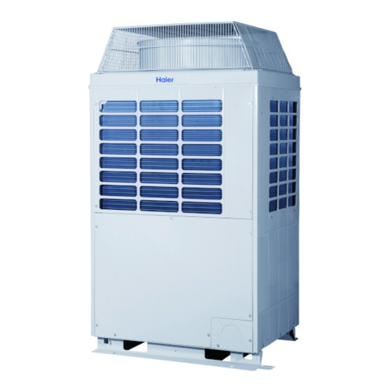
Page 4: Product Introduction
Product Introduction ■ Overview R410A-series modular air-cooled chiller unit is designed to satisfy users with the maximum reliability, safety and adaptability. The unit is well designed with aesthetic and elegant appearance. Additionally, with adaptable configuration, the unit can be connected to various specifications and types of fan coils or air handling units. -
Page 5: Safety Precautions
Safety Precautions ■ Symbol description ◆ Dear user, For the better understanding of this Manual and the proper operation of the chiller, the marks and symbols used in this Manual are described as follows: WARNING: it is likely to cause death, serious injury and other severe accidents if the user fails to do as required. -
Page 6: Controller Operation Instruction
Controller Operation Instruction ■ Description of controller panel ◆ Key description of wired controller [On/Off] key: this key is used for the system on/off control; if the initial status is “off”, and the system is started up when pressing this key once, and vice versa. During the startup, the LED indicator light (green) is on. - Page 7 Description of Basic Operation of Wired Controller Once powered on, the wired controller displays a startup password input interface; and the operation can be done only after the input of correct startup passwords. (please consult Haier’s after sales service personnel for initial passwords).
- Page 8 Controller Operation Instruction Press on the [Select] key to select the timing mode, the selected timing mode is displayed on a black background; press on the [Modify] key to switch among Week/Cycle/Day/Timing Disabled modes. Upon the completion of setting, press the [Exit] key to return to the previous interface, and the system completes the setting and adjustment of timing mode.
-
Page 9: Installation
A 10-20 mm rubber shock pad shall be placed between the unit and the base. The unit and the base may be fastened with ø16 or ø18 anchor bolts. Unit Base Diagram CA0035EAND Unit Base Diagram... - Page 10 CA0070EAND Water Outlet Water Inlet Electric control cabinet Draining Valve Unit Base Diagram ◆ CA0100EAND/CA0130EAND Unit Base Diagram ◆...
-
Page 11: Pre-Installation Preparation
Installation Pre-installation Preparation ◆ Cargo inspection All units are firmly bolted on wood trays, subject to ex-factory inspection and filled with accurate amount of R410a refrigerant and refrigeration oil for the unit operation. Upon the receipt, you shall carefully inspect cargoes for any damage during transport and confirm all ordered parts and accessories are delivered. - Page 12 Installation 1.Diagram of installation space for single chiller unit (Unit:mm) Guiding device 。 2.Diagram of installation space for multiple chiller units (Unit:mm) >450 >1500 >1500...
-
Page 14: Water Pipe Connection
Installation Water Pipe Connection External water pipe system must be equipped with flexible joints, water filter, electronic cleaner, check valve, drain valve, exhaust valve, shutoff valve, expansion tank, etc.. The expansion tank shall be located at 1-1.5 m above the highest point of the system; the exhaust valve shall be set between the highest point of the system and the expansion tank, and insulations shall be arranged between the tank and the pipe. -
Page 15: Electrical Connection
Installation SCHEMATIC DIAGRAM of WATER SYSTEM Symbol Symbol Description Description Fan co il Check valve Wate r pump A utomatic exhaust valve Flexible co nnection Water filter E xpansion tank Fan co il S top va lve Electronic water processor Fan co il Thermometer 3 -way valve... -
Page 16: Schematic Diagram Of Water System
Installation Electrical Connection Before circuit connection, following safety rules and measures must be adhered to: The unit must be installed by our service personnel or specially trained installation personnel. The installation shall be in accordance with applicable national and local laws, regulations and standards on electrical, building and environmental protection, etc., and requirements in the installation manual. -
Page 17: Overall Nozzle Dimensions During Module Combination
Installation Overall Nozzle Dimensions during Module Combination (Maximum 16 modules combined) Number of modules Overall nozzle dimensions (mm) -
Page 18: Calculations Of Water System Inventory
During unit operation, the actual operating capacity of the water system is less than the minimum water capacity required, resulting in frequent alarm and shutdown of the unit. Model of unit Preset return water temperature (℃) Minimum effective water capacity Vmin. (I) CA0035EAND CA0070EAND CA0100EAND CA0130EAND... -
Page 19: Electrical Connection
If the unit is not provided with end linkage control, LINE, 0V shall be short-circuited. Electrical parameters Reference cable Model of unit Rated current Maximum current Locked-rotor current sectional area 5X6 mm CA0035EAND 15.8A 27.5A 155A 5X10 mm CA0070EAND 34.6A (155X2)A CA0100EAND 53.2A... -
Page 20: Address Code Setting
Installation Address Code Setting ( SW401) The former four digits of the eight-digit code switch are for module address setting, and the latter four for unit mode and capacity setting. The unit mode and capacity codes have been set in delivery, and they are unchangeable. -
Page 21: Maintenance
Maintenance ■ Maintenance Before delivery, the units have been strictly tested and inspected to ensure good working performance after delivery. To ensure long-term good operation of the units, users shall provide regular maintenance. Inspection and cleaning of condenser To ensure effective operation of the condenser and maximize heat exchange, the appearance must be clean, and free from fallen leaves, cotton velvet, insects and other foreign matters which may result in clogged fin of the condenser. -
Page 22: Fault Code
Maintenance ■ Fault Code S/N Fault code Fault description Remarks Fault in flow switch √ Three-phase AC input phase failure protection Three-phase AC input phase sequence protection √ Fault in return water temperature sensor √ Fault in water outlet temperature sensor √... - Page 23 ▲ Overtemperature of suction temperature sensor of System A compressor ▲ Overtemperature of suction temperature sensor of System B compressor Overtop Temperature difference of in and out water ▲ Over-current protection of System C compressor √ Open circuit or short circuit in exhaust temperature sensor of System C compressor √...
-
Page 24: Common Faults And Troubleshooting
Maintenance ■ Common Faults and Troubleshooting S/N Fault description Possible cause Troubleshooting Remarks Air or non-condensable gas found in Discharge and empty, if necessary, Cooling/heating the system the non-condensable gas Refer to “High Suction Pressure" High suction pressure Cooling/heating Undesirable high-pressure switch Replace the high-pressure switch Cooling/heating Dirty or clogged fin of the condenser Clean the air-side heat exchanger... - Page 25 Maintenance ■ Common Faults and Troubleshooting S/N Fault description Possible cause Troubleshooting Remarks Discharge air via the exhaust Air found in the water system valve Water-side heat exchanger scaling Clean up the incrustation scale or with foreign matters inside Poor switch Replace the target flow switch Fault in flow Cooling/heating...
-
Page 26: Technical Data
Technical Parameters Performance Parameters ■ Model CA0035EAND CA0070EAND CA0100EAND CA0130EAND Item Cooling capacity Heating capacity Cooling rated power input 19.2 28.9 38.4 Heating rated power input 19.1 28.7 38.2 Max. power input 16.3 45.6 Max. running current 27.5 82.5 Type... -
Page 27: Unit Service Conditions
Operation Instructions ■ Unit Service Conditions Unit operating range Service conditions Item Contents Power supply voltage Within ± 10% of the rated voltage Power supply frequency Within ± 1% of rated frequency Phase imbalance Voltage difference between two phases of the power supply is less than 2% of the rated voltage Chilled water flow Within ±... -
Page 28: Correction Factor
Technical Parameters Correction factor ■ 1.CA0035EAND Cooling: Water outlet Ambient temperature (℃) temperature (℃) Cooling Cooling Cooling Cooling Cooling capacity capacity capacity capacity capacity 1.03 0.97 0.94 0.90 0.85 1.07 1.03 1.00 0.95 0.88 1.10 1.06 1.03 0.98 0.91 1.12 1.10... - Page 29 Heating: Water outlet Ambient temperature (℃) temperature (℃) Heating Heating Heating Heating Heating Heating Heating Heating capacity capacity capacity capacity capacity capacity capacity capacity 1.26 1.16 1.12 1.07 0.88 0.82 0.72 0.69 1.24 1.15 1.11 1.06 0.88 0.81 0.71 0.69 1.22 1.14 1.10...
-
Page 30: Move And Scrap The Air Conditioning
Move and scrap the air conditioning • When moving,to disassemble and re-install the air conditioning,please contact your dealer for technical support. • In the composition material of air condition,the content of lead,mercury,hexavalent chromium, polybrominated biphenyls and polybrominated diphenyl ethers are not more than 0.1%(mass fraction)and cadmium is not more than 0.01%(mass fraction). -
Page 31: Warranty Declaration
Warranty Declaration Dear users, Thank you for selecting and using Haier products. Based upon relevant regulations stipulated in the Law of the People's Republic of China on Protection of Consumer Rights and Interests as well as our sincere commitments to you, we offer you the following services by virtue of the warranty and invoice:... - Page 32 Qingdao Haier Air Conditioner Electric Co., Ltd. Address: Haier Industrial Park, Qingdao Economic and Technological Development Zone Website: www.haier.com Tel: 4006 999 999 Online repair: http://service.haier.com Version: first edition, 2017 Special No.: 0150517212...