SMA SUNNY TRIPOWER CORE2 Operating Manual
Hide thumbs
Also See for SUNNY TRIPOWER CORE2:
- Quick reference manual (230 pages) ,
- Replacement manual (222 pages) ,
- Operating manual (110 pages)
Table of Contents
Advertisement
Advertisement
Table of Contents

Related Manuals for SMA SUNNY TRIPOWER CORE2


Summary of Contents for SMA SUNNY TRIPOWER CORE2
- Page 1 Operating manual SUNNY TRIPOWER CORE2 ENGLISH STP110-60-BE-en-13 | Version 1.3...
- Page 2 SMA Solar Technology AG Legal Provisions The information contained in these documents is the property of SMA Solar Technology AG. No part of this document may be reproduced, stored in a retrieval system, or transmitted, in any form or by any means, be it electronic, mechanical, photographic, magnetic or otherwise, without the prior written permission of SMA Solar Technology AG.
-
Page 3: Table Of Contents
SMA Solar Technology AG Table of Contents Table of Contents Information on this Document..........Validity ........................Target Group......................Content and Structure of this Document ..............Levels of warning messages ..................Symbols in the Document ..................Typographical Elements in the Document .............. - Page 4 Table of Contents SMA Solar Technology AG 8.2.1 Requirements for the AC Connection ............ 33 8.2.2 Connecting the Inverter to the Utility Grid ..........34 8.2.3 Connecting the Grounding ..............37 Connecting the Network Cables................38 DC Connection......................40 8.4.1 Assembling the DC Connectors .............
- Page 5 SMA Solar Technology AG Table of Contents 18 EU Declaration of Conformity ..........82 19 UK Declaration of Conformity..........83 Operating manual STP110-60-BE-en-13...
-
Page 6: Information On This Document
You will find the latest version of this document and further information on the product in PDF format and as eManual at www.SMA-Solar.com. Illustrations in this document are reduced to the essential information and may deviate from the real product. -
Page 7: Symbols In The Document
[Key] • Placeholder for variable • Parameter WCtlHz.Hz# components (e.g., parameter names) Designations in the Document Complete designation Designation in this document Sunny Tripower CORE2 Inverter, product Additional Information For more information, please go to www.SMA-Solar.com. Operating manual STP110-60-BE-en-13... - Page 8 "PUBLIC CYBER SECURITY - Guidelines for a Secure PV System Technical Information Communication" "Efficiency and Derating" Technical Information Efficiency and derating behavior of the SMA inverters "Parameters and Measured Values" Technical Information Overview of all inverter operating parameters and their configura- tion options "SMA and SunSpec Modbus®...
-
Page 9: Safety
All components must remain within their permitted operating ranges and their installation requirements at all times. The product must only be used in countries for which it is approved or released by SMA Solar Technology AG and the grid operator. -
Page 10: Important Safety Instructions
This document does not replace any regional, state, provincial, federal or national laws, regulations or standards that apply to the installation, electrical safety and use of the product. SMA Solar Technology AG assumes no responsibility for the compliance or non-compliance with such laws or codes in connection with the installation of the product. - Page 11 SMA Solar Technology AG 2 Safety DANGER Danger to life due to electric shock when live components are touched on opening the product High voltages are present in the live parts and cables inside the product during operation. Touching live parts and cables results in death or lethal injuries due to electric shock.
- Page 12 2 Safety SMA Solar Technology AG WARNING Danger to life due to fire and explosion In rare cases, an explosive gas mixture can be generated inside the product under fault conditions. In this state, switching operations can cause a fire inside the product or explosion.
- Page 13 SMA Solar Technology AG 2 Safety CAUTION Risk of injury due to weight of product Injuries may result if the product is lifted incorrectly or dropped while being transported or mounted. • Transport and lift the product carefully. Take the weight of the product into account.
- Page 14 2 Safety SMA Solar Technology AG The country data set must be set correctly. If you select a country data set which is not valid for your country and purpose, it can cause a disturbance in the PV system and lead to problems with the grid operator. When selecting the country data set, you must always observe the locally applicable standards and directives as well as the properties of the PV system (e.g.
-
Page 15: Scope Of Delivery
SMA Solar Technology AG 3 Scope of Delivery Scope of Delivery Check the scope of delivery for completeness and any externally visible damage. Contact your distributor if the scope of delivery is incomplete or damaged. Position Quantity Designation Inverter Connecting rod for mounting bracket Bracket part for mounting bracket Cylindrical screw M4 x 10... -
Page 16: Additionally Required Materials And Equipment
4 Additionally Required Materials and Equipment SMA Solar Technology AG Additionally Required Materials and Equipment Material Quan- Explanation tity Profile rail (length: min. 1100 mm, depth: max. Required exclusively if the product is 60 mm, height: 50 mm to 80 mm) intended to be mounted using a pro-... - Page 17 SMA Solar Technology AG 4 Additionally Required Materials and Equipment Equipment Quan- Explanation tity Hammer drill with Ø 12 mm and Ø 14 mm drill For drilling the bore holes for mount- Spirit level For aligning the mounting bracket Rubber mallet...
-
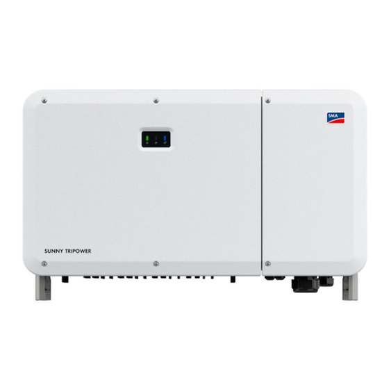
Page 18: Product Overview
5 Product Overview SMA Solar Technology AG Product Overview Product Description Figure 1: Design of the product Position Designation LEDs The LEDs indicate the operating state of the product. Type label The type label clearly identifies the product. The type label must remain permanently attached to the product. - Page 19 SMA Solar Technology AG 5 Product Overview Icon Explanation Beware of hot surface The product can get hot during operation. Danger to life due to high voltages in the inverter; observe a waiting time of 5 5 min minutes. High voltages that can cause lethal electric shocks are present in the live com- ponents of the inverter.
-
Page 20: Interfaces And Functions
The product is equipped with a Modbus interface. The inverter is delivered with the Modbus interface activated as standard. The Modbus interface of the supported SMA products is designed for industrial use – via SCADA systems, for example – and has the following tasks: •... -
Page 21: Led Signals
Connected, it is necessary that the product is permanently connected to Sunny Portal and the data of the operator and qualified person is stored in Sunny Portal and up-to-date. SMA Smart Connected can exclusively be used if the inverter is used in conjunction with an SMA Data Manager M. -
Page 22: System Overview
5 Product Overview SMA Solar Technology AG System Overview SUNNY TRIPOWER PV STRINGS RIPPLE CONTROL CORE2 RECEIVER GRID OPERATOR SUNNY PORTAL powered by ennexOS DATA MANAGER INTERNET 3rd PARTY DIRECT SCADA SYSTEM MARKETER GRID ANALYZER TRANSFORMER UTILITY STATION GRID Ethernet... -
Page 23: Mounting
Installing Optional AC Sealing Plate An optional AC sealing plate with 4 cable glands can be used for the product. The optional AC sealing plate can be ordered in the SMA online shop (www.sma-onlineshop.com) by indicating the material number 201013-00.01. -
Page 24: Mounting To Profile Rails
6 Mounting SMA Solar Technology AG ☐ A solid support surface must be available (e.g. concrete or masonry, free-standing constructions). ☐ The mounting location must not be exposed to direct solar irradiation. If the product is exposed to direct solar irradiation, the exterior plastic parts might age prematurely and overheating might occur. -
Page 25: Mounting The Product To Profile Rails
SMA Solar Technology AG 6 Mounting Requirements for the profile rails: ☐ The profile rails must be designed for the load and orientation of the inverters in the PV system. The profile rails might need to be reinforced. ☐ The spacing of the profile rails must be designed for the spacing of the holes in the bracket parts for the mounting bracket. - Page 26 6 Mounting SMA Solar Technology AG Procedure: 1. Screw the bracket parts to the ends of the connecting rod (PH2, torque: 1.5 Nm) using the cheese head screws (M4x10) to mount the mounting bracket. 2x 2x 2x 2. Align the mounting bracket using a spirit level and mark the drilling positions on the profile rails.
- Page 27 SMA Solar Technology AG 6 Mounting 6. If the inverter is to be hooked into the mounting bracket using a hoist, screw the eye bolts into the 2 upper tapped holes on the right-hand and left-hand side of the inverter and attach the hoist to them. The hoist must be suitable to take the weight of the inverter.
-
Page 28: Mounting The Product On A Wall
6 Mounting SMA Solar Technology AG 10. Use the pan head screws (M5x65) to attach the inverter to the mounting bracket (PH3, torque: 4.5 Nm). 2x 2x Mounting the Product on a Wall CAUTION Risk of injury due to weight of product Injuries may result if the product is lifted incorrectly or dropped while being transported or mounted. - Page 29 SMA Solar Technology AG 6 Mounting 3. Drill the bore holes (Ø 12 mm) at the marked areas. 4. Attach the mounting bracket to the wall using the heavy-duty anchors. 5. Remove the sealing screws on the sides of the inverter using a flat-blade screwdriver (4 mm).
- Page 30 6 Mounting SMA Solar Technology AG 8. Hook the inverter into the mounting bracket. 9. Remove all 4 transport handles from the tapped holes or remove the eye bolts of the hoist and and once again screw in the sealing screws (flat-blade screwdriver 4 mm, torque: 2 Nm).
-
Page 31: Opening The Cable Compartment
SMA Solar Technology AG 7 Opening the Cable Compartment Opening the Cable Compartment For some of the actions described in this document, the cable compartment must be opened. Procedure: DANGER Danger to life due to electric shock • Disconnect the inverter from all voltage sources (see Section 11, page 55). -
Page 32: Electrical Connection
8 Electrical Connection SMA Solar Technology AG Electrical Connection Overview of the Connection Area 8.1.1 View from Below COM 1 COM 2 DC SWITCH 1 DC SWITCH 3 COM 3 COM 4 DC SWITCH 2 DC SWITCH 4 Figure 6: Enclosure openings at the bottom of the inverter... -
Page 33: Ac Connection
1100 mA or higher (see Technical Information "Criteria for Selecting a Residual-Current Device" in www.SMA-Solar.com for information on how to select a residual-current device). Each inverter in the system must be connected to the utility grid via a separate residual-current device. -
Page 34: Connecting The Inverter To The Utility Grid
In case of installations with long outdoor cabling routes, additional measures to reduce overvoltage category IV to overvoltage category III are required (see the Technical Information "Overvoltage Protection" at www.SMA-Solar.com). 8.2.2 Connecting the Inverter to the Utility Grid Requirements: ☐... - Page 35 SMA Solar Technology AG 8 Electrical Connection 6. For conductors made of aluminum, remove the oxide film and apply protective grease to the conductors. 7. Loosen the 4 screws of the protective cover in front of the AC connection (PH2) and remove the protective cover.
- Page 36 8 Electrical Connection SMA Solar Technology AG 11. Insert the stripped conductor section into the ring terminal lugs and crimp using a crimping tool. 12. Pull the heat-shrink tubings onto the crimped section 4x 4x of the ring terminal lugs and using a hot-air blower shrink them so that they are in firm contact with the ring terminal lugs.
-
Page 37: Connecting The Grounding
SMA Solar Technology AG 8 Electrical Connection 18. Tighten the 2 screws on the cable compartment cover (TX30, torque: 4.3 Nm). 2x 2x 8.2.3 Connecting the Grounding An additional grounding of the inverter is required to protect from touch current in case the grounding conductor fails at the terminal of the AC cable. -
Page 38: Connecting The Network Cables
8 Electrical Connection SMA Solar Technology AG 3. Insert the stripped section of the grounding cable into the ring terminal lug and crimp using a crimping tool. 4. Pull the heat-shrink tubing onto the crimped section of the ring terminal lug and using a hot-air blower shrink them so that they are in firm contact with the ring terminal lugs. - Page 39 SMA Solar Technology AG 8 Electrical Connection Network cable requirements: The cable length and quality affect the quality of the signal. Observe the following cable requirements: ☐ Cable type: 100BaseTx ☐ Cable category: minimum CAT5e ☐ Plug type: RJ45 of Cat5, Cat5e or higher ☐...
-
Page 40: Dc Connection
8 Electrical Connection SMA Solar Technology AG 8. Put the RJ45 plug of the cable into one of the network jacks of the communication assembly. 9. Ensure that the network cable does not form any loops in the device and is no longer than necessary. - Page 41 SMA Solar Technology AG 8 Electrical Connection NOTICE Destruction of the inverter due to overvoltage If the open-circuit voltage of the PV modules exceeds the maximum input voltage of the inverter, the inverter can be destroyed due to overvoltage. • If the open-circuit voltage of the PV modules exceeds the maximum input voltage of the inverter, do not connect any strings to the inverter and check the design of the PV system.
-
Page 42: Connecting The Pv Array
8 Electrical Connection SMA Solar Technology AG ☑ The stranded wire can be seen inside the clamping bracket chamber. 4. If the stranded wire is not visible in the chamber, the cable is not correctly inserted and the connector must be reassembled. To do this, the cable must be removed from the connector. - Page 43 SMA Solar Technology AG 8 Electrical Connection WARNING Danger to life due to electric shock from destruction of the measuring device due to overvoltage Overvoltage can damage a measuring device and result in voltage being present in the enclosure of the measuring device. Touching the live enclosure of the measuring device results in death or lethal injuries due to electric shock.
- Page 44 8 Electrical Connection SMA Solar Technology AG 4. Check whether the DC connectors have the correct polarity. If the DC connector is equipped with a DC cable of the wrong polarity, the DC connector must be reassembled. The DC cable must always have the same polarity as the DC connector.
-
Page 45: Disassembling The Dc Connectors
SMA Solar Technology AG 8 Electrical Connection 11. Insert the DC connectors with sealing plugs into the corresponding DC inputs on the inverter. click click ☑ The DC connectors snap into place. 12. Ensure that the DC connectors with sealing plugs are securely in place. - Page 46 8 Electrical Connection SMA Solar Technology AG 3. Unlock the DC connector. To do this, insert a flat- blade screwdriver (blade width: 3.5 mm) into the side catch mechanism and pry the catch mechanism open. 4. Carefully pull the DC connector apart.
-
Page 47: Commissioning
Commissioning an inverter that is captured in a communication device When the inverter is captured in a communication device, the communication device (e.g. SMA Data Manager) is the unit for configuring the total system. The configuration is transferred to all inverters in the system. - Page 48 9 Commissioning SMA Solar Technology AG Procedure: 1. Close the cable compartment and tighten the screws on the cable compartment cover (TX 30, torque: 4.3 Nm). 2x 2x 2. Switch on all 4 DC load-break switches. 4x 4x 3. Switch on the AC circuit breaker.
-
Page 49: Operation
• Generally applicable access address: IP address manually assigned or assigned by the DHCP server (router) (identification via network scanner software or network configuration of the router). • Access address for Apple, Android, Windows and Linux systems: SMA[serial number].local (e.g. SMAA2102031234.local) Requirements: ☐... -
Page 50: Logging In And Out Of The User Interface
10 Operation SMA Solar Technology AG Procedure: • Open the web browser of your smart device. Enter the IP address of the product in the address bar of the web browser. ☑ The login page of the user interface opens. -
Page 51: Start Page Design Of The User Interface
SMA Solar Technology AG 10 Operation 10.3 Start Page Design of the User Interface Figure 9: Design of the user interface's home page (example) Position Designation Menu • Overview – General information Displays current measured values, the communication status and the device information •... -
Page 52: Changing The Password
10 Operation SMA Solar Technology AG Position Designation Language selection • Setting the language of the user interface User settings • Change password • Logout Status display The various areas display information on the current status of the inverter. • Yield Displays the energy yield of the inverter •... -
Page 53: Configuring The Country Data Set
"Modbus® parameters and measured values" at www.SMA-Solar.com. Communication via Modbus is the condition for the operation of the inverter with the SMA Data Manager M. The Data Manager M enables monitoring and controlling of the inverter in Sunny Portal. For this, the inverter must be registered via Sunspec Modbus in the Data Manager M (see operating manual of the Data Manager M). - Page 54 10 Operation SMA Solar Technology AG Measures for data security during activated Modbus interface If you activate the Modbus interface, there is a risk that unauthorized users may access and manipulate the data or devices in your PV system. To ensure data security, take appropriate protective measures such as: •...
-
Page 55: Disconnecting The Inverter From Voltage Sources
SMA Solar Technology AG 11 Disconnecting the Inverter from Voltage Sources 11 Disconnecting the Inverter from Voltage Sources Prior to performing any work on the product, always disconnect it from all voltage sources as described in this section. Always adhere to the prescribed sequence. - Page 56 11 Disconnecting the Inverter from Voltage Sources SMA Solar Technology AG DANGER Danger to life due to electric shock when touching exposed DC conductors or DC plug contacts if the DC connectors are damaged or loose The DC connectors can break or become damaged, become free of the DC cables, or no longer be connected correctly if the DC connectors are released and disconnected incorrectly.
- Page 57 SMA Solar Technology AG 11 Disconnecting the Inverter from Voltage Sources 11. Verify a de-energized state of the AC connection between L1 and L2, L2 and L3, L1 and L3 und L1 and grounding conductor, L2 and grounding conductor and L3 and grounding conductor using a 0 .
-
Page 58: Event Messages
12 Event messages SMA Solar Technology AG 12 Event messages Event messages can be found under the parameter group Extended RO. The basic procedure for viewing and changing operating parameters is explained in another section (see Section 10.5, page 52). Event number... - Page 59 SMA Solar Technology AG 12 Event messages Event number Message, cause and corrective measures Grid undervoltage The grid voltage is lower than the set conservation value. Corrective measures: • Wait until the grid voltage is within the normal range again. In general, the inverter is reconnected to the supply grid when the grid voltage is back within the normal range.
- Page 60 12 Event messages SMA Solar Technology AG Event number Message, cause and corrective measures Grid overfrequency The grid frequency exceeds the permissible upper limit of the inverter. Corrective measures: • Wait until the grid frequency is within the normal range again. In general, the inverter is reconnected to the supply grid when the grid frequency is back within the normal range.
- Page 61 SMA Solar Technology AG 12 Event messages Event number Message, cause and corrective measures Device fault There is a disturbance in the device. Corrective measures: • Wait until the inverter is in normal mode again. • Switch off the AC load-break switches and the DC load-break switches and switch them on again after 15 minutes to restart the inverter.
- Page 62 12 Event messages SMA Solar Technology AG Event number Message, cause and corrective measures Grid overvoltage The grid voltage is higher than the set conservation value. Corrective measures: • Wait until the grid voltage is within the normal range again.
- Page 63 SMA Solar Technology AG 12 Event messages Event number Message, cause and corrective measures Device fault Corrective measures: • Wait until the inverter is in normal mode again. • Switch off the AC load-break switches and the DC load-break switches and switch them on again after 15 minutes to restart the inverter.
- Page 64 12 Event messages SMA Solar Technology AG Event number Message, cause and corrective measures Low system insulation resistance Generally, the fault is caused by poor insulation of the module/cable to ground or by rainfall and a moist environment. Corrective measures: •...
- Page 65 SMA Solar Technology AG 12 Event messages Event number Message, cause and corrective measures Device fault Corrective measures: • Wait until the inverter is in normal mode again. • Switch off the AC load-break switches and the DC load-break switches and switch them on again after 15 minutes to restart the inverter.
- Page 66 12 Event messages SMA Solar Technology AG Event number Message, cause and corrective measures Error during self-test for protective status on the grid side Corrective measures: • Restart the processor or rectify the error via the user interface. • If the fault cannot be rectified using the indicated corrective measures, contact Service.
- Page 67 SMA Solar Technology AG 12 Event messages Event number Message, cause and corrective measures String [#] reverse polarity Corrective measures: • Check whether there is reverse polarity on the corresponding PV string. If so, open the DC switch and adjust the polarity if the solar irradiation is low and the string electrical current is below 0.5 A.
- Page 68 12 Event messages SMA Solar Technology AG Event number Message, cause and corrective measures String [#] reverse polarity alarm Corrective measures: • Check whether there is reverse polarity on the corresponding PV string. If so, open the DC switch and adjust the polarity if the solar irradiation is low and the string electrical current is below 0.5 A.
- Page 69 SMA Solar Technology AG 12 Event messages Event number Message, cause and corrective measures String [#] reverse polarity alarm Corrective measures: • Check whether there is reverse polarity on the corresponding PV string. If so, open the DC switch and adjust the polarity if the solar irradiation is low and the string electrical current is below 0.5 A.
-
Page 70: Decommissioning The Inverter
13 Decommissioning the Inverter SMA Solar Technology AG 13 Decommissioning the Inverter To decommission the inverter completely upon completion of its service life, proceed as described in this Section. Requirements: ☐ Original packaging or packaging suitable for the weight and dimensions of the product must be available. - Page 71 SMA Solar Technology AG 13 Decommissioning the Inverter 11. Remove the RJ45 plug of the cable from the network jack of the communication assembly. 12. Remove the swivel nut from the cable gland for the communication cable. 13. Feed the network cable out of the device through the cable gland for communication cables.
- Page 72 13 Decommissioning the Inverter SMA Solar Technology AG 21. If the inverter is to be lifted out of the mounting bracket without using a hoist, screw the transport handles as far as they will go into the tapped holes on the right-hand and left-hand side until they lie flush with the enclosure.
-
Page 73: Procedure For Receiving A Replacement Device
6. If the defective product had been registered by a communication product, replace it with the new product in the communication product (see operating manual of communication product). 7. Pack the defective product in the packaging of the replacement device and arrange with SMA Solar Technology AG for it to be picked up. -
Page 74: Maintenance
NOTICE Damage to the inverter due to unapproved spare parts If accessories and spare parts not approved by SMA Solar Technology AG are used for maintenance, the product may be damaged. • Only use spare parts approved by SMA Solar Technology AG. -
Page 75: Clean The Product
SMA Solar Technology AG 15 Maintenance Task Description Time period Check the cable inputs Check whether all cable glands are sufficiently Every 12 months sealed. Seal the cable glands again if neces- sary. Check the electrical Check that all cables are properly connected Every 6 to 12 months... -
Page 76: Installing The Fan Assembly
15 Maintenance SMA Solar Technology AG 3. Loosen the screw on the fan holder (PH2). 4. Pull out the fan holder. 5. Clean the fan assembly with a soft brush or a vacuum cleaner. If the fan assembly is defective, replace it. -
Page 77: Technical Data
SMA Solar Technology AG 16 Technical Data 16 Technical Data DC Input Maximum PV array power 165000 Wp STC Maximum input voltage 1100 V MPP Voltage Range 200 V to 1000 V MPP Voltage Range for rated power 500 V to 800 V Rated input voltage 585 V... - Page 78 16 Technical Data SMA Solar Technology AG Duration of the maximum residual output current 1 ms Total harmonic distortion < 3 % Inrush current < 10% of the nominal AC current for a maximum of 10 ms Rated grid frequency 50 Hz Grid frequency 50 Hz / 60 Hz Operating range at grid frequency 50 Hz...
- Page 79 SMA Solar Technology AG 16 Technical Data Length x width x height of the packaging 1220 mm x 840 mm x 618 mm Transport weight 125 kg Climatic category in accordance with IEC 4K4H 60721‑3‑4 Environmental category Outdoors Pollution degree of all enclosure parts Operating temperature range -30°C to +60°C...
- Page 80 16 Technical Data SMA Solar Technology AG Equipment DC terminal SUNCLIX DC connector AC connection Cable lugs (up to 240 mm²) Torques Connecting rod screws for mounting bracket 1.5 Nm (M4x10, PH2) Screws to mount the mounting bracket to profile...
-
Page 81: Contact
SMA Solar Technology AG 17 Contact 17 Contact You can find your country's contact information at: https://go.sma.de/service Operating manual STP110-60-BE-en-13... - Page 82 (L 174/88, June 8, 2011) and 2015/863/EU (L 137/10, March 31, 2015) (RoHS) SMA Solar Technology AG confirms herewith that the products described in this document are in compliance with the fundamental requirements and other relevant provisions of the above- mentioned directives. The entire EU Declaration of Conformity can be found at www.SMA- Solar.com.
- Page 83 • The Restriction of the Use of Certain Hazardous Substances in Electrical and Electronic Equipment Regulations 2012 SMA Solar Technology AG confirms herewith that the products described in this document are in compliance with the fundamental requirements and other relevant provisions of the above- mentioned regulations.
- Page 84 www.SMA-Solar.com...
Need help?
Do you have a question about the SUNNY TRIPOWER CORE2 and is the answer not in the manual?
Questions and answers